Downloaded 17 times
![REFERENCES
[1] N. Milivojevic, M. Krishnamurthy, Y. Gurkaynak, A. Sathyan, Y.-J. Lee, and A. Emadi, “Stability analysis of FPGA-based
control of brushless dc motors and generators using digital PWM technique,” IEEE Trans. Ind. Electron., vol. 59, no. 1, pp. 343–351,
Jan. 2012.
[2] X. Huang, A. Goodman, C. Gerada, Y. Fang, and Q. Lu, “A single sided matrix converter drive fora brushless dc motor in
aerospace applications,” IEEE Trans. Ind. Electron., vol. 59, no. 9, pp. 3542–3552, Sep. 2012.
[3] X. Huang, A. Goodman, C. Gerada, Y. Fang, and Q. Lu, “Design of a five-phase brushless dc motor for a safety critical aerospace
application,” IEEE Trans. Ind. Electron., vol. 59, no. 9, pp. 3532–3541, Sep. 2012.
[4] J.-G. Lee, C.-S. Park, J.-J. Lee, G. H. Lee, H.-I. Cho, and J.-P. Hong, “Characteristic analysis of brushless motor considering drive
type,” in Proc. Korean Inst. Electr. Eng., Jul. 2002, pp. 589–591.
[5] T. H. Kim and M. Ehsani, “Sensor less control of BLDC motors from near-zero to high speeds,” IEEE Trans. Power Electron., vol.
19, no. 6, pp. 1635–1645, Nov. 2004.
[6] T. J. E. Miller, Switched Reluctance Motor and Their Control. London, U.K.: Clarendon, 1993.
[7] K. Ilhwan, N. Nobuaki, K. Sungsoo, P. Chanwon, and Chansu Yu, “Compensation of torque ripple in high performance BLDC
motor drives,” Control Eng. Pract., vol. 18, pp. 1166–1172, Oct. 2010.
[8] S. S. Bharatkar, R. Yanamshetti, D. Chatterjee, and A. K. Ganguli, “Reduction of commutation torque ripple in a brushless dc
motor drive,” in Proc. 2008 IEEE 2nd Int. Power Energy Conf., 2008, pp. 289–294.
[9] K.-Y. Nam, W.-T.L ee, C.-M.Lee, and J.-P.Hong,“Reducing torque ripple of brushless dc motor by varying input voltage,” IEEE
Trans. Magn., vol. 42, no. 4, pp. 1307–1310, Apr. 2006.
[10] J. H. Song and I. Choy, “Commutation torque reduction in brushless dc motor drives using a single dc current sensor,” IEEE
Trans. Power Electron., vol. 19, no. 2, pp. 312–319, Mar. 2004.
[11] X. F. Zhang and Z. Y. Lu, “A new BLDC motor drives method based on BUCK converter for torque ripple reduction, ”Proc. IEEE
Power Electron. Motion Control Conf., 2006, pp. 1–4.
[12] W. Chen, C. Xia, and M. Xue, “A torque ripple suppression circuit for brushless dc motors based on power dc/dc converters,” in
Proc. IEEE Ind. Electron. Appl. Conf., 2008, pp. 1453–1457.
[13] T.Shi,Y.Guo,P.Song,andC.Xia,“Anewapproachofminimizingcommutation torque ripple for brushless dc motor based on dc–dc
converter,” IEEE Trans. Ind. Electron., vol. 57, no. 10, pp. 3483–3490, Oct. 2010.
[14] V. Viswanathan and S. Jeevananthan, “Approach for torque ripple reduction for brushless dc motor based on three-level neutral-
point-clamped inverter with dc-dc converter,” IET Power Electron., vol. 8, no. 1, pp. 47– 55, 2014.
[15] T. Sheng, X. Wang, J. Zhang, and Z. Deng, “Torque-ripple mitigation for brushless dc machine drive system using one-cycle
average torque control,”IEEETrans.Ind.Electron.,vol.62,no.4,pp.2114–2122,Apr.2015.
[16] C.Xia, Y. Xiao ,W.Chen, and T.Shi, “Torque ripple reduction in brushless dc drives based on reference current optimization using
integral variable structurecontrol,”IEEETrans.Ind.Electron.,vol.61,no.2,pp.738–752, Feb. 2014.](https://image.slidesharecdn.com/commutationtorquerippleinbldcbysepicandnpc-191108044144/75/Commutation-torque-ripple-in-bldc-by-sepic-and-npc-24-2048.jpg)


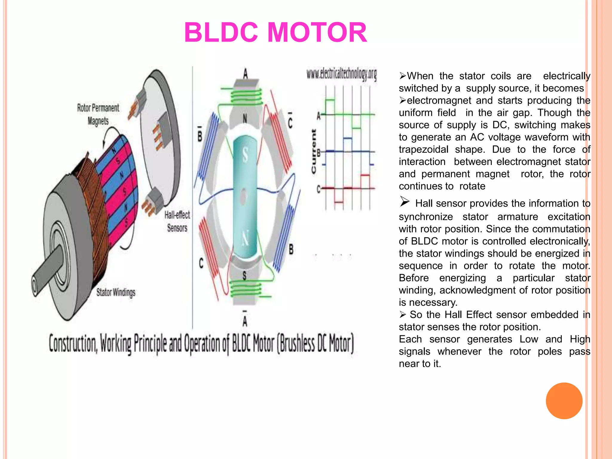
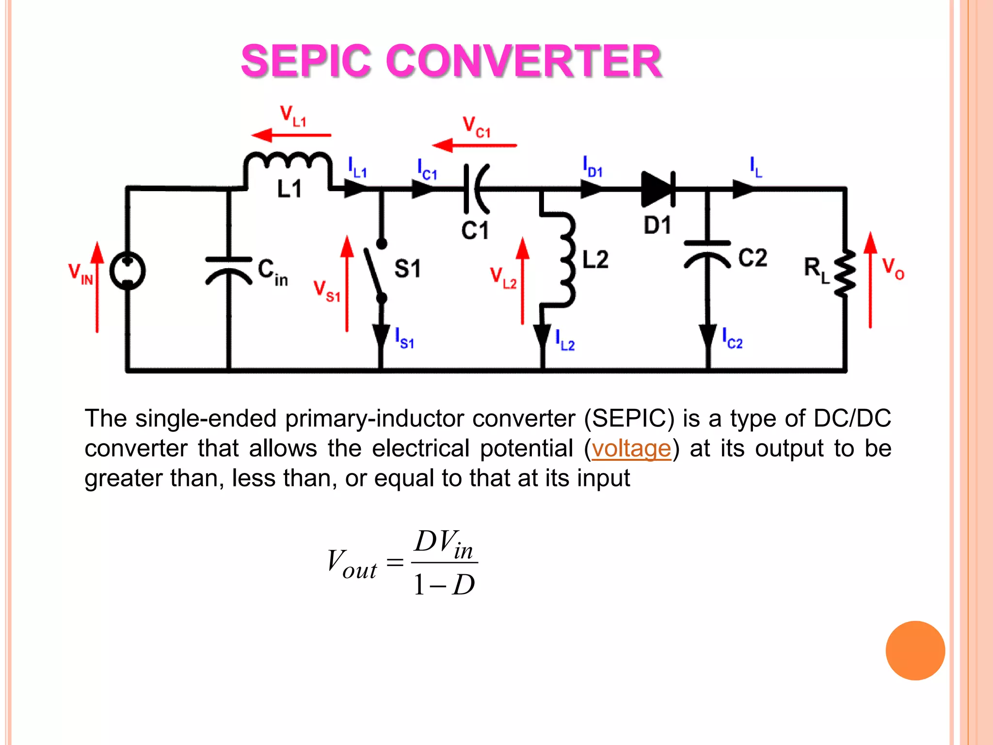
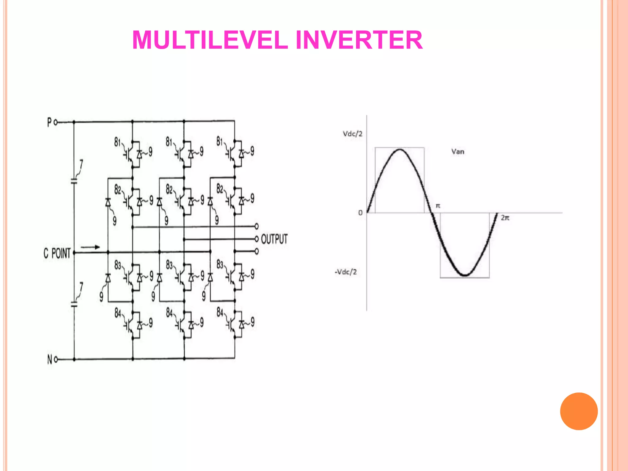
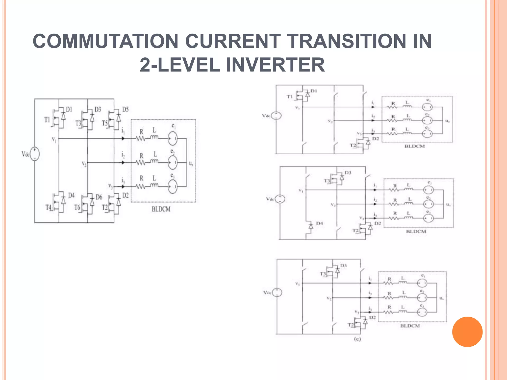
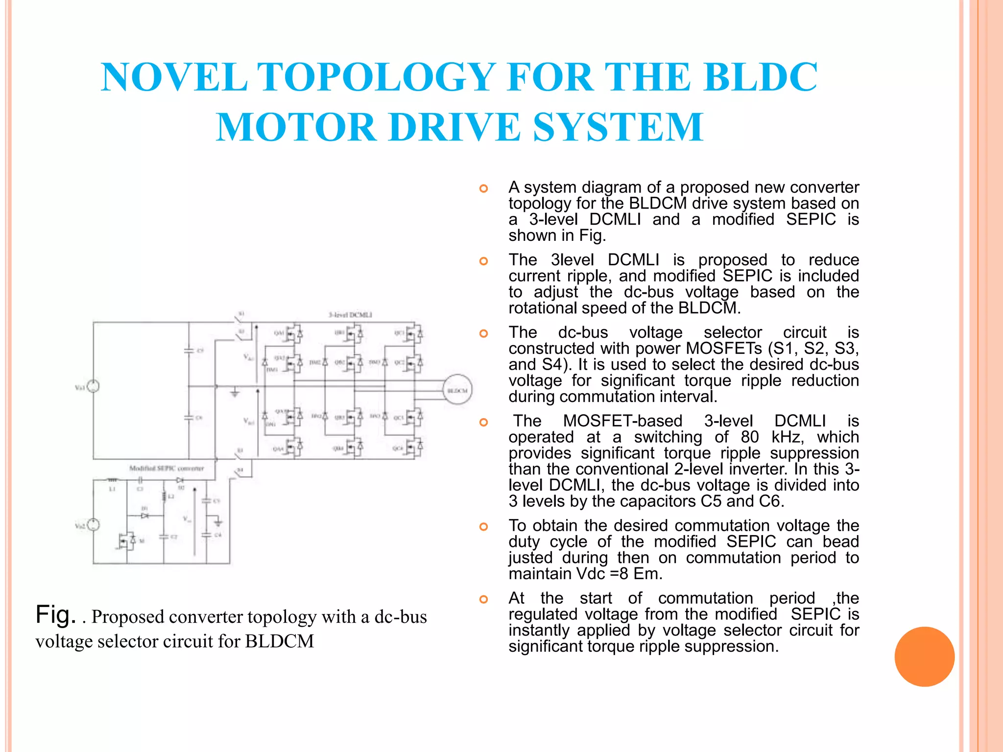
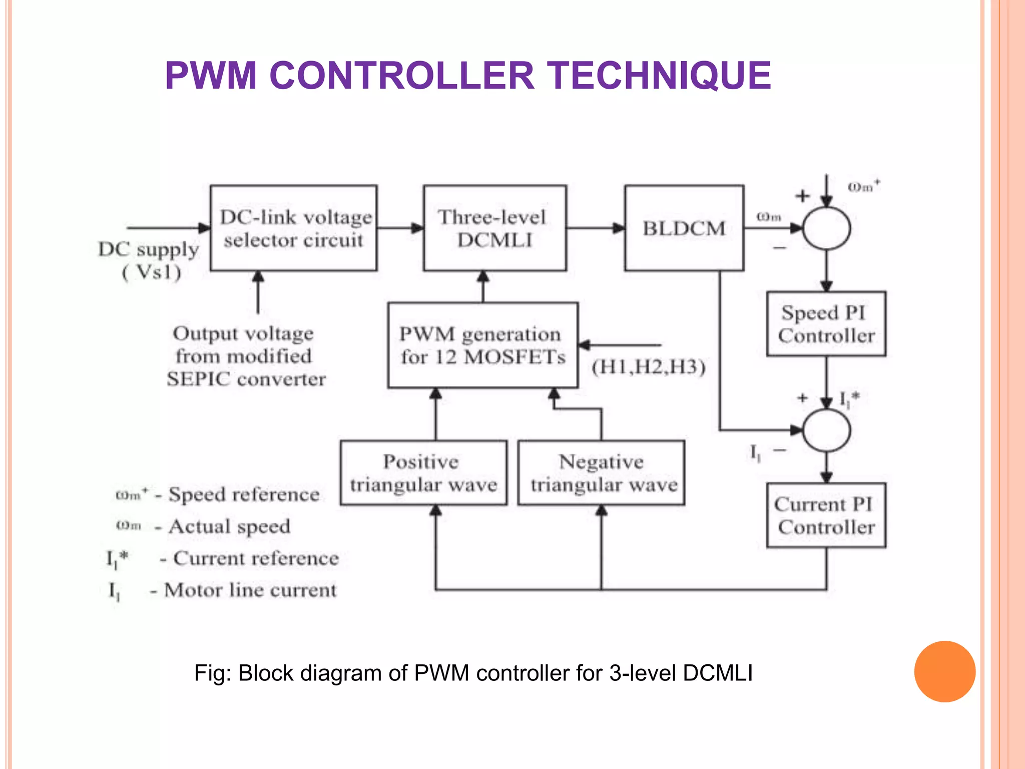
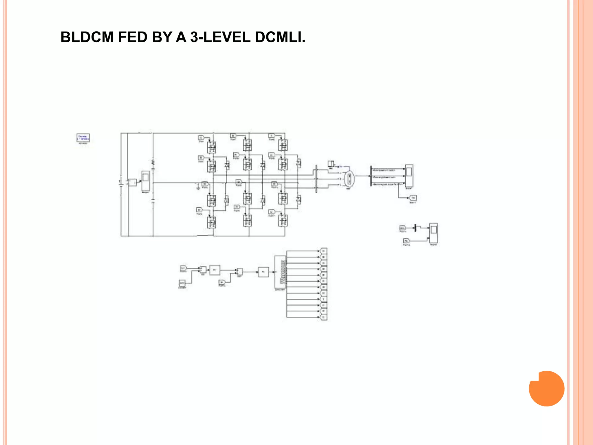
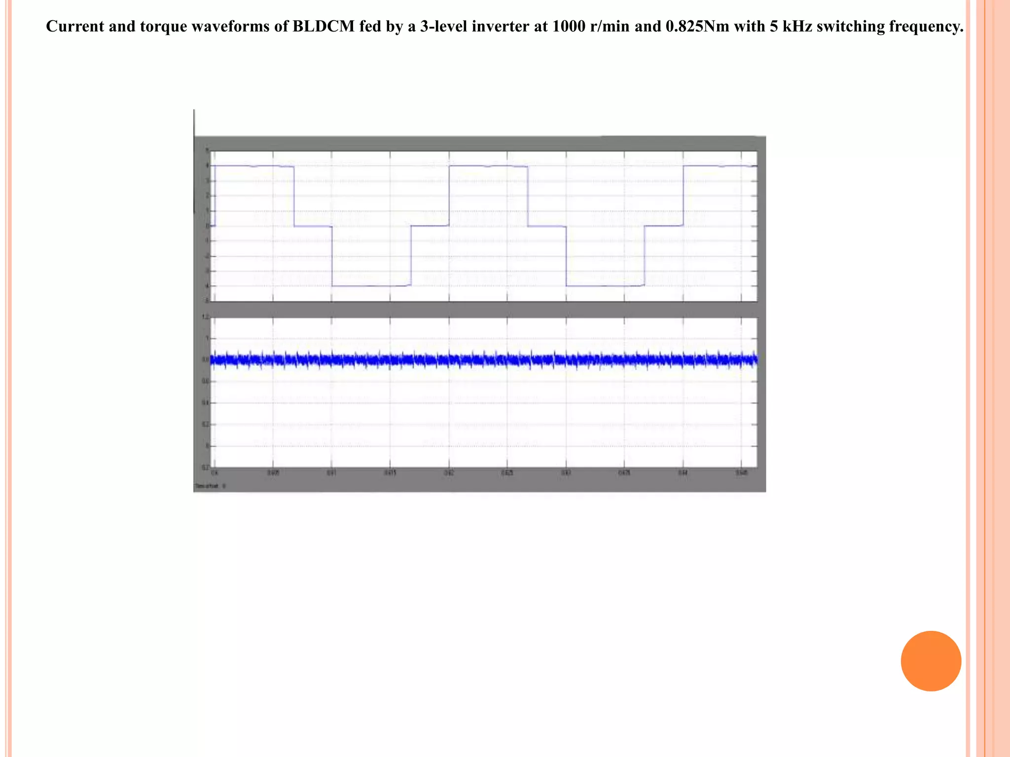
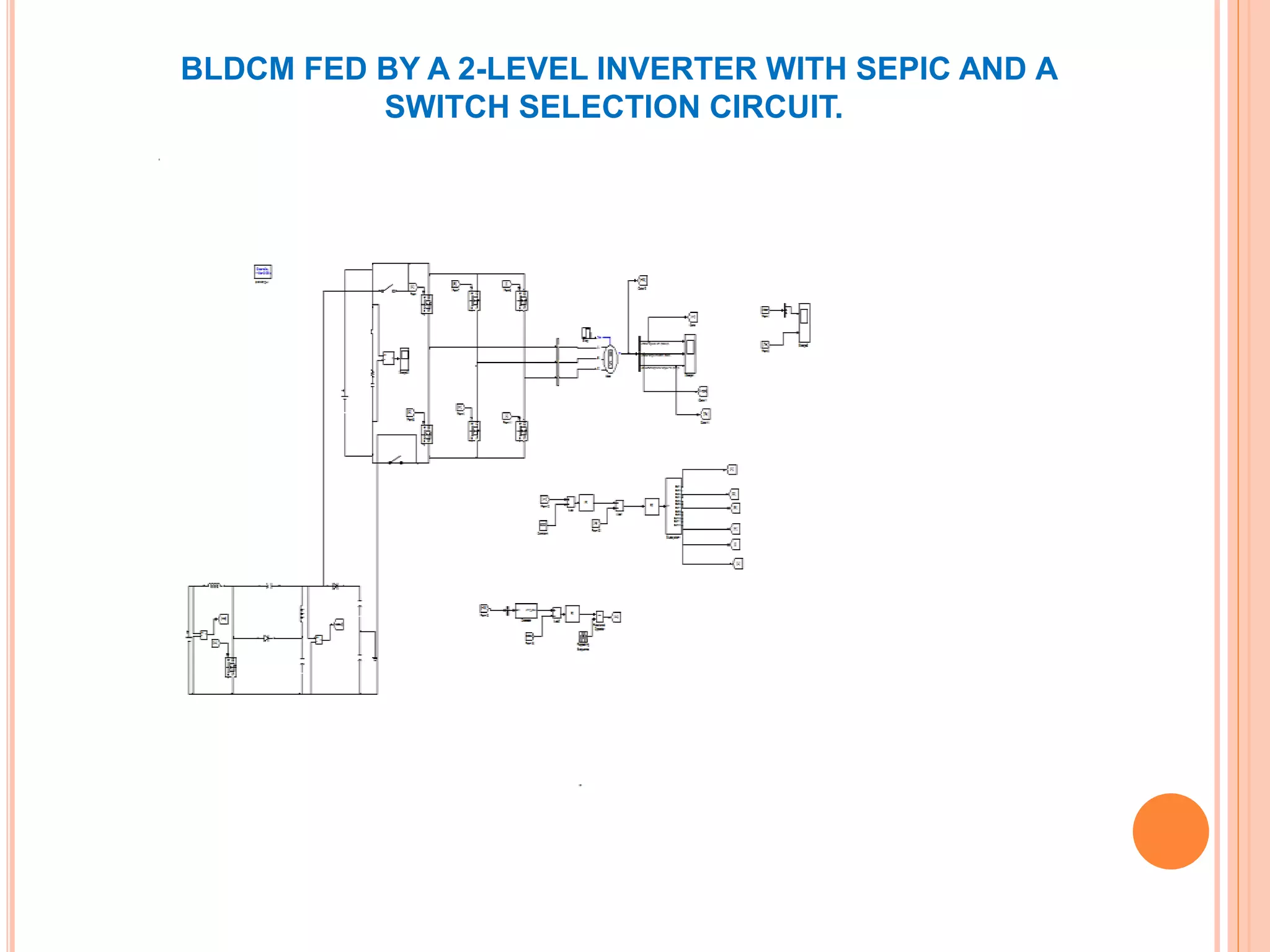
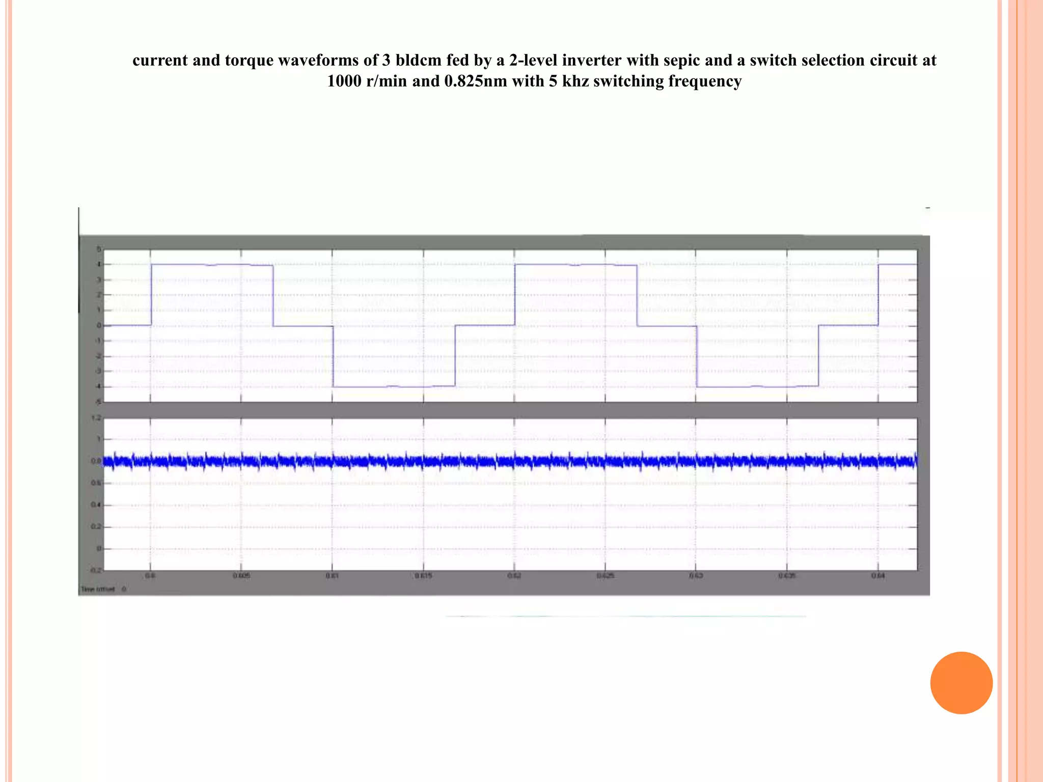
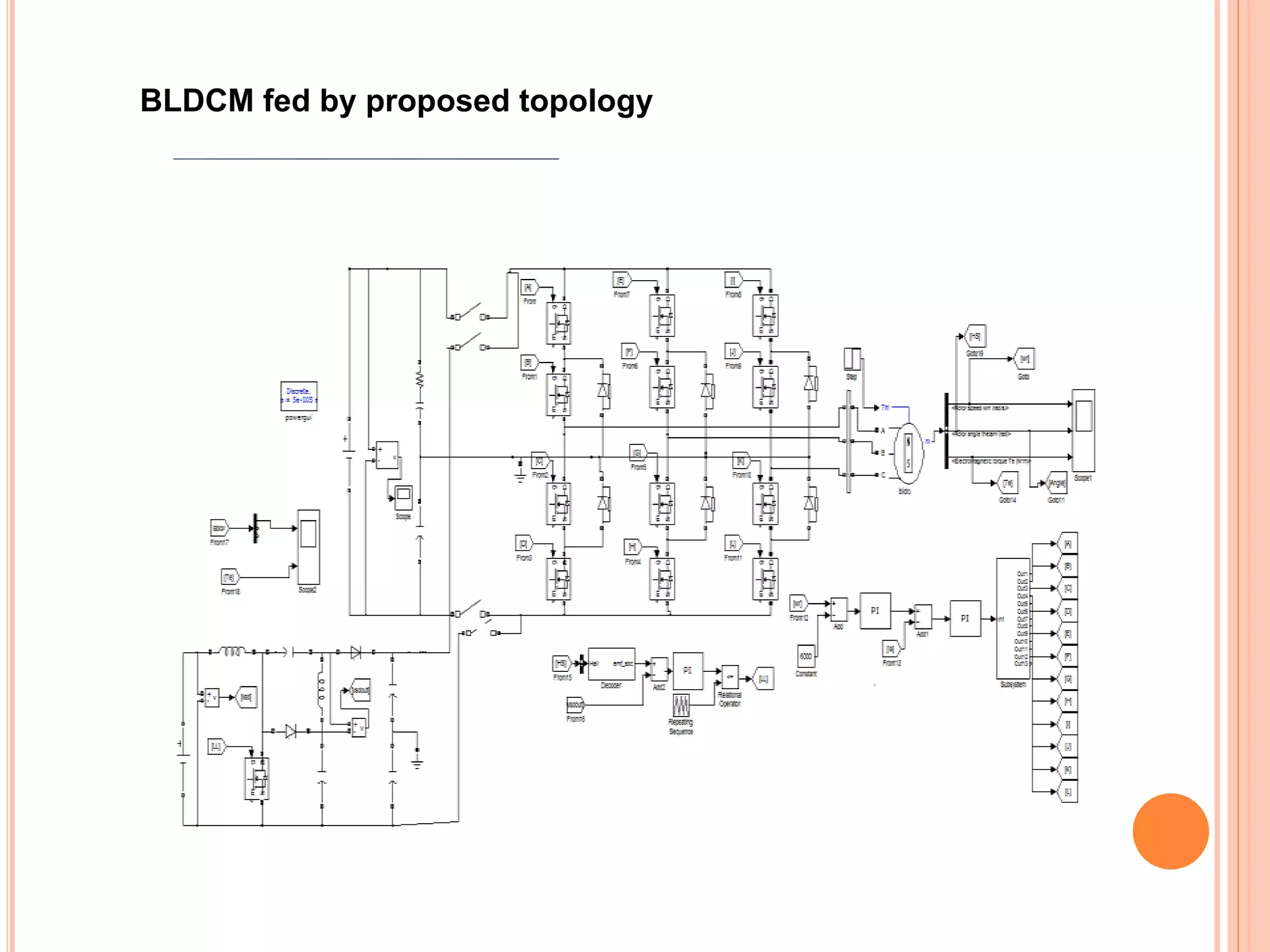
This paper proposes a novel power converter topology combining a modified SEPIC and a three-level diode clamped multilevel inverter (3-level DCMli) to effectively reduce commutation torque ripple in brushless DC motor (BLDCM) drive systems. The system utilizes a DC-bus voltage selector circuit for optimized voltage application during commutation intervals, demonstrating significant torque ripple suppression in both simulation and experimental results. The proposed topology offers enhanced performance, making it suitable for high-speed and low-speed applications in various industries.


![[IJET V2I5P12] Authors: Mr. Harikrishnan U, Dr. Bos Mathew Jos, Mr.Thomas P R...](https://cdn.slidesharecdn.com/ss_thumbnails/ijet-v2i5p12-161107141950-thumbnail.jpg?width=640&height=640&fit=bounds)


![[IJET V2I5P10] Authors: Vinith Das, Dr. Babu Paul, Prof. Elizabeth Seba stian](https://cdn.slidesharecdn.com/ss_thumbnails/ijet-v2i5p10-161107141332-thumbnail.jpg?width=640&height=640&fit=bounds)


