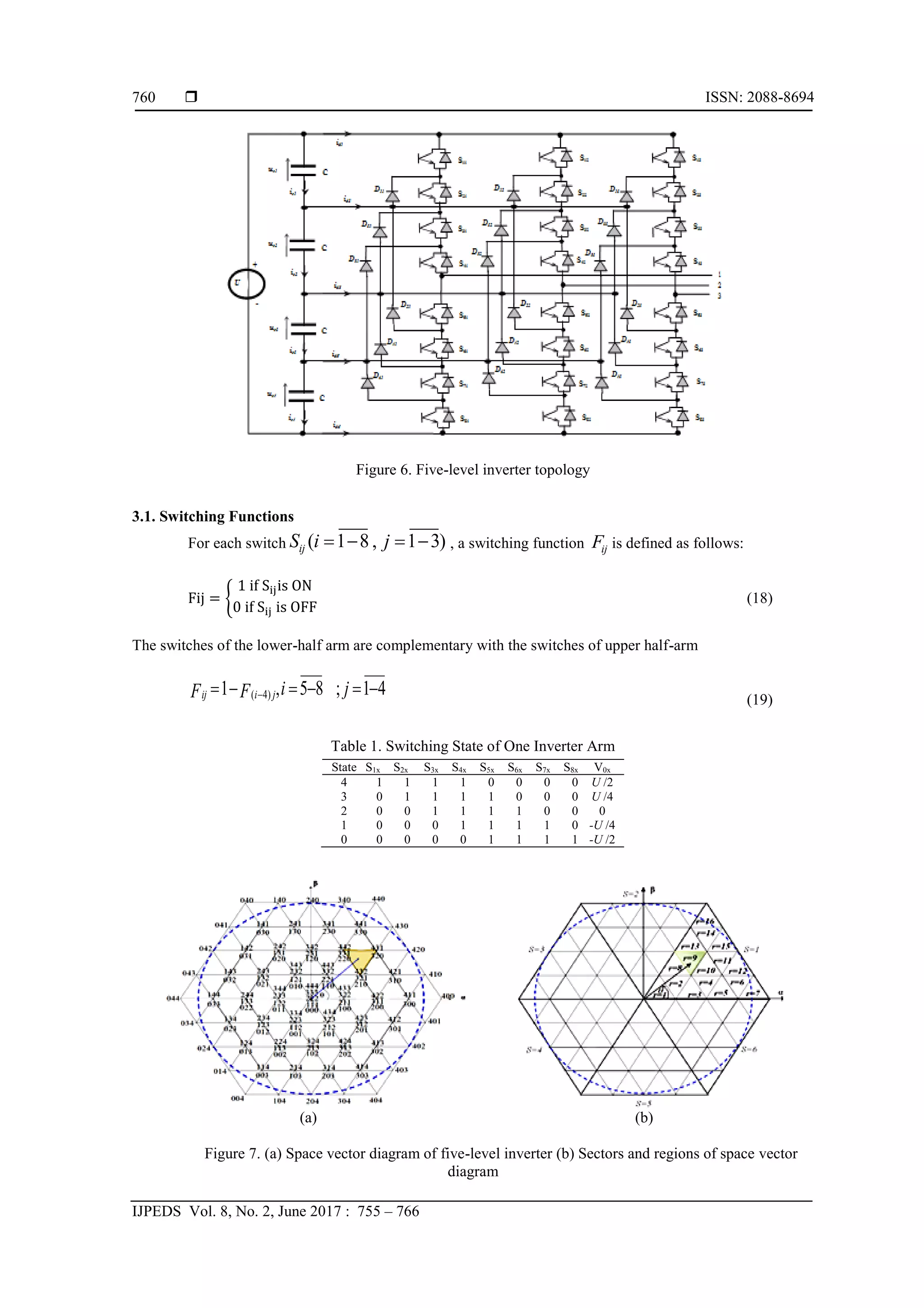
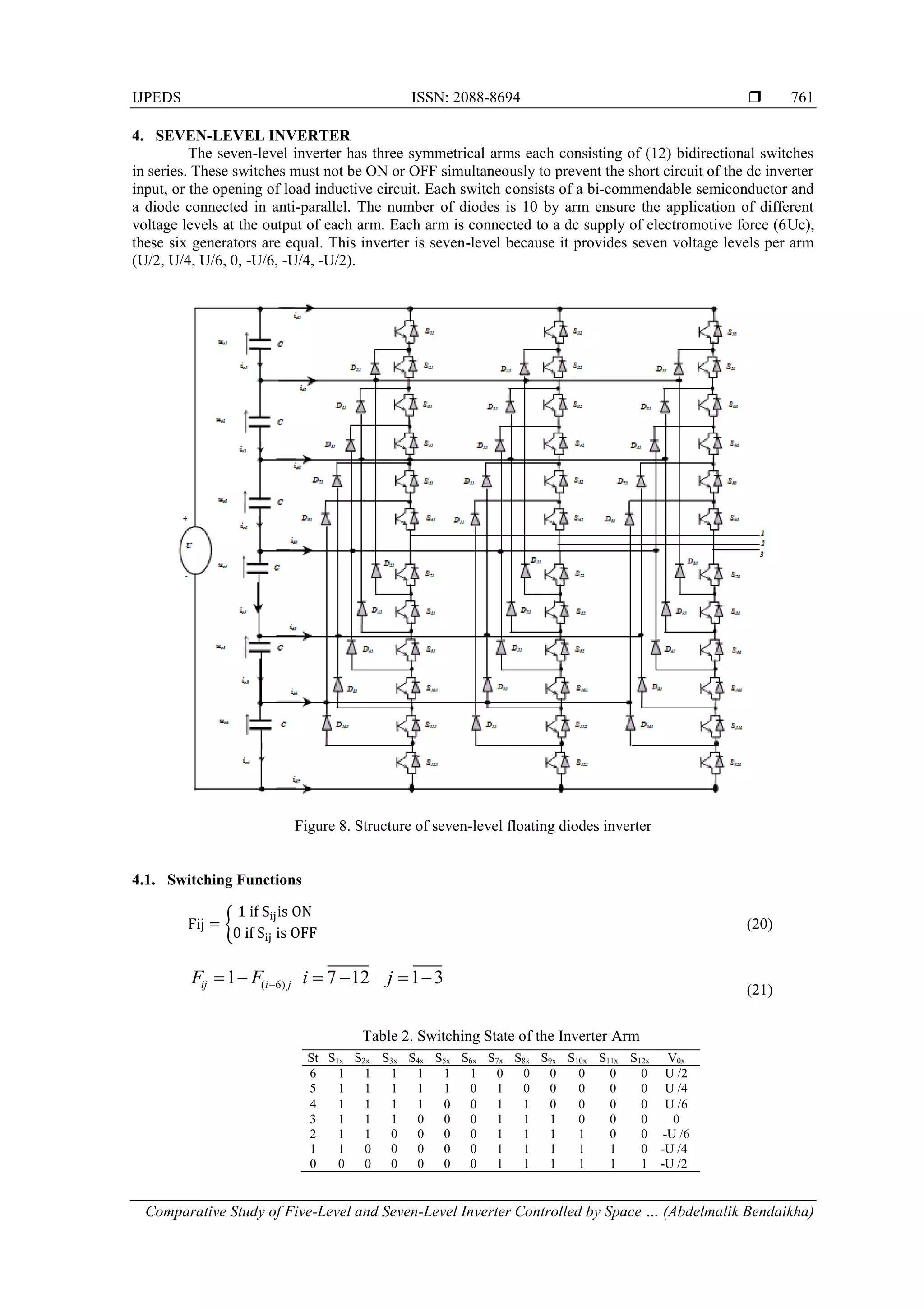
This document presents a comparative study of five-level and seven-level diode-clamped inverters controlled by space vector pulse width modulation (SVPWM). MATLAB/SIMULINK models of the two inverter topologies were developed. SVPWM control algorithms based on symmetrical sequence were used for each inverter. Both inverters were simulated driving an induction motor. The results showed that the seven-level inverter produced less harmonic distortion and torque fluctuations in the motor, while the five-level inverter had lower commutation losses. The seven-level inverter provided better motor dynamic response.
![International Journal of Power Electronics and Drive System (IJPEDS)
Vol. 8, No. 2, June 2017, pp. 755~766
ISSN: 2088-8694, DOI: 10.11591/ijpeds.v8i2.pp755-766 755
Journal homepage: http://iaesjournal.com/online/index.php/IJPEDS
Comparative Study of Five-Level and Seven-Level Inverter
Controlled by Space Vector Pulse Width Modulation
Abdelmalik Bendaikha1
, Salah Saad2
1
Department of Electrical Engineering, Faculty of Technology, University Mouhamed Boudiaf, M’sila, Algeria.
2
Laboratoire Systemes Electromécaniques (LSELM), University Badji-Mokhtar, Annaba, Algeria
Article Info ABSTRACT
Article history:
Received Feb 3, 2017
Revised Apr 3, 2017
Accepted Apr 17, 2017
This paper presents a MATLAB/SIMULINK model of two multi-level
inverter topologies. Algorithms based on space vector modulation (SVM)
technique are developed in order to conduct a comparative study on diode
clamped five and seven level inverters. The scheme used to develop these
control algorithms are based on symmetrical sequence because of the
symmetry of the switching wave. Both topologies are simulated and analyzed
using a squirrel cage induction motor. The results have showed that the best
motor dynamic response with less harmonic distortion and torque
fluctuations is obtained when seven-level inverter is employed.
Keyword:
Harmonic distortion
Inverters topologies
SVPWM
Symmetrical sequence
Time response Copyright © 2017 Institute of Advanced Engineering and Science.
All rights reserved.
Corresponding Author:
Abdelmalik Bendaikha,
Department of Electrical Engineering, Faculty of Technology,
University Mouhamed Boudiaf, M’sila, Algeria.
Email: malikbendaikha74@gmail.com
1. INTRODUCTION
Power Electronic Converters, especially DC/AC PWM inverters have been extending their range of
use in industry because they provide reduced energy consumption, better system efficiency, improved quality
of product, good maintenance, and so on. The voltage or current rating of the multilevel converter becomes a
multiple of the individual switches, and so the power rating of the converter can exceed the limit imposed by
the individual switching devices [1]. Variable speed drives applications require high performance, maximum
reliability and minimum cost.
The use of static converters in variable speed drives is mainly due to the development of power
semiconductors such as MOSFETs, IGBTs, GTOs. The association of inverters and AC machines rapidly
became a standard in the industry of variable speed drive systems [2]-[4]. Furthermore, the development of
pulse width modulation techniques as strategies to control voltage source inverters [5]-[6] has contributed to
obtain an optimal operation of AC machines. The output voltage can be constant or variable with a constant
or variable frequency. Thus, a variable output voltage is obtained by varying the input voltage and
maintaining constant the inverter gain.
The desired voltage at the inverter output should be sinusoidal, however the shape of the wave in
practice is non-sinusoidal, and rich in harmonics. Nevertheless, these harmonics can be minimized or reduced
using multilevel inverters topologies with different pulse width modulation PWM techniques such as Space
Vector PWM technique [2], [4], [5], [7].
In SVPWM, the three-phase stationary reference frame voltages for each inverter switching state are
mapped to the complex two-phase orthogonal α-β plane.The DC voltage source of the inverter (AC/DC) can
be a battery, a solar cell or any other type of DC voltage source. The output voltage of an inverter fed by a
DC voltage source is an alternating voltage of rectangular shape. Filtering the voltage with rectangular](https://image.slidesharecdn.com/246762-7149-1-pb-210607015026/75/Comparative-Study-of-Five-Level-and-Seven-Level-Inverter-Controlled-by-Space-Vector-Pulse-Width-Modulation-1-2048.jpg)
![ ISSN: 2088-8694
IJPEDS Vol. 8, No. 2, June 2017 : 755 – 766
756
waveform enables its approximation to a sine wave. Therefore, the voltage to be filtered is at the industrial
frequency, the filter will be expensive, and the results will be poor, hence the need to a technique for cutting
an alternation in several pulses is required. However, the pulse width modulation (PWM) technique is
introduced to overcome this issue.
This technique has several disadvantages such as high harmonic distortion, a phase voltage output
limited to 87% of the DC voltage of the inverter, motor response time is long, the use of three reference
voltages and difficultto be implemented on a DSP or microcontroller. There are three types of Multi Level
Inverter, They are, Diode Clamped Multi Level Inverter, Capacitor Clamped Multi Level Inverter, Cascaded
H-Bridge Multi Level Inverter [8].
In this work SVPWM algorithms are developed in order to compare the performances of diode
clamped multilevel inverters (five and seven levels) in harmonics reduction, motor time response and torque
fluctuations. The algorithms developed for these two topologies are tested on induction motor for validation.
The obtained results have showed that harmonics are reduced to a lower value when seven levels inverter is
used but the inverter commutation losses are less when five level inverters are used.
2. SVPWM THEORETICAL DEVELOPMENTS
The conventional two-level inverter is used for theoretical developments which can be extended for
other multilevel inverters. It is assumed that the control of each arms of the inverter is complementary, thus
as to replace static switches with two positions [5]-[6] Figure 1.
Figure 1. Conventional three phase inverter
Based on the concept of rotating vector, it can be considered that the inverter output is a voltage vector.
e j
V
e j
V
V
V cn
bn
an
refn 3
4
.
3
2
.
3
2
0
0
0
0
(1)
The inverter switches are supposed to be ideal and can be represented as follows: Sj (j=a, b, c) such as, Sj=1 if
phase a, is connected to the positive rail of the dc source, Sj=0 if phase a is connected to the negative rail of
the DC source. The same principle is applied to the other two phases such as:
Vino= Sj .U-U/2 (2)
The following Equation is obtained:
e
S
e
S
S
3
2
V 3
4
.
j
c
3
2
.
j
b
a
ref
(3)
The different combinations of Sa, Sb, Sc enable to generate eight possible vector positions Vref with two
positions corresponding to zero vector as shown in Figure 2.](https://image.slidesharecdn.com/246762-7149-1-pb-210607015026/75/Comparative-Study-of-Five-Level-and-Seven-Level-Inverter-Controlled-by-Space-Vector-Pulse-Width-Modulation-2-2048.jpg)
![IJPEDS ISSN: 2088-8694
Comparative Study of Five-Level and Seven-Level Inverter Controlled by Space … (Abdelmalik Bendaikha)
757
Figure 2. Inverter voltage vectors in (-) frame
The expressions of instantaneous phase and line to line inverter output voltages according to the upper
switches can be established as follows:
c
b
a
cn
bn
an
2
1
1
1
2
1
1
1
2
3
V
V
V
S
S
S
U
(4)
In order to simplify the computations and represent these voltages in a simplified form, the transformation of
coordinates from the three phase stationary frame to - frame is applied respecting the power transfer
transformation (Concordia transformation):
V
V
V
2
3
2
3
0
2
1
2
1
1
3
2
V
V
cn
bn
an
s
s
(5)
There are different control strategies enabling the determination of the three logic functions
Sj= (j=a, b, c). In this work SVPWM is used to develop the control strategy of the inverter.
2.1. Space Vector PWM Realization
SVPWM is largely used in modern control of induction motors to obtain sinusoidal waveforms at
the inverter outputs [1], [4]-[7], [9]. Its basic principle is to reconstruct the voltage vector Vref from the eight
voltage vectors. Each vector corresponds to a switching state of a three phase voltage inverter switches. A
reference voltage vector Vref is evaluated approximately over a modulation period Tm. This vector is
estimated in a sector by the application of adjacent voltage vectors and zero vectors V8 and V7.
The computation of the reference voltage vector Vref is obtained by analyzing all the switching
states. The eight voltage vectors and the reference vector is represented in a αβ-plane. The switches being ON
or OFF are determined by the location of the reference vector on this αβ-plane [10] Figure 3.
Figure 3. Representation of rotating vector in - frame](https://image.slidesharecdn.com/246762-7149-1-pb-210607015026/75/Comparative-Study-of-Five-Level-and-Seven-Level-Inverter-Controlled-by-Space-Vector-Pulse-Width-Modulation-3-2048.jpg)
![ ISSN: 2088-8694
IJPEDS Vol. 8, No. 2, June 2017 : 755 – 766
758
The SVPWM can be applied according to the following steps [5]-[6]:
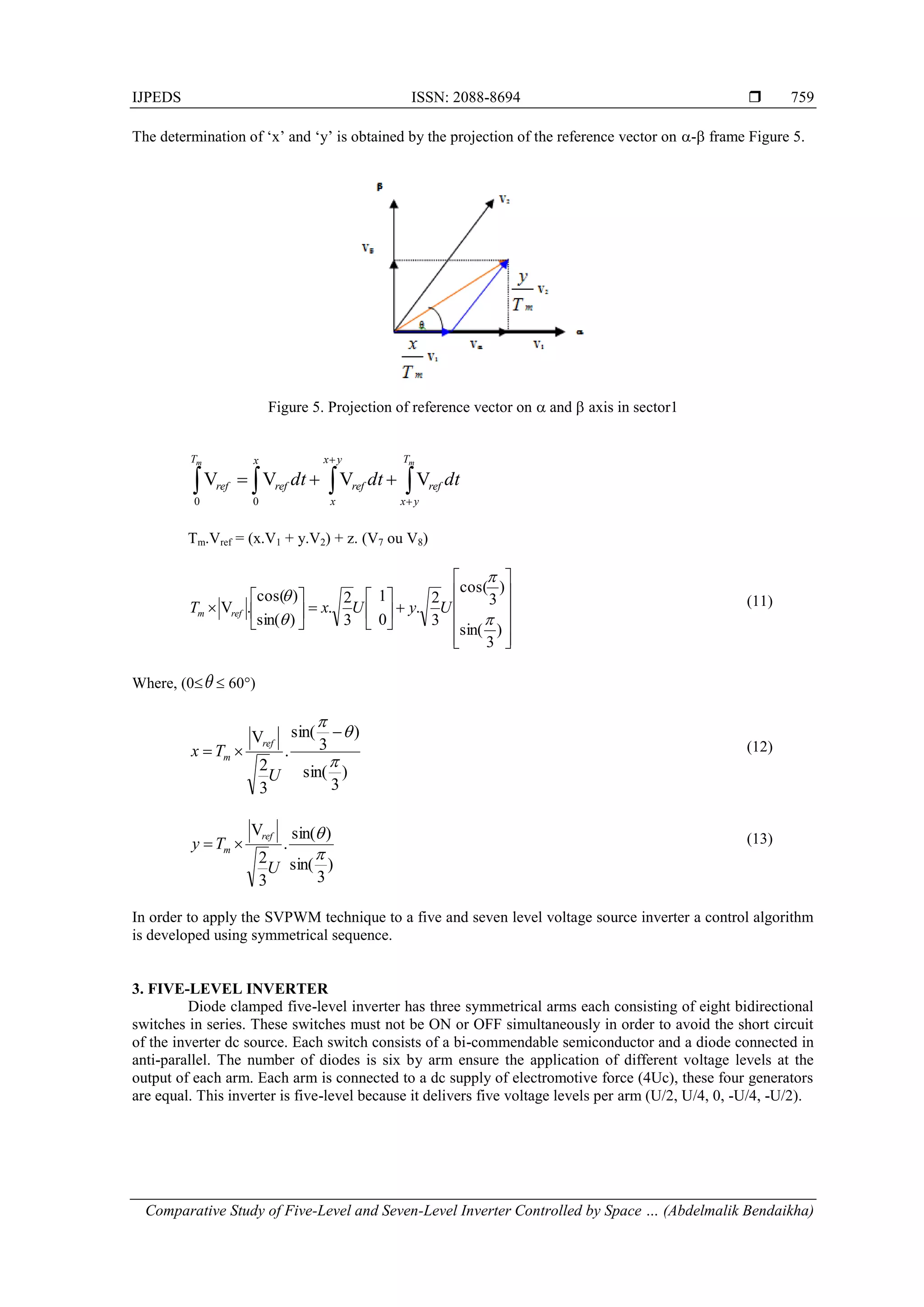
a. Determination of V, V,Vref, and the rotating angle (θ).
b. Application time of adjacent vectors x, y, and z.
c. Determination of the switching time of each switch (Sa,Sb, Sc ,Sa’, Sb’ and Sc’).
From Figure 4,V, V, Vref, and the rotating angle (θ) can be determined as follows:
Figure 4. Voltage vector and its components in (-) frame
V .cos60 cos60
1 1
cos60
2 2
an bn cn
an bn cn
V V V
V V V
V 0. .cos30 .cos30
3 3
0.
2 2
an bn cn
an bn cn
V V V
V V V
Conserving the power transfer (Concordia transformation). The voltage vectors on the (-) axis can then be
described as [10]:
V
V
V
2
3
2
3
0
2
1
2
1
1
3
2
V
V
cn
bn
an
s
s
(6)
2 2
ref
V V V
(7)
1
tan 2
V
g t ft
V
(8)
Where:
f: is the fundamental frequency
The reference vector Vref is estimated over a modulation period Tm, by generating an average vector
determined by the application of inverter adjacent non-zero and zero vectors. Figure 4, illustrates the case
where the reference vector is in sector 1. The application time of adjacent vectors are given as follows:
Tm=x+y+z (9)
0
2
1 V
V
V
V
m
m
m
ref
T
z
T
y
T
x
(10)](https://image.slidesharecdn.com/246762-7149-1-pb-210607015026/75/Comparative-Study-of-Five-Level-and-Seven-Level-Inverter-Controlled-by-Space-Vector-Pulse-Width-Modulation-4-2048.jpg)
![IJPEDS ISSN: 2088-8694
Comparative Study of Five-Level and Seven-Level Inverter Controlled by Space … (Abdelmalik Bendaikha)
765
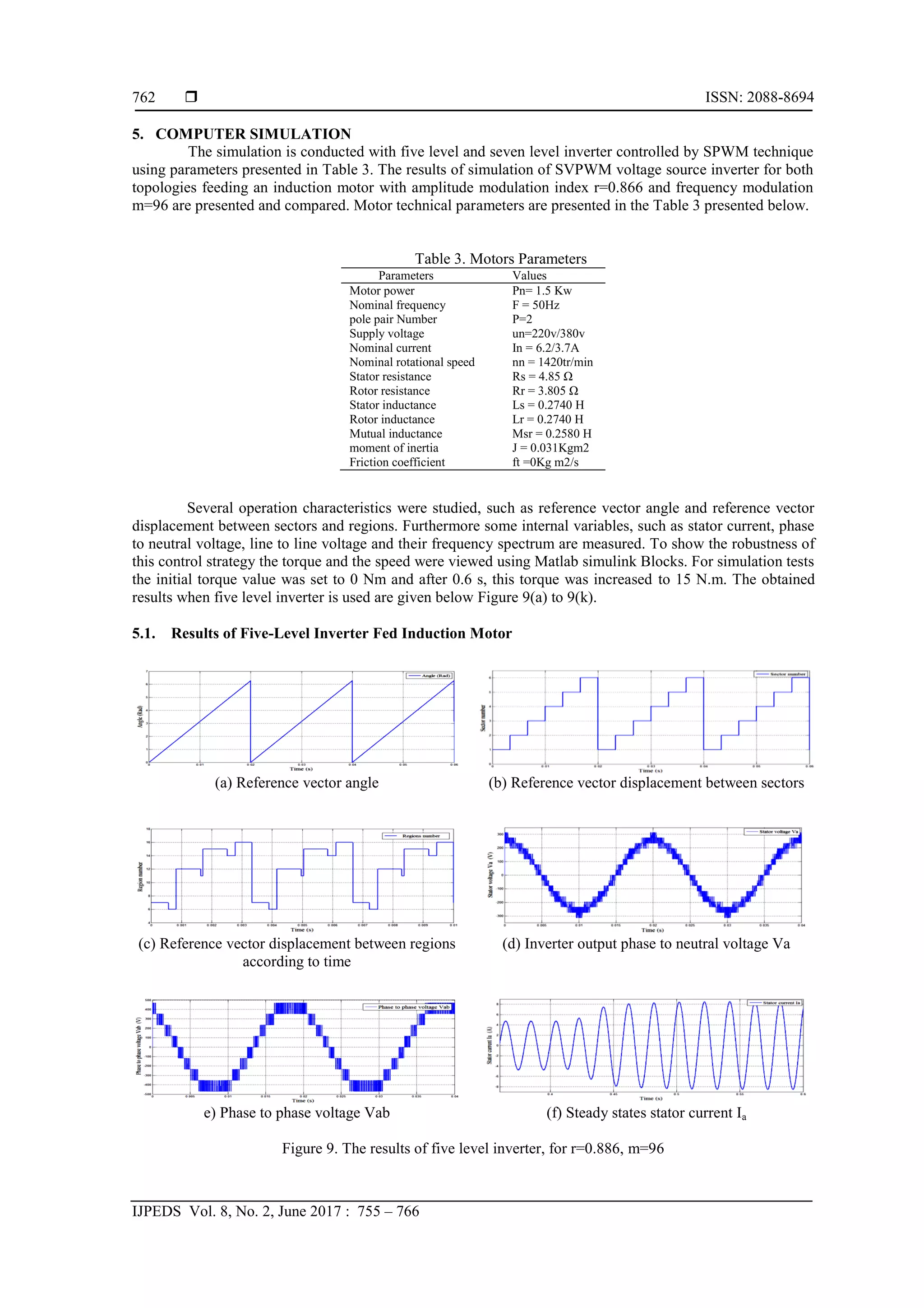
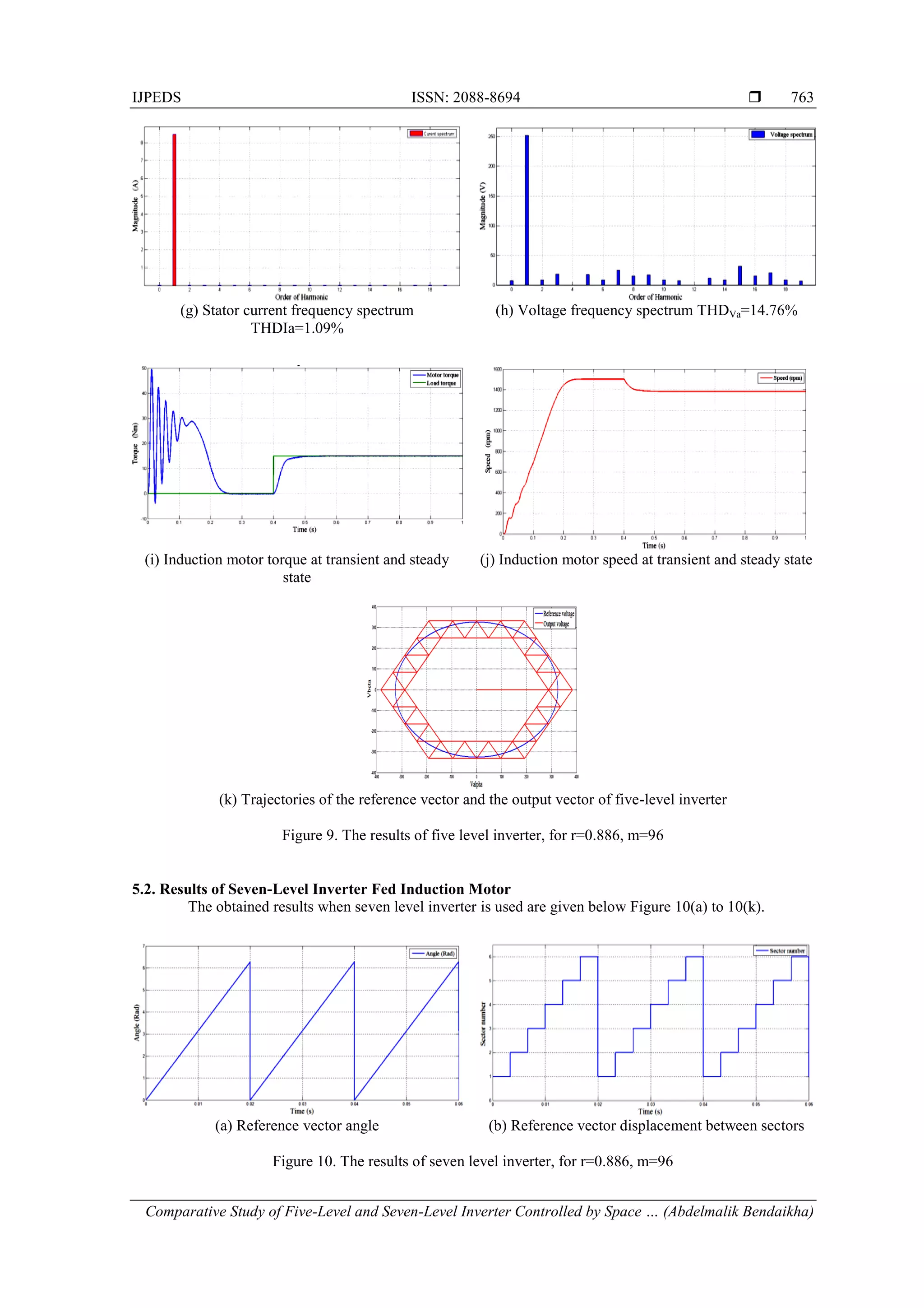
6. RESULTS AND ANALYSIS
The results of the developed algorithm of a five level inverter controlling induction motor are
illustrated in Figure 9(a) to Figure 9(k). The Figure 9(a, b and c) illustrate reference vector angle, reference
vector displacement between sectors and reference vector displacement between regions according to time
respectively.
The phase to neutral voltage (Figure 9(d)), the stator phase current (Figure 9((f)) waveforms and
their frequency spectrum illustrated on Figure 9(g) and Figure 9(h) have THD values equal to (14.76%) and
(1.09%) respectively for an amplitude modulation index r=0.866 and a frequency modulation m=96.
Figure 9.e illustrates phase to phase voltage Vab. Figure 9(k) illustrate Trajectories of the reference vector
and the output vector. The speed curve shown in Figure 9(i) has three sections; transient state section from 0
to 0.29 s, no load operation section from 0.29-0.4 s and a section for load (15 N.m) operation applied at 0.4 s
and the time response is less than 0.15s.
The torque curve presented in Figure 10.j) has three sections; transient state section from 0 to 0.29 s,
no load (0.00 N.m) operation section from 0.29-0.4 s and a section for load (15 N.m) operation applied at 0.4
s and the time response is less than 0.15s. Phase to neutral voltage (Figure 9(d)) has seventeen voltage levels
and phase to phase voltage has nine voltage levels, thus its shape is closer to the sinusoidal shape. Figure 9(k)
illustrates trajectories of the reference vector and the output vector showing that the output vector is tracking
the reference vector.
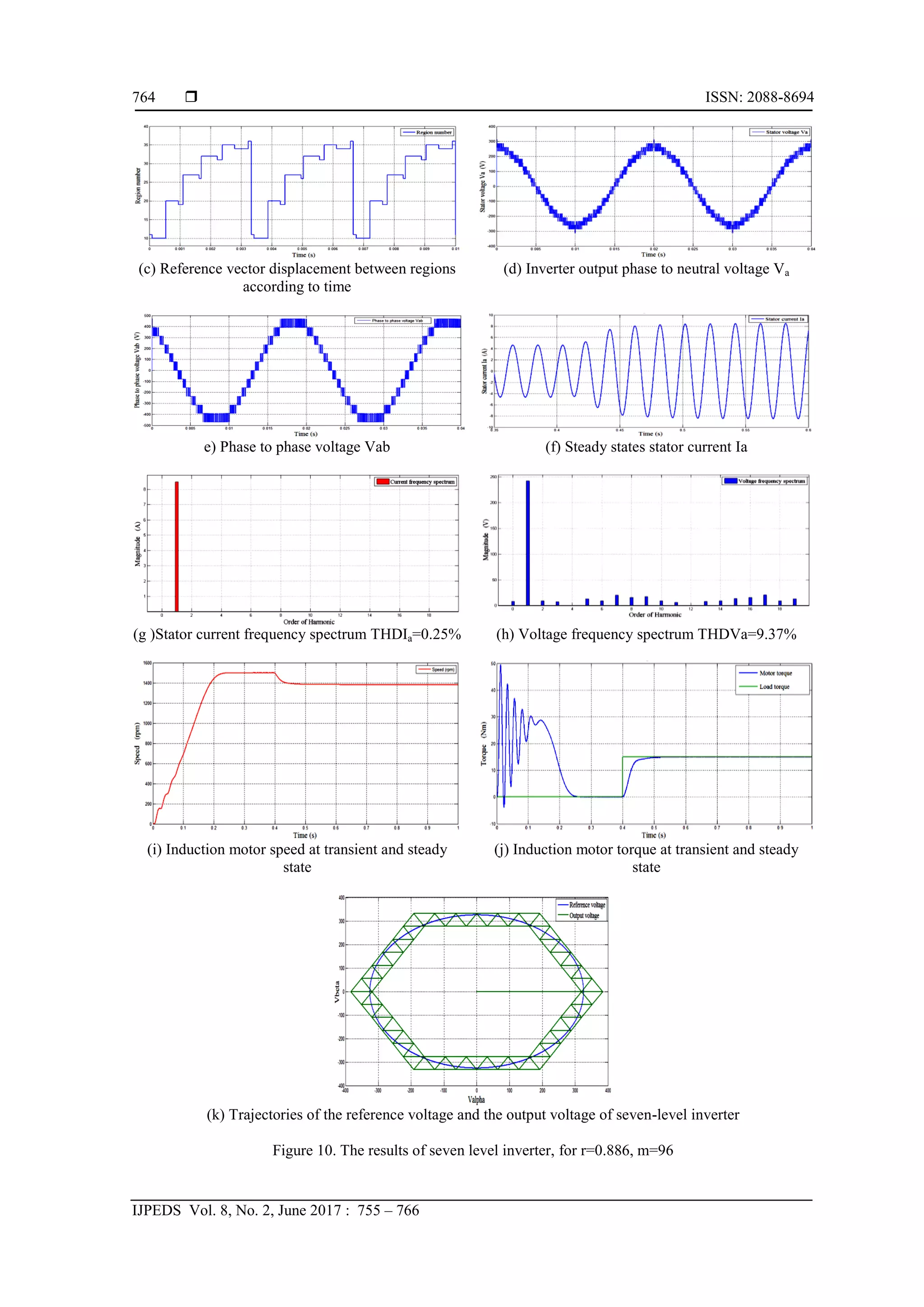
The results when the developed algorithm of a seven level inverter controlling induction motor is
applied are presented in Figure 10(a) to Figure 10(k). The Figure 10(a, b, and c) illustrate reference vector
angle, reference vector displacement between sectors and reference vector displacement between regions
according to time, respectively. Figure 10.e illustrates phase to phase voltage Vab. The phase to neutral
voltage (Figure 10.d), the stator phase current (Figure 10(f)) waveforms and their frequency spectrum
illustrated on Figure 10(h) and Figure 10(g) have THD values equal to (9.37%) and (0.25%) respectively for
an amplitude modulation index r=0.866 and a frequency modulation m=96.
The speed curve shown in Figure 10.i has three sections; transient state section from 0 to 0.25 s, no
load operation section from 0.25-0.4 s and a section for load (15 N.m) operation applied at 0.4 s and the time
response is less than 0.12s. The torque curve presented in Figure 10(j) has three sections; transient state
section from 0 to 0.25 s, no load (0.00 N.m) operation section from 0.25-0.4 s and a section for load (15 N.m)
operation applied at 0.4 s and the time response is less than 0.12s.
Phase to neutral voltage has twenty five voltage levels (Figure 10.d) and phase to phase voltage has
thirteen voltage levels. It can be observed that speed and torque time responses are better when the motor is
fed by seven-level inverter. Therefore, a better speed regulation is obtained. The inverter output current
waveform of seven-level inverter is almost sinusoidal contains less harmonics and less torque fluctuations
thus, a better motor dynamic response is obtained. Figure 10(k) illustrate Trajectories of the reference vector
and the output vector showing that the output vector is tracking the reference vector.
In order to evatuate the SVPWM strategy applied to five and seven level inverter topologies, the
speed and torque curves as well as current and voltage frequency spectrums are compared. The phase to
neutral voltage, the stator phase current waveforms and thefrequency spectrum of five level inverter have
THD values equal to (14.76%) and (1.09%) respectively. The phase to neutral voltage, the stator phase
current waveforms and frequency spectrum of seven level inverter have THD values equal to (9.37%) and
(0.25%) respectively. The results have showed that when seven level inverter is used the harmonic currents
and voltage distortions are reduced and torque fluctuations are less. But the developed algorithm gives
reduced commutation losses when five-level inverter is used because the switching devices number is
reduced. Comparing these results to the results of the literature it can be noticed that THD values of both
current and voltage are well below the obtained values of [1], [11] and IEEE recommendations.
7. CONCLUSION
The present paper has presented a comparative study of multilevel inverter topologies controlled by
space vector PWM feeding an induction motor. The results have showed that seven level inverter gives
reduced harmonics current and voltage distortion and less torque fluctuations. But the commutation losses are
minimized when five-level inverter because the switching devices number is reduced.
The results have showed that the seven-level inverter is the best topology compared to five-level
topology; but it has some disadvantages such as large number of semiconductors devices which involves high
losses compared to other types. This work has allowed understanding the basic principles to design and
simulation of any complex power engineering system. It has served to enhance knowledge of programming,
modeling and power control techniques of induction motors.](https://image.slidesharecdn.com/246762-7149-1-pb-210607015026/75/Comparative-Study-of-Five-Level-and-Seven-Level-Inverter-Controlled-by-Space-Vector-Pulse-Width-Modulation-11-2048.jpg)
![ ISSN: 2088-8694
IJPEDS Vol. 8, No. 2, June 2017 : 755 – 766
766
REFERENCES
[1] Chetanya Gupta, Devbrat Kuanr, Abhishek Varshney, Tahir Khurshaid, Kapil Dev Singh" Harmonic Analysis of
Seven and Nine Level Cascade Multilevel Inverter using Multi-Carrier PWM Technique", IJPEDS, Vol. 5, No. 1,
July 2014, pp. 76~82.
[2] Ayşe Kocalmış, Sedat Sünter, "Simulation of a Space Vector PWM Controller For a Three-Level Voltage-Fed
Inverter Motor Drive", 2006 IEEE, pp 1915-1920.
[3] Samir Kouro, Rafael Bernal, Hernan Miranda, Jose Rodrıguez and Jorge Pontt, "Direct Torque Control With
Reduced Switching Losses for Asymmetric Multilevel Inverter Fed Induction Motor Drives", 2006 IEEE, pp 2441-
2446.
[4] Fouad Berrabaha, Saad Salah, Ali Chebabhi, "SVM technique based on DTC sensorless control optimized by ANN
applied to a double stator asynchronous machine fed by three-level six-phase inverter", The Mediterranean Journal
of Measurement and Control, Vol. 12, No. 2, 2016.
[5] Keliang Zhou and Danwei Wang, "Relationship Between Space-Vector Modulation and Three-Phase Carrier-Based
PWM", IEEE transactions on industrial electronics, vol. 49, no. , February 2002.
[6] K.S. Gayathri Devi, S. Arun, C. Sreeja, "Comparative study on different five level inverter topologies", Electrical
Power and Energy Systems 63 (2014) 363–372.
[7] Mohammad Shadab Mirza, Tufail Mohammad, Qamar Alam, Mohammad Ariffuddin Mallick, "Simulation and
Analysis of a Grid Connected Multi-level Converter Topologies and their Comparison", Journal of Electrical
Systems and Information Technology 1 (2014) 166–174.
[8] S. Umashankar, T. S. Sreedevi, V. G. Nithya, and D. Vijayakumar, "A New 7-Level Symmetric Multilevel Inverter
with Minimum Number of Switches", Volume 2013, Article ID 476876, 9 pages.
[9] M. Valan Rajkumar, P.S. Manoharan, A. Ravi, "Simulation and an experimental investigation of SVPWM technique
on a multilevel voltage source inverter for photovoltaic systems", Electrical Power and Energy Systems
ScienceDirect, Volume 52, November 2013, Pages 116–131.
[10] Gomathi C, Navya Nagath, Veerakumar S,"Sampled Reference Frame Algorithm Based on Space Vector Pulse
Width Modulation for Five Level Cascaded H-Bridge Inverter", Bulletin of Electrical Engineering and Informatics
Vol. 3, No. 2, June 2014, pp. 127~140.
[11] Zulkifilie Bin Ibrahim et al, “Comparative Analysis of PWM Techniques for Three Level Diode Clamped Voltage
Source Inverter ", International Journal of Power Electronics and Drive System (IJPEDS) Vol. 5, No. 1, July 2014,
pp. 15~23.
BIOGRAPHIES OF AUTHORS
Abdelmalik Bendaikha was born in Batna, Algeria, in 1974. He received the Engineer, master’s
degrees in electromechanicalapplied to mining fields from Badji-Mokhtar Annaba, Algeria, in
1997, 2007, respectively. Since 2007, he is a Senior Lecturer with the University of M’sila
Algeria. His research interests are mainly in the area of Measurement, Control, Electronics &
electrical drives
Salah Saad was born in Batna, Algeria, in 1958. He received the Engineer degree in
electromechanical applied to mining fields from Badji-Mokhtar Annaba University Algeria and
the Ph.D. degree from Nottingham University, U.K., in 1983 and 1988, respectively. Since 1988,
he has been a Lecturer, Senior Lecturer, and Professor with Badji-Mokhtar Annaba University
Algeria. He has supervised many graduated and postgraduate student thesis. He has conducted
many researches projects in power electronics applications, electrical ac and dc drives as well as
diagnosis and faults detection in ac machines. His research interests are mainly in the area of
power electronics such as harmonics elimination by active filters, PWM and space vector
modulation control, multilevel inverters, new converter topologies, and vibration sensors. He has
authored or co-authored many journal and conference papers. He has co-authored a book in the
field of signal processing published in Algeria in 1992.](https://image.slidesharecdn.com/246762-7149-1-pb-210607015026/75/Comparative-Study-of-Five-Level-and-Seven-Level-Inverter-Controlled-by-Space-Vector-Pulse-Width-Modulation-12-2048.jpg)