Download to read offline
![Divya Ahirrao et al Int. Journal of Engineering Research and Applications www.ijera.com
ISSN : 2248-9622, Vol. 4, Issue 3( Version 1), March 2014, pp.856-861
www.ijera.com 856 | P a g e
Analysis Of Single Phase Matrix Converter
DivyaAhirrao*, BhagyashriGaware*, PrajaktaKakade*, PratikshaKharade*,
Prof. Sandeep Chawda*
*Department Of Electrical Engineering,BhivrabaiSawant Institute Of Technology & Research, University Of
Pune, Pune, Maharashtra, India
ABSTRACT
This paper presents concept of single phase matrix converter. Single phase matrix converter (SPMC) performs a
function such as frequency changer, rectifier, inverter; chopper. This reduces the need for new converter
hardware. Pulse width modulation (SPWM) techniques are used to calculate the switch duty ratio to synthesis
the output. The simulation of converter is carried out in MATLAB/SIMULINK. Hardware design is obtained
using readily available IC‟s and other components. This paper discusses the new multiple converter for single
phase input using matrix topology using just a single control logic.
Keywords - Chopper, Cyclo-converter, Inverter, Matrix converter, MATLAB/SIMULINK.
I. INTRODUCTION
Power electronic applications have become
very common in modern commercial and industrial
environments particularly in applications of AC-DC
conversions. Traditionally ac and dc conversion
systems are used separately for ac and dc loads.
Currently no system is available to get AC and DC
output simultaneously. Novel concept of multiple
converter means that it can give AC and DC output
simultaneously using single control circuit. For the
implementation of such a multiple converter matrix
topology is used. The Matrix Converter (MC) is an
array of bidirectional switches as the main power
elements, which interconnects directly the Input
supply to the load, without using any dc-link or large
energy storage elements.
The Matrix Converter (MC) is an advanced
circuit topology that offers many advantages such as
the ability to regenerate energy back to the utility,
sinusoidal input and output current and a controllable
input current displacement factor [1]. It has the
potential of affording an “all silicon” solution for
AC-AC conversion, removing the need for reactive
energy storage components used in conventional
rectifier-inverter based systems. The Single-phase
matrix converter (SPMC) was first realized by
Zuckerberger [2]. It has been shown that the SPMC
could be used to operate as a direct AC-AC single-
phase converter [3], DC chopper [4], rectifier [5] &
inverter [6]. In this papera new multiple converters
using matrix topology for allconversions using a
single circuit is presented.
II. SINGLE PHASE MATRIX
CONVERTER
A power electronic system consists of one or
more power electronic converters. The switching
characteristics of power semiconductor devices
permit a power electronic converter to shape the
input power of one form to output power of other
form. Static power converters perform various power
conversion very efficiently. Ac and dc conversion
systems are used separately for ac and dc loads.
For different types of conversion different
circuits are used. But in certain applications like
uninterruptable power supply which converts AC into
DC for charging the batteries using rectifiers and then
converts the stored energy again into AC using
inverter, requires two conversion circuits. Also in
traction different types of motors are employed such
as DC series, DC shunt and AC series which require
conversion of supply. A number of conversion kits
are required in laboratories. This increases the total
cost and also the space requirement.
A recent technology known as single
phase matrix converter is capable of performing all
these conversions. The use of a matrix converter in
the future reduces the need for learning many varying
converter topologies and that is now the subject of
current active research.
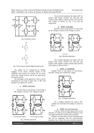
Fig. 1(a) shows a SPMC that requires
four bi-directional switches capable of blocking
voltage and conducting current in both directions.
The common emitter anti-parallel IGBT, with diode
pair is used in absence of bidirectional switch module
as in fig. 1(b). The IGBT was used due to its high
switching capabilities and high current carrying
capacities.
RESEARCH ARTICLE OPEN ACCESS](https://image.slidesharecdn.com/ep4301856861-140419005340-phpapp02/85/Ep4301856861-1-320.jpg)
![Divya Ahirrao et al Int. Journal of Engineering Research and Applications www.ijera.com
ISSN : 2248-9622, Vol. 4, Issue 3( Version 1), March 2014, pp.856-861
www.ijera.com 856 | P a g e
Analysis Of Single Phase Matrix Converter
DivyaAhirrao*, BhagyashriGaware*, PrajaktaKakade*, PratikshaKharade*,
Prof. Sandeep Chawda*
*Department Of Electrical Engineering,BhivrabaiSawant Institute Of Technology & Research, University Of
Pune, Pune, Maharashtra, India
ABSTRACT
This paper presents concept of single phase matrix converter. Single phase matrix converter (SPMC) performs a
function such as frequency changer, rectifier, inverter; chopper. This reduces the need for new converter
hardware. Pulse width modulation (SPWM) techniques are used to calculate the switch duty ratio to synthesis
the output. The simulation of converter is carried out in MATLAB/SIMULINK. Hardware design is obtained
using readily available IC‟s and other components. This paper discusses the new multiple converter for single
phase input using matrix topology using just a single control logic.
Keywords - Chopper, Cyclo-converter, Inverter, Matrix converter, MATLAB/SIMULINK.
I. INTRODUCTION
Power electronic applications have become
very common in modern commercial and industrial
environments particularly in applications of AC-DC
conversions. Traditionally ac and dc conversion
systems are used separately for ac and dc loads.
Currently no system is available to get AC and DC
output simultaneously. Novel concept of multiple
converter means that it can give AC and DC output
simultaneously using single control circuit. For the
implementation of such a multiple converter matrix
topology is used. The Matrix Converter (MC) is an
array of bidirectional switches as the main power
elements, which interconnects directly the Input
supply to the load, without using any dc-link or large
energy storage elements.
The Matrix Converter (MC) is an advanced
circuit topology that offers many advantages such as
the ability to regenerate energy back to the utility,
sinusoidal input and output current and a controllable
input current displacement factor [1]. It has the
potential of affording an “all silicon” solution for
AC-AC conversion, removing the need for reactive
energy storage components used in conventional
rectifier-inverter based systems. The Single-phase
matrix converter (SPMC) was first realized by
Zuckerberger [2]. It has been shown that the SPMC
could be used to operate as a direct AC-AC single-
phase converter [3], DC chopper [4], rectifier [5] &
inverter [6]. In this papera new multiple converters
using matrix topology for allconversions using a
single circuit is presented.
II. SINGLE PHASE MATRIX
CONVERTER
A power electronic system consists of one or
more power electronic converters. The switching
characteristics of power semiconductor devices
permit a power electronic converter to shape the
input power of one form to output power of other
form. Static power converters perform various power
conversion very efficiently. Ac and dc conversion
systems are used separately for ac and dc loads.
For different types of conversion different
circuits are used. But in certain applications like
uninterruptable power supply which converts AC into
DC for charging the batteries using rectifiers and then
converts the stored energy again into AC using
inverter, requires two conversion circuits. Also in
traction different types of motors are employed such
as DC series, DC shunt and AC series which require
conversion of supply. A number of conversion kits
are required in laboratories. This increases the total
cost and also the space requirement.
A recent technology known as single
phase matrix converter is capable of performing all
these conversions. The use of a matrix converter in
the future reduces the need for learning many varying
converter topologies and that is now the subject of
current active research.
Fig. 1(a) shows a SPMC that requires
four bi-directional switches capable of blocking
voltage and conducting current in both directions.
The common emitter anti-parallel IGBT, with diode
pair is used in absence of bidirectional switch module
as in fig. 1(b). The IGBT was used due to its high
switching capabilities and high current carrying
capacities.
RESEARCH ARTICLE OPEN ACCESS](https://image.slidesharecdn.com/ep4301856861-140419005340-phpapp02/75/Ep4301856861-1-2048.jpg)
![Divya Ahirrao et al Int. Journal of Engineering Research and Applications www.ijera.com
ISSN : 2248-9622, Vol. 4, Issue 3( Version 1), March 2014, pp.856-861
www.ijera.com 861 | P a g e
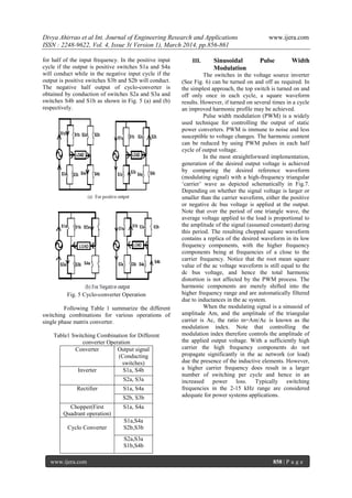
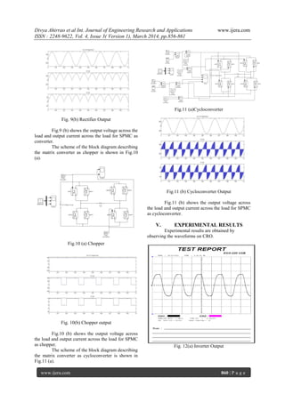
Fig. 12(b) Rectifier Output
Fig. 12(c) Chopper Output
Fig. 12(d) Cycloconverter Output
VI. CONCLUSION
It has been outlined and illustrated that the
single-phase matrix converter can be conceived
designed and realized by suitable switching schemes,
where IGBTs are used for the main power switching
device. When fed from the mains at constant frequency
and amplitude the converter is capable of synthesizing
an output voltage with a fundamental equal to input
frequency multipliers, so that the converter is a
frequency step-up and voltage step-down converter.
From results obtained it has been shown that the SPMC
can have either AC or DC supply input and synthesized
AC or DC output using a well-known PWM technique.
The output waveform has been synthesized using Pulse
Width Modulation.
REFERENCES
[1] S.,Hamzah M.K., “Modelling and
simulation of a single-phase AC-AC matrix
converter using SPWM”, Proc.of student
Conference on Research and Development,
SCOReD 2002, pp. 286-289, July 2002.
[2] Zuckerberger A., Weinstock,
D.andAlexandrovitz A., “Single-phase Matrix
Converter”, IEE Proc. ElectricPower App., pp.
235-240, July 1997.
[3] Idris Z, Hamzah M.K. and Saidon M.F.,
“Implementation of Single-Phase Matrix
Converter as a Direct AC-AC Converter with
Commutation Strategies”, Proc. of 37th
IEEE
Power Electronics Specialists Conference, PESC
„06, pp.1 – 7, 18-22 June 2006.
[4] Idris Z, Noor S.Z.M. and Hamzah M.K., “Safe
Commutation Strategy in Single-phase Matrix
Converter”, Proc. of IEEE Sixth International
Conference PEDS 2005, Kuala Lumpur,
Malaysia, pp. 886-891, 2005.
[5] Baharom R., Hasim A.S.A, Hamzah M.K. and
Omar M.F., “A New Single-Phase Controlled
Rectifier Using Single-Phase Matrix Converter”,
Proc. of first International Power and Energy
Conference PECon 2006, Putrajaya, Malaysia,
pp. 453-459, November 2006.
[6] Hamzah M.K., Noor S.Z.M, and Shukor S.F.A.,
“A New Single-Phase Inverter using Single-
Phase Matrix Converter Topology”, Proc. of first
International Power and Energy Conference
PECon 2006, Putrajaya, Malaysia, pp. 459-464,
November 28-29, 2006
[7] Ajay Kumar Gola and Vineeta Agarwal,
“Implementation of an Efficient Algorithm for a
Single Phase Matrix Converter”, Journal of
Power Electronics, Vol. 9, No. 2, March 2009
[8] Sanjay Mohite, Narayan Pisharoty, “Simulation
and analysis of multiple converter using matrix
topologys”, International Journal of Engineering
Research and Applications (IJERA), Vol. 2,
Issue 3, May-June 2012, pp. 521-526.](https://image.slidesharecdn.com/ep4301856861-140419005340-phpapp02/85/Ep4301856861-6-320.jpg)

This paper presents the concept of a single-phase matrix converter (SPMC), which is capable of performing multiple functions such as acting as a rectifier, inverter, and chopper while reducing the need for additional hardware. The document details the simulation of the converter using MATLAB/Simulink and discusses its efficiency in producing both AC and DC outputs through a single control logic system. The proposed technology demonstrates significant advantages in energy conversion applications by integrating various functionalities into a compact design.