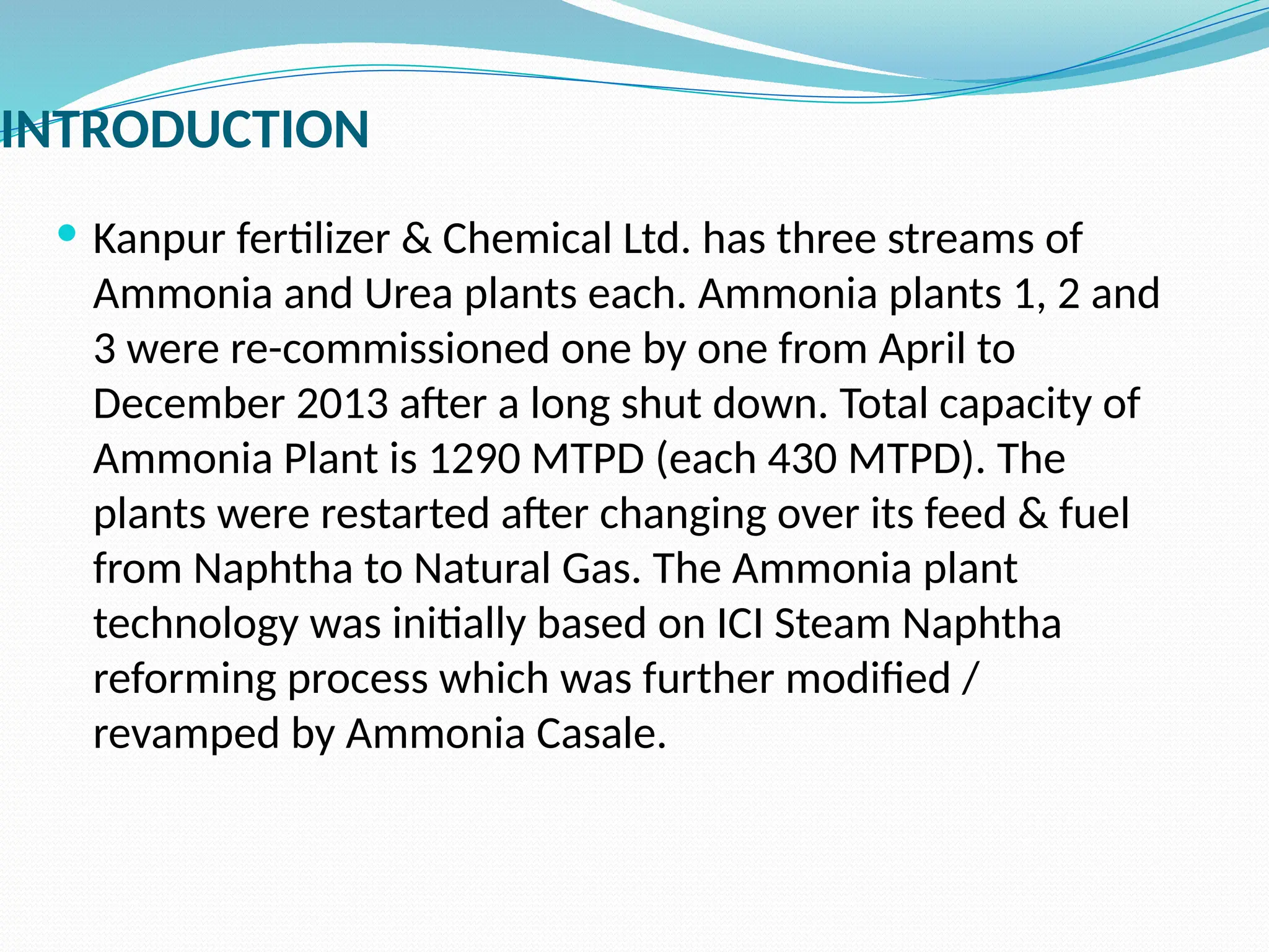
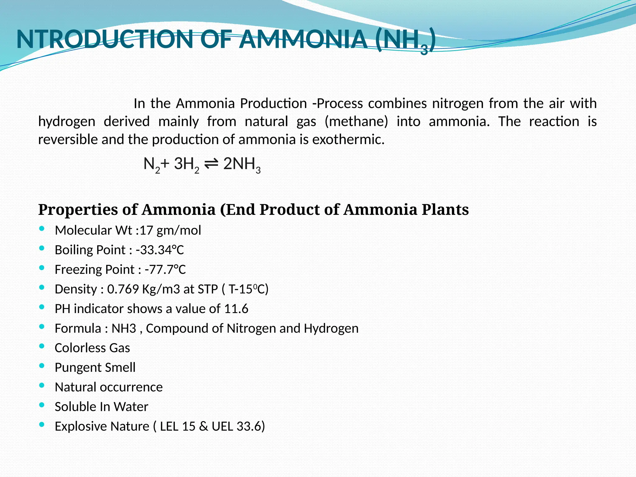
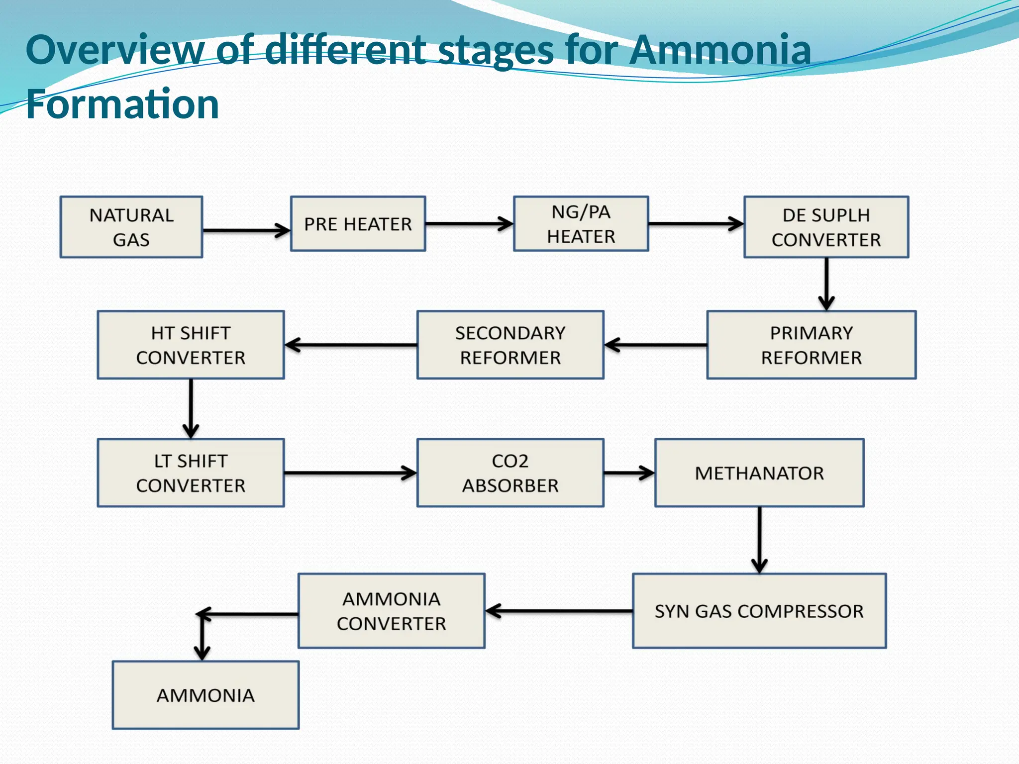
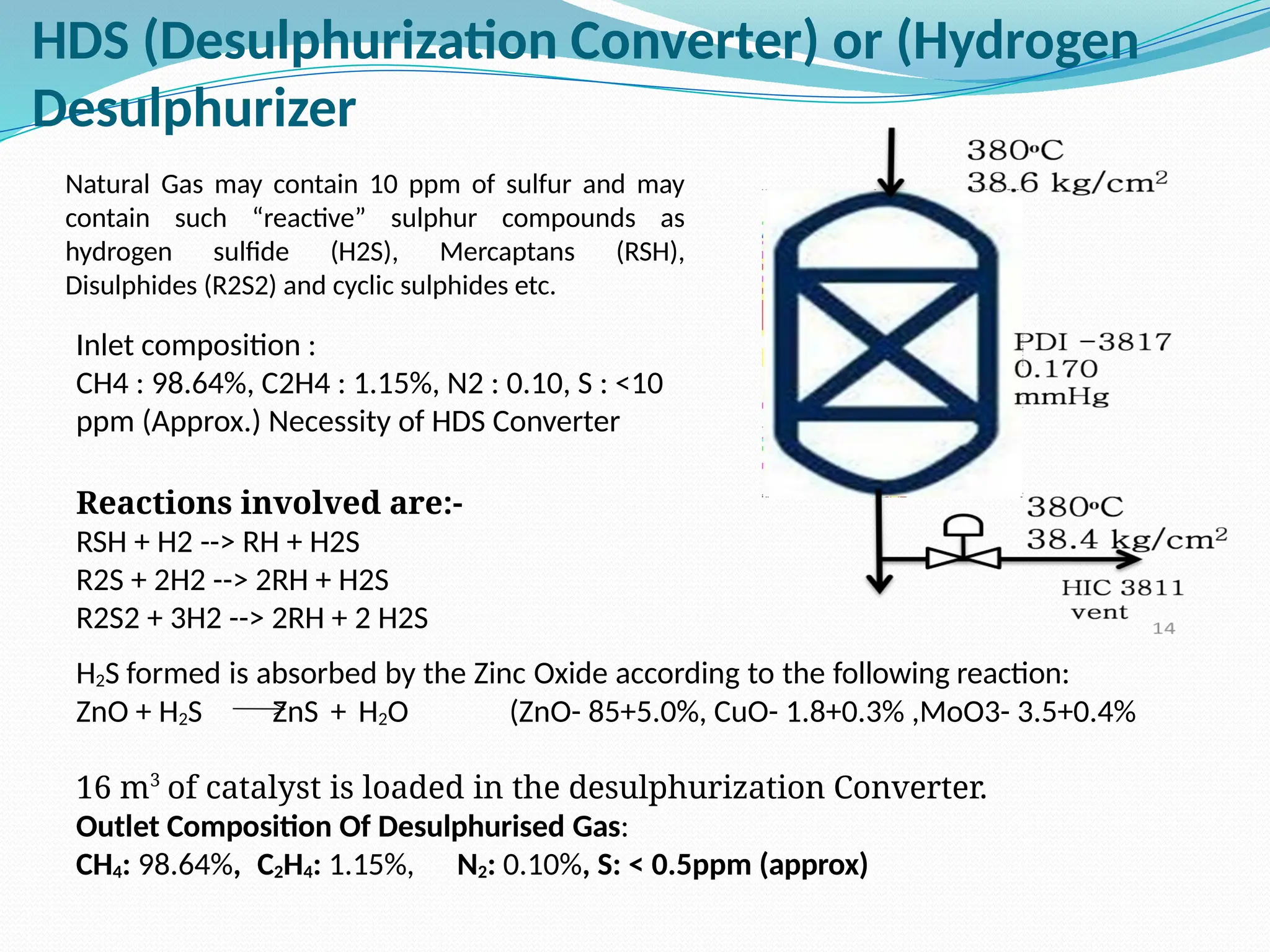
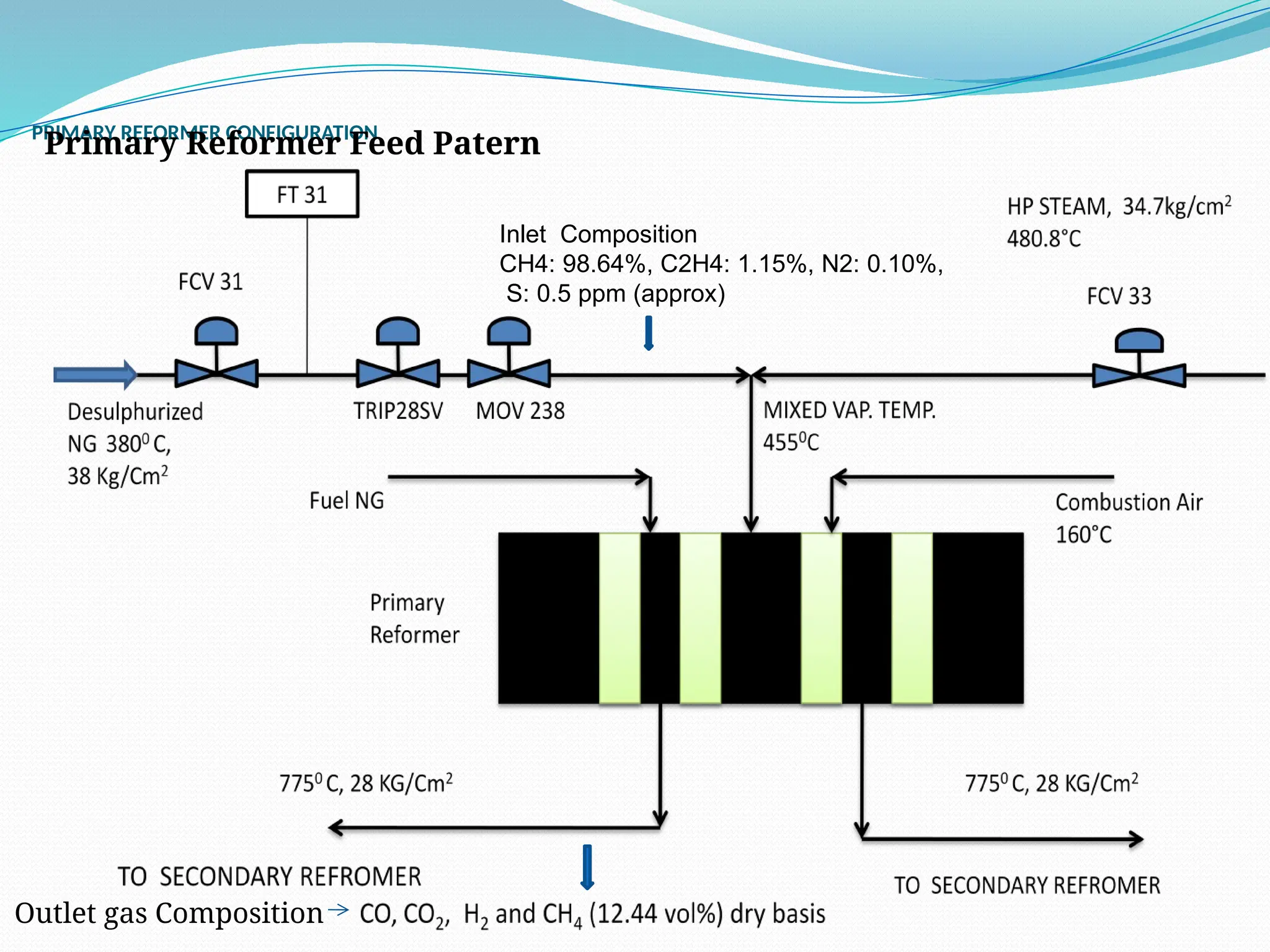
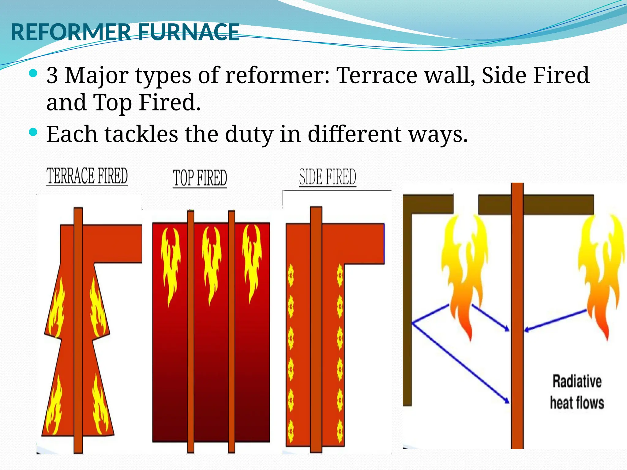
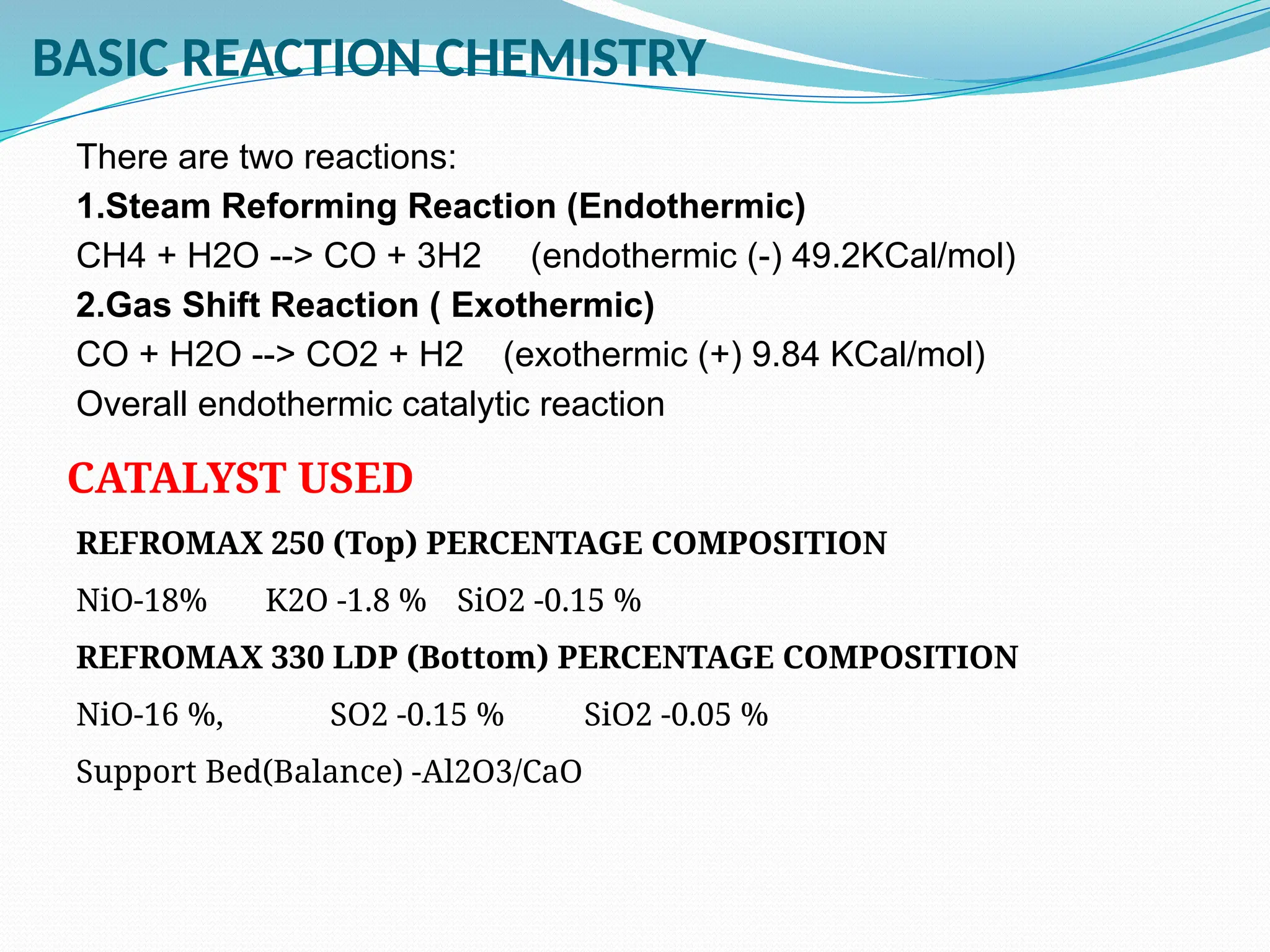
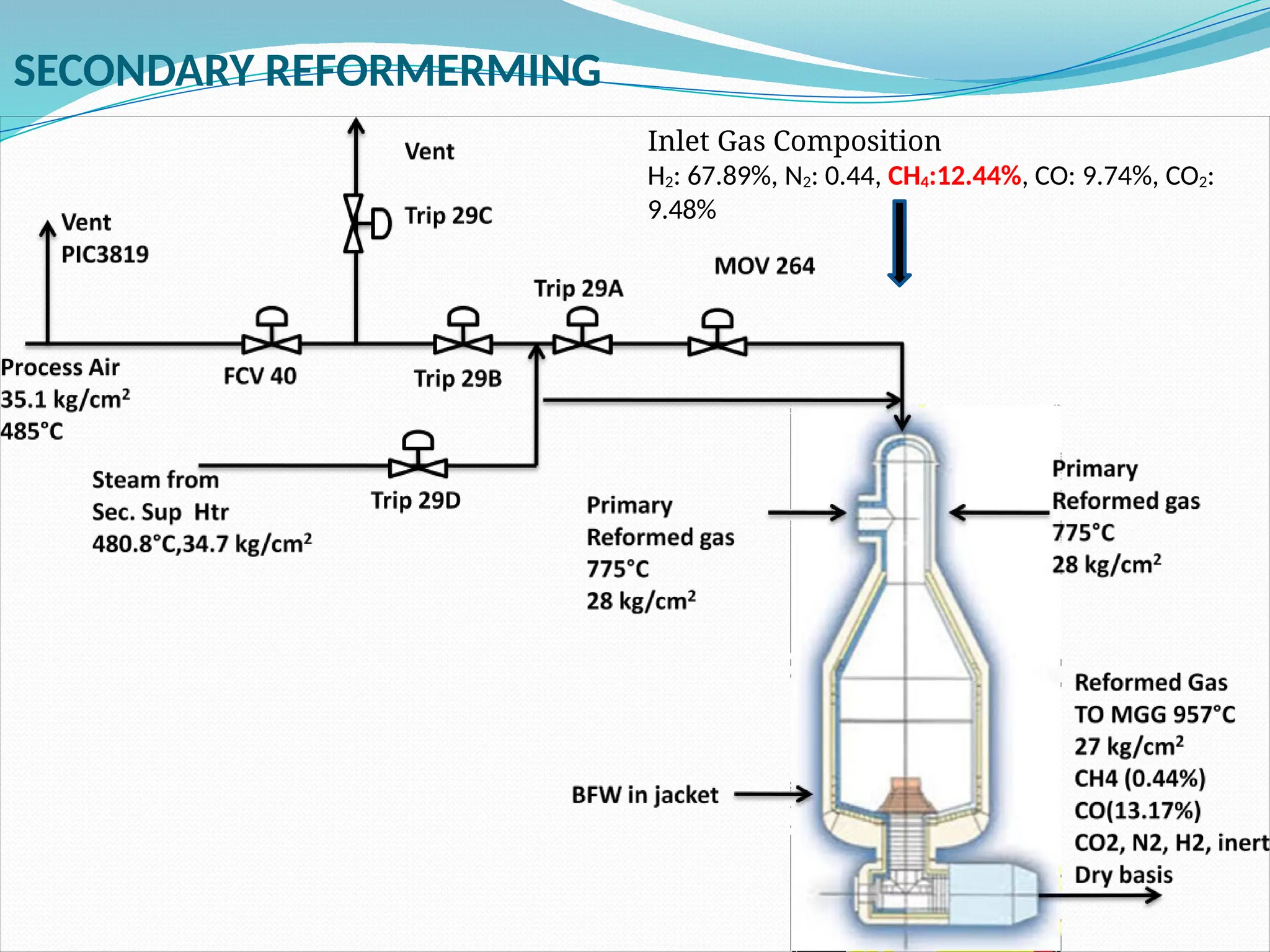
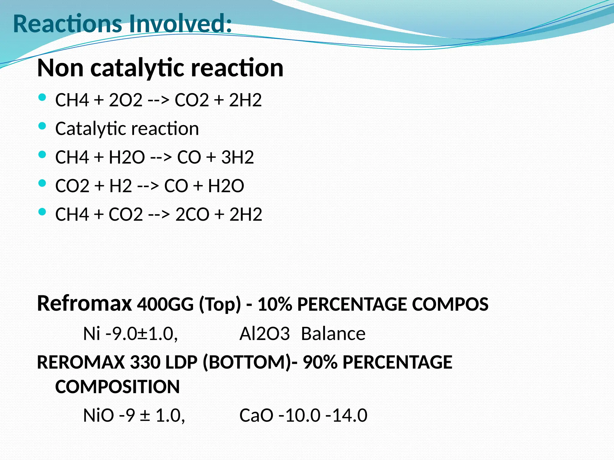
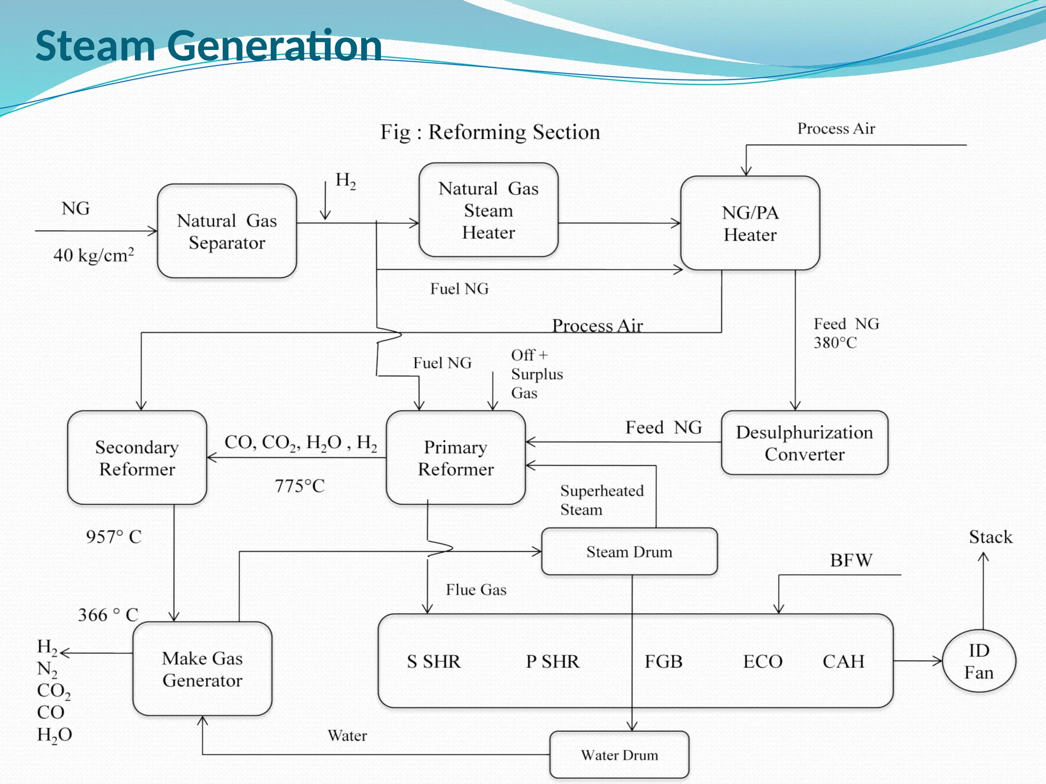
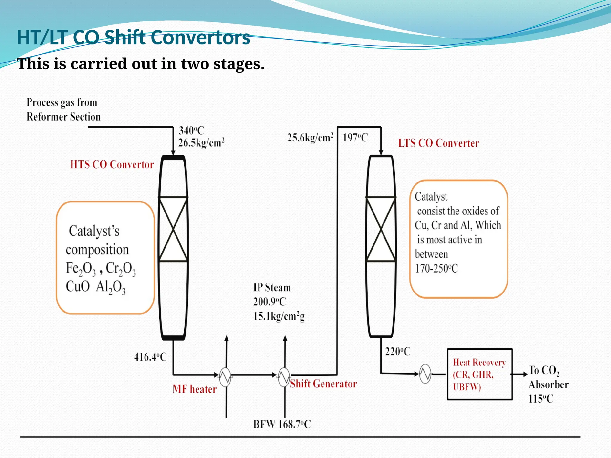
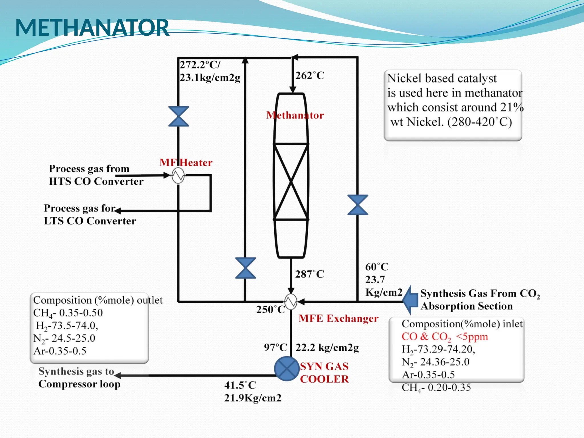
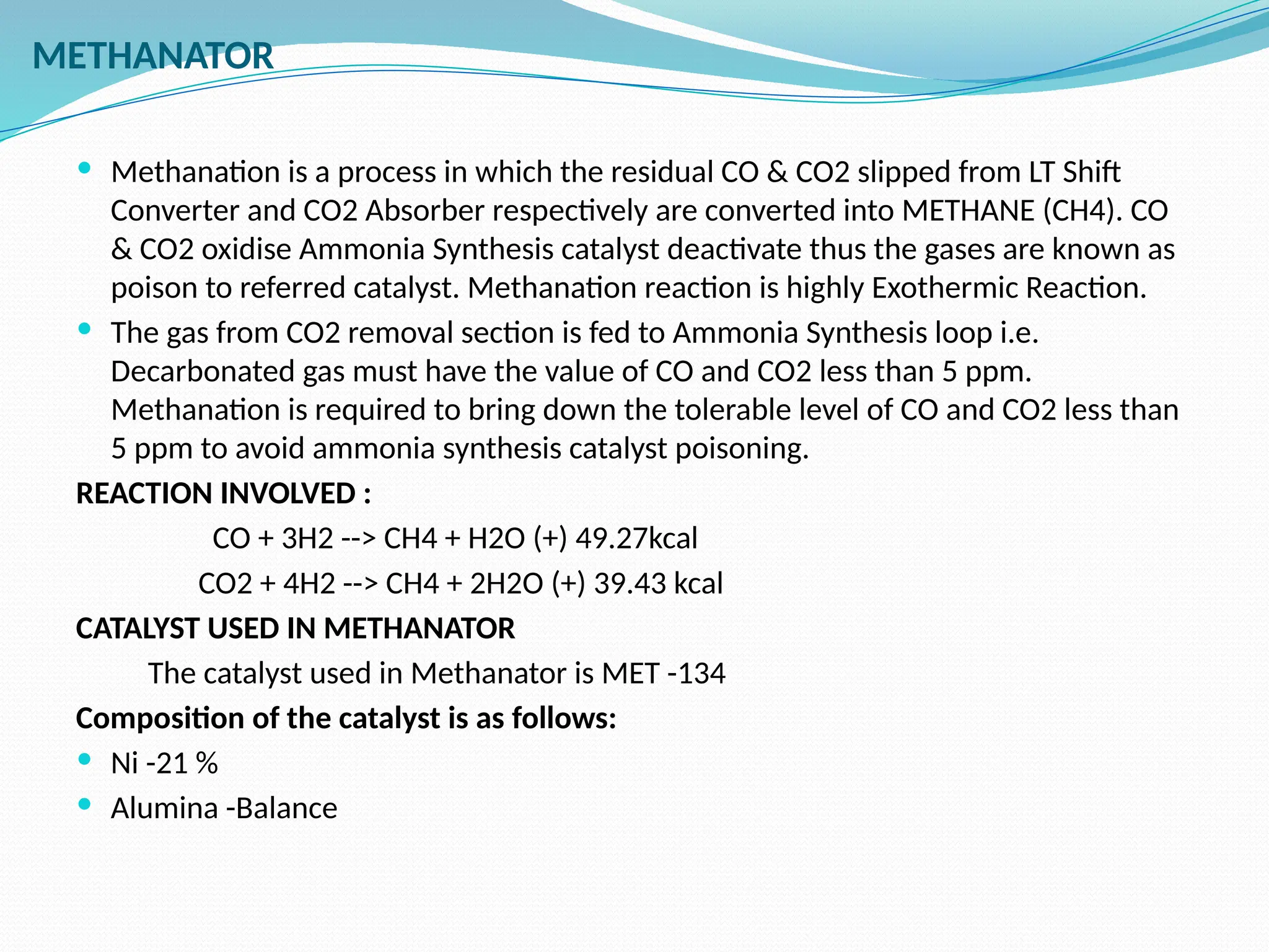
Ammonia
Process
Presented By-
(Technical Services)
INTRODUCTION
 Kanpur fertilizer & Chemical Ltd. has three streams of
Ammonia and Urea plants each. Ammonia plants 1, 2 and
3 were re-commissioned one by one from April to
December 2013 after a long shut down. Total capacity of
Ammonia Plant is 1290 MTPD (each 430 MTPD). The
plants were restarted after changing over its feed & fuel
from Naphtha to Natural Gas. The Ammonia plant
technology was initially based on ICI Steam Naphtha
reforming process which was further modified /
revamped by Ammonia Casale.
NTRODUCTION OF AMMONIA (NH3)
In the Ammonia Production -Process combines nitrogen from the air with
hydrogen derived mainly from natural gas (methane) into ammonia. The reaction is
reversible and the production of ammonia is exothermic.
N2+ 3H2 2NH
⇌ 3
Properties of Ammonia (End Product of Ammonia Plants
 Molecular Wt :17 gm/mol
 Boiling Point : -33.34°C
 Freezing Point : -77.7°C
 Density : 0.769 Kg/m3 at STP ( T-150
C)
 PH indicator shows a value of 11.6
 Formula : NH3 , Compound of Nitrogen and Hydrogen
 Colorless Gas
 Pungent Smell
 Natural occurrence
 Soluble In Water
 Explosive Nature ( LEL 15 & UEL 33.6)
Overview of different stages for Ammonia
Formation
HDS (Desulphurization Converter) or (Hydrogen
Desulphurizer
Natural Gas may contain 10 ppm of sulfur and may
contain such “reactive” sulphur compounds as
hydrogen sulfide (H2S), Mercaptans (RSH),
Disulphides (R2S2) and cyclic sulphides etc.
Reactions involved are:-
RSH + H2 --> RH + H2S
R2S + 2H2 --> 2RH + H2S
R2S2 + 3H2 --> 2RH + 2 H2S
H2S formed is absorbed by the Zinc Oxide according to the following reaction:
ZnO + H2S ZnS + H2O (ZnO- 85+5.0%, CuO- 1.8+0.3% ,MoO3- 3.5+0.4%
16 m3
of catalyst is loaded in the desulphurization Converter.
Outlet Composition Of Desulphurised Gas:
CH4: 98.64%, C2H4: 1.15%, N2: 0.10%, S: < 0.5ppm (approx)
Inlet composition :
CH4 : 98.64%, C2H4 : 1.15%, N2 : 0.10, S : <10
ppm (Approx.) Necessity of HDS Converter
PRIMARY REFORMER CONFIGURATION
Primary Reformer Feed Patern
Inlet Composition
CH4: 98.64%, C2H4: 1.15%, N2: 0.10%,
S: 0.5 ppm (approx)
Outlet gas Composition
REFORMER FURNACE
 3 Major types of reformer: Terrace wall, Side Fired
and Top Fired.
 Each tackles the duty in different ways.
BASIC REACTION CHEMISTRY
There are two reactions:
1.Steam Reforming Reaction (Endothermic)
CH4 + H2O --> CO + 3H2 (endothermic (-) 49.2KCal/mol)
2.Gas Shift Reaction ( Exothermic)
CO + H2O --> CO2 + H2 (exothermic (+) 9.84 KCal/mol)
Overall endothermic catalytic reaction
CATALYST USED
REFROMAX 250 (Top) PERCENTAGE COMPOSITION
NiO-18% K2O -1.8 % SiO2 -0.15 %
REFROMAX 330 LDP (Bottom) PERCENTAGE COMPOSITION
NiO-16 %, SO2 -0.15 % SiO2 -0.05 %
Support Bed(Balance) -Al2O3/CaO
SECONDARY REFORMERMING
Inlet Gas Composition
H2: 67.89%, N2: 0.44, CH4:12.44%, CO: 9.74%, CO2:
9.48%
Reactions Involved:
Non catalytic reaction
 CH4 + 2O2 --> CO2 + 2H2
 Catalytic reaction
 CH4 + H2O --> CO + 3H2
 CO2 + H2 --> CO + H2O
 CH4 + CO2 --> 2CO + 2H2
Refromax 400GG (Top) - 10% PERCENTAGE COMPOS
Ni -9.0±1.0, Al2O3 Balance
REROMAX 330 LDP (BOTTOM)- 90% PERCENTAGE
COMPOSITION
NiO -9 ± 1.0, CaO -10.0 -14.0
Steam Generation
HT/LT CO Shift Convertors
This is carried out in two stages.
HIGH TEMPERATURE SHIFT
HTS Role: Conversion of CO to water gas.
REACTION INVOLVED :
CO + H2O --> CO2 + H2 (+) 890.3 KJ
The above reaction is called SHIFT REACTION.
PERCENTAGE COMPOSITION
 Chromium Oxide 8 %
 Copper Oxide 1.8 %
 Ferric Oxide Balance
LOW TEMPERATURE SHIFT CONVERTER
CO is converted to CO2 at Low temperature from 2.89% to 0.21%.
Another shift converter for CO conversion of residual CO after HTS.
REACTION INVOLVED :
An Exothermic reaction which occurs in this section is:
CO + H2O CO2 + H2 (+) 890.3 KJ
CATALYST USED: SHIFTMAX 210
 ZnO -47 ± 3.0
 Copper Oxide (CuO) -1.8
 Alumina Balance
INLET COMPOSITION OF
REFOMERED GAS:
CH4: 0.44%,
CO2: 7.09%,
CO: 13.7 %,
N2: 22.75%,
H2: 56.25 %,
Ar: 0.29%
OUTLET COMPOSITION
SHIFT GAS:
CH4: 0.4 %,
CO 2: 15.52%,
CO: 2.89 %,
N2 :20.7 %,
H2 :60.23%,
Ar: 0.26%
LOW TEMPERATURE SHIFT CONVERTER
CO is converted to CO2 at Low temperature from 2.89% to 0.21%.
Another shift converter for CO conversion of residual CO after HTS.
REACTION INVOLVED :
An Exothermic reaction which occurs in this section is:
CO + H2O CO2 + H2 (+) 890.3 KJ
Operating Condition:
 Inlet pressure: 25.6kg/cm2
 Outlet pressure: 25.5kg/cm2
 Inlet temperature: 197oC
 Outlet temperature: 220oC
CATALYST USED: SHIFTMAX 210
 ZnO -47 ± 3.0
 Copper Oxide (CuO) -1.8
 Alumina Balance
Temperature reduction is required before passing converted gas From HTS to
LTS and from LTS to CO2 Absorber; therefore ∆T is used to gain the heat
for steam generation and heat utilization in the process
HTs
 MF Heater: Gas exit HTS is used to heat the Methanator inlet gas from
250ºC to 272.2ºC.
 Shift Generator : MF Heater exit gas is used to generate IP steam exported
to Urea Plant and converted gas cools down to 209.2ºC.
LTs
 Condensate Reboiler: The converted gas heats condensate to 126ºC in
Condensate Reboiler and in turn cools down from 220ºC to 160ºC.
 Gas Heated Reboiler: It is vertical Thermo-siphon boiler attached to HP
Regenerator. In reboiler, process gas enters in tube at 160ºC and heats the
regenerator solution. The gas exits at 135ºC.
 UBFW Heater: The final in this series is horizontal single tube plate
exchanger with a bellows in the shell. In this heater, process gas heats DM
Water to 112ºC and process gas exits at 115°C.
Heat Recovery from Converted gas
CO2 ABSORBER
 Role of Absorber: Absorption of CO2
METHODS FOR REMOVAL OF CO2
 Monoethanolamine
 Benfield Solution (Hot Potassium carbonate)
 Giamarko Vetrocoke
 SOLUTION USED
 Benfield Solution: K2CO3 -26-28%, V2O5 – 0.4 %( approx.), Act -1 – 0.15~0.20%
 REACTION MECHANISM
 Inlet temperature: 115°C
 Outlet temperature: 60°C
 Reaction pressure: 24 kg/cm2g
 The solvent used for CO2 absorption is a K2CO3
 Vanadium pent oxide (V2O5) is added in solution as corrosion inhibitor.
 ACT-1 is used as promoter
Reactions involved
 R2NH (DEA) + CO2 --> R2NCOOH
 R2NCOOH +K2CO3+H2O --> 2KHCO3+R2NH
K2CO3+CO2+H2O --> 2KHCO3 (OVERALL R
OUTLET COMPOSITION
CH4 - 0.47%, H2 -74.4%, N2 – 24.51%, CO - 0.26%, CO2 – <500 ppm EACTION
Regeneration
 Absorber bottom solution is called rich solution because it is at a saturated solubility level on absorbing CO2
from process gas at prevailing pressure and temperature conditions.
 Rich solution is passed through LV-35A to HP & LP Regeneration section to regenerate solution on release of
CO2. Regenerated CO2 obtained is used as reactant in production of urea.
 Finally regenerated solution from HP Regenerator and LP Regenerator is pumped to CO2 Absorber as lean
and semi-lean solutions respectively.
Regeneration is physical Reaction
 2KHCO3 ↔ K2CO3 + CO2 + H2O
 Above reaction occurs in LP and HP Regeneration column and operability condition is
LP Regenerator HP Regenerator
 Top Pressure: 0.21 kg/cm2g Top Pressure: 1.2 kg/cm2g
 Bottom Temperature: 108˚C Bottom Temperature: 128˚C
METHANATOR
METHANATOR
 Methanation is a process in which the residual CO & CO2 slipped from LT Shift
Converter and CO2 Absorber respectively are converted into METHANE (CH4). CO
& CO2 oxidise Ammonia Synthesis catalyst deactivate thus the gases are known as
poison to referred catalyst. Methanation reaction is highly Exothermic Reaction.
 The gas from CO2 removal section is fed to Ammonia Synthesis loop i.e.
Decarbonated gas must have the value of CO and CO2 less than 5 ppm.
Methanation is required to bring down the tolerable level of CO and CO2 less than
5 ppm to avoid ammonia synthesis catalyst poisoning.
REACTION INVOLVED :
CO + 3H2 --> CH4 + H2O (+) 49.27kcal
CO2 + 4H2 --> CH4 + 2H2O (+) 39.43 kcal
CATALYST USED IN METHANATOR
The catalyst used in Methanator is MET -134
Composition of the catalyst is as follows:
 Ni -21 %
 Alumina -Balance
SYNGAS COMPRESSOR
A reciprocating compressor or piston compressor is a positive-displacement
compressor that uses pistons driven by a crankshaft to deliver gases at high
pressure
There are two Reciprocating compressors for each plant.
 3 stage compressor and 1 recirculator stage.
 1st, 2nd and circulator stages are double acting.
 3rd stage is single acting (with balance line to minimize vibrations).
 Water cooled jackets are provided to each stage.
Process Air Compressor
NGPA
Brief Process Description of Ammonia Synthesis and Recovery Section:
Compression: Syn gas reciprocating compressor comprises of 3 Stages and a recirculation
stage. The makeup gas from 3rd stage discharge joins circulator discharge and enters
the loop at a pressure of 269 Kg/cm2.
Chilling system: Exchangers are provided for chilling the gas after compressor delivery for
water removal that is poison for Converter Catalyst. Chilling effect is provided with the
help of Liquid
Ammonia for making the gas free of moisture. Ammonia present in the incoming gas
liquefies arresting water vapours and dehumidifies the circulating gas.
NH3 Convertor: Ammonia Casale’s exclusive Axial Radial 3-bed convertor is installed for
ammonia conversion from Syn-gas. The converter inlet/exit gas contains 4.31/20.56 %
of ammonia.
Waste Heat Recovery Boiler: Converter exit gas is sent to Waste heat Boiler for heat
recovery by reducing its temperature from 320 – 220°C. The heat is utilized to generate
IP steam. Steam is generated at a pressure of 16 Kg/cm2g.
BFW heater: The heat of Converted gas is further utilized to heat Boiler feed water to
reduce gas temperature to 128°C.
Hot Gas/Gas Exchanger: The low grade heat in the converter gas is used to heat incoming
gas going to converter. The converted gas temperature is brought down to 70 °C.
Water Cooler: The unrecoverable heat is sunk into cooling water and temperature is
brought down to 37 °C to liquefy ammonia.
 Primary catch pot: Liquid ammonia condensed in effluent cooler flows to catch
pot along with the un-reacted gas is separated here. Liquid ammonia is sent to
LDV and vapours are sent to re-circulator section of compressor and an
optimum purge from the loop is maintained to keep the inert level with in the
permissible limits to avoid reduction in Ammonia yield and wastage of useful
gas.
 Purge gas chiller: The ammonia collected in the bottom of purge gas chiller is
sent back to primary Catch Pot. The purge gas from Purge gas chiller is sent to
HP absorber for ammonia recovery and further to primary reformer fuel
system.
 Oil Filter: Removes oil from the gas carried over from the compressor, if oil is
carried further into the convertor then oil will vaporize releasing the sulphur
compounds causing catalyst damage. Furthermore oil also acts as poison to the
catalyst.
 Recycle interchanger: Cools down the gas going to chiller by exchanging cold
from the out coming gas of the chiller. This exchanger mainly known as cold
gas/gas exchanger also.
 Recycle chiller: Heat Exchanger used for chilling the stream to the convertor by
using liquid ammonia for knocking the water by means of condensing ammonia
in the system.
 Secondary Catch pot : Used for removing the ammonia and moisture from the
system .
NH3 Converter:
 Ammonia Casale’s Patented Axial Radial Flow Converter
with 3 catalyst Beds with 1 cold Shot , 1 quench and 1
Bottom Exchanger By-Pass valves . Major flow of Gas is
Radial so that the Pressure Drop can be reduced.
 1st Bed inlet/outlet Temperature: 379 / 516 °C
 2nd Bed inlet/outlet Temperature : 421 / 495 °C
 3rd Bed inlet/outlet Temperature : 412 / 460 °C
 Oxidised iron is used as Catalyst. Oxygen is removed during
reduction without shrinkage. This process of reduction with
hydrogen (The reducing gas) produces metallic iron which
is extremely porous and suitable to convert synthesis gas
mixture under high pressure and temperature to Ammonia.
Flow Diagram in Howden Compressor
Ammonia Recovery Flow
Ammonia Recovery Section
Thank You

Ammonia Process Presentation with proper pfd and description , optimisation

  • 1.
  • 2.
    INTRODUCTION  Kanpur fertilizer& Chemical Ltd. has three streams of Ammonia and Urea plants each. Ammonia plants 1, 2 and 3 were re-commissioned one by one from April to December 2013 after a long shut down. Total capacity of Ammonia Plant is 1290 MTPD (each 430 MTPD). The plants were restarted after changing over its feed & fuel from Naphtha to Natural Gas. The Ammonia plant technology was initially based on ICI Steam Naphtha reforming process which was further modified / revamped by Ammonia Casale.
  • 3.
    NTRODUCTION OF AMMONIA(NH3) In the Ammonia Production -Process combines nitrogen from the air with hydrogen derived mainly from natural gas (methane) into ammonia. The reaction is reversible and the production of ammonia is exothermic. N2+ 3H2 2NH ⇌ 3 Properties of Ammonia (End Product of Ammonia Plants  Molecular Wt :17 gm/mol  Boiling Point : -33.34°C  Freezing Point : -77.7°C  Density : 0.769 Kg/m3 at STP ( T-150 C)  PH indicator shows a value of 11.6  Formula : NH3 , Compound of Nitrogen and Hydrogen  Colorless Gas  Pungent Smell  Natural occurrence  Soluble In Water  Explosive Nature ( LEL 15 & UEL 33.6)
  • 4.
    Overview of differentstages for Ammonia Formation
  • 5.
    HDS (Desulphurization Converter)or (Hydrogen Desulphurizer Natural Gas may contain 10 ppm of sulfur and may contain such “reactive” sulphur compounds as hydrogen sulfide (H2S), Mercaptans (RSH), Disulphides (R2S2) and cyclic sulphides etc. Reactions involved are:- RSH + H2 --> RH + H2S R2S + 2H2 --> 2RH + H2S R2S2 + 3H2 --> 2RH + 2 H2S H2S formed is absorbed by the Zinc Oxide according to the following reaction: ZnO + H2S ZnS + H2O (ZnO- 85+5.0%, CuO- 1.8+0.3% ,MoO3- 3.5+0.4% 16 m3 of catalyst is loaded in the desulphurization Converter. Outlet Composition Of Desulphurised Gas: CH4: 98.64%, C2H4: 1.15%, N2: 0.10%, S: < 0.5ppm (approx) Inlet composition : CH4 : 98.64%, C2H4 : 1.15%, N2 : 0.10, S : <10 ppm (Approx.) Necessity of HDS Converter
  • 6.
    PRIMARY REFORMER CONFIGURATION PrimaryReformer Feed Patern Inlet Composition CH4: 98.64%, C2H4: 1.15%, N2: 0.10%, S: 0.5 ppm (approx) Outlet gas Composition
  • 7.
    REFORMER FURNACE  3Major types of reformer: Terrace wall, Side Fired and Top Fired.  Each tackles the duty in different ways.
  • 8.
    BASIC REACTION CHEMISTRY Thereare two reactions: 1.Steam Reforming Reaction (Endothermic) CH4 + H2O --> CO + 3H2 (endothermic (-) 49.2KCal/mol) 2.Gas Shift Reaction ( Exothermic) CO + H2O --> CO2 + H2 (exothermic (+) 9.84 KCal/mol) Overall endothermic catalytic reaction CATALYST USED REFROMAX 250 (Top) PERCENTAGE COMPOSITION NiO-18% K2O -1.8 % SiO2 -0.15 % REFROMAX 330 LDP (Bottom) PERCENTAGE COMPOSITION NiO-16 %, SO2 -0.15 % SiO2 -0.05 % Support Bed(Balance) -Al2O3/CaO
  • 9.
    SECONDARY REFORMERMING Inlet GasComposition H2: 67.89%, N2: 0.44, CH4:12.44%, CO: 9.74%, CO2: 9.48%
  • 10.
    Reactions Involved: Non catalyticreaction  CH4 + 2O2 --> CO2 + 2H2  Catalytic reaction  CH4 + H2O --> CO + 3H2  CO2 + H2 --> CO + H2O  CH4 + CO2 --> 2CO + 2H2 Refromax 400GG (Top) - 10% PERCENTAGE COMPOS Ni -9.0±1.0, Al2O3 Balance REROMAX 330 LDP (BOTTOM)- 90% PERCENTAGE COMPOSITION NiO -9 ± 1.0, CaO -10.0 -14.0
  • 11.
  • 12.
    HT/LT CO ShiftConvertors This is carried out in two stages.
  • 13.
    HIGH TEMPERATURE SHIFT HTSRole: Conversion of CO to water gas. REACTION INVOLVED : CO + H2O --> CO2 + H2 (+) 890.3 KJ The above reaction is called SHIFT REACTION. PERCENTAGE COMPOSITION  Chromium Oxide 8 %  Copper Oxide 1.8 %  Ferric Oxide Balance LOW TEMPERATURE SHIFT CONVERTER CO is converted to CO2 at Low temperature from 2.89% to 0.21%. Another shift converter for CO conversion of residual CO after HTS. REACTION INVOLVED : An Exothermic reaction which occurs in this section is: CO + H2O CO2 + H2 (+) 890.3 KJ CATALYST USED: SHIFTMAX 210  ZnO -47 ± 3.0  Copper Oxide (CuO) -1.8  Alumina Balance INLET COMPOSITION OF REFOMERED GAS: CH4: 0.44%, CO2: 7.09%, CO: 13.7 %, N2: 22.75%, H2: 56.25 %, Ar: 0.29% OUTLET COMPOSITION SHIFT GAS: CH4: 0.4 %, CO 2: 15.52%, CO: 2.89 %, N2 :20.7 %, H2 :60.23%, Ar: 0.26%
  • 14.
    LOW TEMPERATURE SHIFTCONVERTER CO is converted to CO2 at Low temperature from 2.89% to 0.21%. Another shift converter for CO conversion of residual CO after HTS. REACTION INVOLVED : An Exothermic reaction which occurs in this section is: CO + H2O CO2 + H2 (+) 890.3 KJ Operating Condition:  Inlet pressure: 25.6kg/cm2  Outlet pressure: 25.5kg/cm2  Inlet temperature: 197oC  Outlet temperature: 220oC CATALYST USED: SHIFTMAX 210  ZnO -47 ± 3.0  Copper Oxide (CuO) -1.8  Alumina Balance
  • 15.
    Temperature reduction isrequired before passing converted gas From HTS to LTS and from LTS to CO2 Absorber; therefore ∆T is used to gain the heat for steam generation and heat utilization in the process HTs  MF Heater: Gas exit HTS is used to heat the Methanator inlet gas from 250ºC to 272.2ºC.  Shift Generator : MF Heater exit gas is used to generate IP steam exported to Urea Plant and converted gas cools down to 209.2ºC. LTs  Condensate Reboiler: The converted gas heats condensate to 126ºC in Condensate Reboiler and in turn cools down from 220ºC to 160ºC.  Gas Heated Reboiler: It is vertical Thermo-siphon boiler attached to HP Regenerator. In reboiler, process gas enters in tube at 160ºC and heats the regenerator solution. The gas exits at 135ºC.  UBFW Heater: The final in this series is horizontal single tube plate exchanger with a bellows in the shell. In this heater, process gas heats DM Water to 112ºC and process gas exits at 115°C. Heat Recovery from Converted gas
  • 17.
    CO2 ABSORBER  Roleof Absorber: Absorption of CO2 METHODS FOR REMOVAL OF CO2  Monoethanolamine  Benfield Solution (Hot Potassium carbonate)  Giamarko Vetrocoke  SOLUTION USED  Benfield Solution: K2CO3 -26-28%, V2O5 – 0.4 %( approx.), Act -1 – 0.15~0.20%  REACTION MECHANISM  Inlet temperature: 115°C  Outlet temperature: 60°C  Reaction pressure: 24 kg/cm2g  The solvent used for CO2 absorption is a K2CO3  Vanadium pent oxide (V2O5) is added in solution as corrosion inhibitor.  ACT-1 is used as promoter
  • 18.
    Reactions involved  R2NH(DEA) + CO2 --> R2NCOOH  R2NCOOH +K2CO3+H2O --> 2KHCO3+R2NH K2CO3+CO2+H2O --> 2KHCO3 (OVERALL R OUTLET COMPOSITION CH4 - 0.47%, H2 -74.4%, N2 – 24.51%, CO - 0.26%, CO2 – <500 ppm EACTION Regeneration  Absorber bottom solution is called rich solution because it is at a saturated solubility level on absorbing CO2 from process gas at prevailing pressure and temperature conditions.  Rich solution is passed through LV-35A to HP & LP Regeneration section to regenerate solution on release of CO2. Regenerated CO2 obtained is used as reactant in production of urea.  Finally regenerated solution from HP Regenerator and LP Regenerator is pumped to CO2 Absorber as lean and semi-lean solutions respectively. Regeneration is physical Reaction  2KHCO3 ↔ K2CO3 + CO2 + H2O  Above reaction occurs in LP and HP Regeneration column and operability condition is LP Regenerator HP Regenerator  Top Pressure: 0.21 kg/cm2g Top Pressure: 1.2 kg/cm2g  Bottom Temperature: 108˚C Bottom Temperature: 128˚C
  • 19.
  • 20.
    METHANATOR  Methanation isa process in which the residual CO & CO2 slipped from LT Shift Converter and CO2 Absorber respectively are converted into METHANE (CH4). CO & CO2 oxidise Ammonia Synthesis catalyst deactivate thus the gases are known as poison to referred catalyst. Methanation reaction is highly Exothermic Reaction.  The gas from CO2 removal section is fed to Ammonia Synthesis loop i.e. Decarbonated gas must have the value of CO and CO2 less than 5 ppm. Methanation is required to bring down the tolerable level of CO and CO2 less than 5 ppm to avoid ammonia synthesis catalyst poisoning. REACTION INVOLVED : CO + 3H2 --> CH4 + H2O (+) 49.27kcal CO2 + 4H2 --> CH4 + 2H2O (+) 39.43 kcal CATALYST USED IN METHANATOR The catalyst used in Methanator is MET -134 Composition of the catalyst is as follows:  Ni -21 %  Alumina -Balance
  • 21.
    SYNGAS COMPRESSOR A reciprocatingcompressor or piston compressor is a positive-displacement compressor that uses pistons driven by a crankshaft to deliver gases at high pressure There are two Reciprocating compressors for each plant.  3 stage compressor and 1 recirculator stage.  1st, 2nd and circulator stages are double acting.  3rd stage is single acting (with balance line to minimize vibrations).  Water cooled jackets are provided to each stage.
  • 22.
  • 23.
    Brief Process Descriptionof Ammonia Synthesis and Recovery Section: Compression: Syn gas reciprocating compressor comprises of 3 Stages and a recirculation stage. The makeup gas from 3rd stage discharge joins circulator discharge and enters the loop at a pressure of 269 Kg/cm2. Chilling system: Exchangers are provided for chilling the gas after compressor delivery for water removal that is poison for Converter Catalyst. Chilling effect is provided with the help of Liquid Ammonia for making the gas free of moisture. Ammonia present in the incoming gas liquefies arresting water vapours and dehumidifies the circulating gas. NH3 Convertor: Ammonia Casale’s exclusive Axial Radial 3-bed convertor is installed for ammonia conversion from Syn-gas. The converter inlet/exit gas contains 4.31/20.56 % of ammonia. Waste Heat Recovery Boiler: Converter exit gas is sent to Waste heat Boiler for heat recovery by reducing its temperature from 320 – 220°C. The heat is utilized to generate IP steam. Steam is generated at a pressure of 16 Kg/cm2g. BFW heater: The heat of Converted gas is further utilized to heat Boiler feed water to reduce gas temperature to 128°C. Hot Gas/Gas Exchanger: The low grade heat in the converter gas is used to heat incoming gas going to converter. The converted gas temperature is brought down to 70 °C. Water Cooler: The unrecoverable heat is sunk into cooling water and temperature is brought down to 37 °C to liquefy ammonia.
  • 24.
     Primary catchpot: Liquid ammonia condensed in effluent cooler flows to catch pot along with the un-reacted gas is separated here. Liquid ammonia is sent to LDV and vapours are sent to re-circulator section of compressor and an optimum purge from the loop is maintained to keep the inert level with in the permissible limits to avoid reduction in Ammonia yield and wastage of useful gas.  Purge gas chiller: The ammonia collected in the bottom of purge gas chiller is sent back to primary Catch Pot. The purge gas from Purge gas chiller is sent to HP absorber for ammonia recovery and further to primary reformer fuel system.  Oil Filter: Removes oil from the gas carried over from the compressor, if oil is carried further into the convertor then oil will vaporize releasing the sulphur compounds causing catalyst damage. Furthermore oil also acts as poison to the catalyst.  Recycle interchanger: Cools down the gas going to chiller by exchanging cold from the out coming gas of the chiller. This exchanger mainly known as cold gas/gas exchanger also.  Recycle chiller: Heat Exchanger used for chilling the stream to the convertor by using liquid ammonia for knocking the water by means of condensing ammonia in the system.  Secondary Catch pot : Used for removing the ammonia and moisture from the system .
  • 25.
    NH3 Converter:  AmmoniaCasale’s Patented Axial Radial Flow Converter with 3 catalyst Beds with 1 cold Shot , 1 quench and 1 Bottom Exchanger By-Pass valves . Major flow of Gas is Radial so that the Pressure Drop can be reduced.  1st Bed inlet/outlet Temperature: 379 / 516 °C  2nd Bed inlet/outlet Temperature : 421 / 495 °C  3rd Bed inlet/outlet Temperature : 412 / 460 °C  Oxidised iron is used as Catalyst. Oxygen is removed during reduction without shrinkage. This process of reduction with hydrogen (The reducing gas) produces metallic iron which is extremely porous and suitable to convert synthesis gas mixture under high pressure and temperature to Ammonia.
  • 26.
    Flow Diagram inHowden Compressor
  • 27.
  • 28.
  • 29.