Downloaded 50 times

![1.2
MEMBRANES
One obvious difference between UF and CMF is in the general structure of the
membranes and the range of pore sizes available.
All polymeric UF membranes are of the asymmetric type first developed by Loeb
and Sourirajan in the early Sixties [1]. These membranes are of the order of 100
micron thick. On one surface of the membrane there Is a thin layer (the “active"
layer) about 1 micron thick with small pores. The size of the pores in the active
layer, in the range 10 to 200 Angstrom for commercial UF membranes,
determines the separating capability of the membrane. The rest of the membrane
has larger pores in a spongy structure and acts as a support for the active layer.
The original membranes were cast from cellulose acetate but many current
membranes are made from polymers with greater chemical and temperature
resistance including polyacrylonitrile, polyamide, and polysulfone and
polyvinylidene difluoride. Ceramic UF membranes with a metal oxide layer on a
porous carbon support are also available. These have good chemical and
temperature resistance but are expensive and not widely used at the time of
writing.
UF membranes can be cast in tubular or flat sheet form. In tubular form the
active layer is always on the inner surface. Small diameter (~ 1 mm) membrane
tubes, known as hollow fibers, are self-supporting. Supported tubular membranes
are available up to 25 mm diameter. Several membrane tubes in parallel can be
enclosed in a common permeate shroud to make a commercial UF module. The
smaller diameter tubes give greater membrane area per unit volume of module
but need to be made into shorter modules because of higher pressure drops
along the tubes. With the smallest diameter tubes an in-line coarse filter Is also
advisable to avoid blockage problems when processing suspensions. Supported
flat sheet membranes with associated feed and permeate channels can be built
into stacks. A flat sheet membrane with feed and permeate channels can also be
rolled up ‘Swiss roll” style to make a spiral wound module. These have good
membrane area per unit module volume but the spacer matrix in the feed
channel could cause blockage problems with suspensions.
CMF membranes are thicker than UF membranes, about 1000 micron, and have
a uniform porous structure. This structure is somewhat analogous to sintered
metal. In fact some CMF systems use sintered stainless steel “membranes".
However, polymeric CMF membranes can be made from polyethylene,
polypropylene and polyamide with much higher porosities than sintered metals.
These membranes are available in pore sizes down to 1 micron for metals and
0.1 micron for polymers.
Refinery Process Stream Purification Refinery Process Catalysts Troubleshooting Refinery Process Catalyst Start-Up / Shutdown
Activation Reduction In-situ Ex-situ Sulfiding Specializing in Refinery Process Catalyst Performance Evaluation Heat & Mass
Balance Analysis Catalyst Remaining Life Determination Catalyst Deactivation Assessment Catalyst Performance
Characterization Refining & Gas Processing & Petrochemical Industries Catalysts / Process Technology - Hydrogen Catalysts /
Process Technology – Ammonia Catalyst Process Technology - Methanol Catalysts / process Technology – Petrochemicals
Specializing in the Development & Commercialization of New Technology in the Refining & Petrochemical Industries
Web Site: www.GBHEnterprises.com](https://image.slidesharecdn.com/otherseparationstechniquesforsuspensions-140114183415-phpapp01/85/Other-Separations-Techniques-for-Suspensions-5-320.jpg)
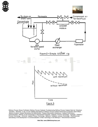
![A different membrane material may be less prone to fouling. Altering
operating conditions can also reduce fouling. A reduction in operating
temperature or pressure will reduce Initial flux but overall flux with time
may be improved if fouling is inhibited.
Alternatively, when an uneconomic flux is reached the process can be
stopped and the membranes cleaned. Chemical cleaning is usually the
most effective but larger bore membrane tubes can be cleaned physically
in situ. A recent BIOSEP SAR report deals exclusively with the cleaning of
membranes [8].
In addition to reducing flux fouling may have a secondary effect as the
fouling layer can become the separating medium. Solutes or particles
which pass freely through the membrane may be partially or even totally
rejected by the fouling layer, thus changing the separation.
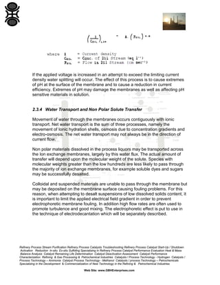
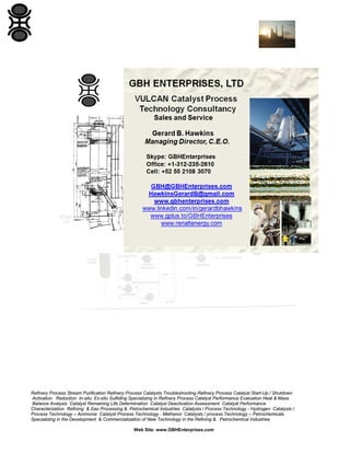
Polarization occurs when molecules/particles rejected by the membrane
concentrate at the membrane surface. Crossflow will minimize this
concentration but will never entirely eliminate it. Most polarization studies
have investigated the concentration of solutes at the membrane surface.
The solute concentration at the membrane surface quickly increases to a
maximum value when the solute precipitates or forms a thixotropic gel.
Gel formation is analogous to cake formation in conventional filtration. The
gel concentration will depend upon chemical and morphological properties
of the solute and may vary from 10 to 75%. Flux, J, under conditions of gel
polarization is described by the widely accepted Blatt [2] equation:
where Cg and Cb are the suspended solid concentrations in the gel and
the bulk respectively; ks is an empirical constant considered later.
With particulates diffusive back-transport may not be significant and
equation (1) will not apply. Constant pressure particulate filtration without
back-transport can sometimes be described by the well-known cake
filtration equation:
Refinery Process Stream Purification Refinery Process Catalysts Troubleshooting Refinery Process Catalyst Start-Up / Shutdown
Activation Reduction In-situ Ex-situ Sulfiding Specializing in Refinery Process Catalyst Performance Evaluation Heat & Mass
Balance Analysis Catalyst Remaining Life Determination Catalyst Deactivation Assessment Catalyst Performance
Characterization Refining & Gas Processing & Petrochemical Industries Catalysts / Process Technology - Hydrogen Catalysts /
Process Technology – Ammonia Catalyst Process Technology - Methanol Catalysts / process Technology – Petrochemicals
Specializing in the Development & Commercialization of New Technology in the Refining & Petrochemical Industries
Web Site: www.GBHEnterprises.com](https://image.slidesharecdn.com/otherseparationstechniquesforsuspensions-140114183415-phpapp01/85/Other-Separations-Techniques-for-Suspensions-8-320.jpg)
![(The derivation and interpretation of this equation is reviewed in Section
1.5.2(b)).
Schneider [3] suggests that initial flux decline in CMF can be described by
equation (2). However, as equation (2) infers that all particles convected to
the polarized layer are accumulated it is unlikely to apply in the crossflow
situation.
The Scour Model [4] is based on the analogy between suspension flow
across a filter cake and the motion of a sediment laden stream over a
layer settled sediment. For the UF/CMF of suspensions of the Scour
Model equates convective deposition and scour removal giving:
Although none of the above equations are entirely satisfactory they are
useful in relating flux to other parameters.
1.4.2 Pressure
Flux in UF and CMF can be described by a resistance in series
relationship:
where Rm and Rp are the medium and polarization resistance terms.
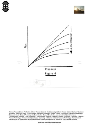
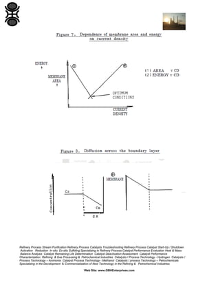
Pure water flux is proportional to pressure. With suspensions, increasing
pressure (and flux) tend to increase the polarized layer and hence
resistance. It is possible to reach a limiting flux where further increases in
pressure are matched by increases in Rp (see Figure 4). This is
analogous to the effects of solids compressibility during cake filtration on
the pressure-dependence of filtration rate (Section 3.5).
Many users advise running at low pressures as this has the added
advantage of avoiding fouling due to compaction of the polarized layer.
Refinery Process Stream Purification Refinery Process Catalysts Troubleshooting Refinery Process Catalyst Start-Up / Shutdown
Activation Reduction In-situ Ex-situ Sulfiding Specializing in Refinery Process Catalyst Performance Evaluation Heat & Mass
Balance Analysis Catalyst Remaining Life Determination Catalyst Deactivation Assessment Catalyst Performance
Characterization Refining & Gas Processing & Petrochemical Industries Catalysts / Process Technology - Hydrogen Catalysts /
Process Technology – Ammonia Catalyst Process Technology - Methanol Catalysts / process Technology – Petrochemicals
Specializing in the Development & Commercialization of New Technology in the Refining & Petrochemical Industries
Web Site: www.GBHEnterprises.com](https://image.slidesharecdn.com/otherseparationstechniquesforsuspensions-140114183415-phpapp01/85/Other-Separations-Techniques-for-Suspensions-9-320.jpg)
![1.4.3 Crossflow
In general, flux can be increased by increasing crossflow velocity. The
Scour Model, equation (3), relates flux and crossflow. With bacterial
suspensions , Fane [4] showed that Initial flux was proportional to U’-0, as
expected. However, long term steady state flux was found to be
proportional to U2.4, This demonstrates the beneficial effect increased
crossflow velocity can have in reducing fouling rate.
1.4.4 Temperature
Flux through porous media can be described by Poiseuille’s Law:
(where the symbols are as defined in Section 1.5.2(b) (I)).
In UF/CMF flux has been shown experimentally to be inversely
proportional to permeate viscosity as predicted by this equation. For
aqueous suspensions increasing temperature will therefore Increase flux.
If increasing temperature also reduces suspension viscosity pumping
costs will be reduced.
In practice it may or may not be economic to heat the suspension but it is
certainly sensible to avoid cooling unless the suspension is thermally
unstable.
1.4.5 Concentration
Equation (1) predicts that flux is proportional to the log of concentration.
This is the generally accepted relationship and has been verified for a
number of suspensions [5].
Equation (3), however, which is probably more general for suspensions,
predicts a log/log relationship between flux and concentration. This has
also been demonstrated experimentally for a number of suspensions
[4].
Refinery Process Stream Purification Refinery Process Catalysts Troubleshooting Refinery Process Catalyst Start-Up / Shutdown
Activation Reduction In-situ Ex-situ Sulfiding Specializing in Refinery Process Catalyst Performance Evaluation Heat & Mass
Balance Analysis Catalyst Remaining Life Determination Catalyst Deactivation Assessment Catalyst Performance
Characterization Refining & Gas Processing & Petrochemical Industries Catalysts / Process Technology - Hydrogen Catalysts /
Process Technology – Ammonia Catalyst Process Technology - Methanol Catalysts / process Technology – Petrochemicals
Specializing in the Development & Commercialization of New Technology in the Refining & Petrochemical Industries
Web Site: www.GBHEnterprises.com](https://image.slidesharecdn.com/otherseparationstechniquesforsuspensions-140114183415-phpapp01/85/Other-Separations-Techniques-for-Suspensions-10-320.jpg)
![This predicts that flux decreases as particle size increases.
Fane [6] showed experimentally that as particle size increased from 0.025
micron to 20 micron UF flux passes through a minimum as polarization
control changed from diffusive (decreasing with particle size) to nondiffusive (increasing with particle size). The minima occurred at about 0.1
micron.
Particle size range and shape are also obviously important in determining
polarized layer permeability and flux. Their effect awaits investigation.
1.4.8 Particle Charge
Using monodisperse silica colloids of different zeta potentials, McDonogh
[7] has shown that particle charge has a substantial effect on the
permeability of polarized layers. An increase in zeta potential leads to a
decrease in specific cake resistance (presumably by increasing cake
porosity - see equation (7)). The theory developed breaks down at low
zeta potentials (< 5 mV) where particles in the concentrated zone near the
membrane are highly likely to flocculate before laydown leading to larger
deposited particles and higher fluxes.
1.4.9 Other Factors
Hany other parameters relating to suspensions, membranes and operating
conditions can influence flux and require further investigation. For
example, Fane [4] has shown that particle rigidity and the presence of
macrosolutes are important. Charged membranes have shown some
promise in reducing fouling. Unfortunately, a full understanding of the
important parameters and the ability to predict and optimize flux are still a
long way off.
Refinery Process Stream Purification Refinery Process Catalysts Troubleshooting Refinery Process Catalyst Start-Up / Shutdown
Activation Reduction In-situ Ex-situ Sulfiding Specializing in Refinery Process Catalyst Performance Evaluation Heat & Mass
Balance Analysis Catalyst Remaining Life Determination Catalyst Deactivation Assessment Catalyst Performance
Characterization Refining & Gas Processing & Petrochemical Industries Catalysts / Process Technology - Hydrogen Catalysts /
Process Technology – Ammonia Catalyst Process Technology - Methanol Catalysts / process Technology – Petrochemicals
Specializing in the Development & Commercialization of New Technology in the Refining & Petrochemical Industries
Web Site: www.GBHEnterprises.com](https://image.slidesharecdn.com/otherseparationstechniquesforsuspensions-140114183415-phpapp01/85/Other-Separations-Techniques-for-Suspensions-12-320.jpg)
![For the future membrane separation is a fast developing area and significant
improvements can be expected in the next few years.
The biggest problem to be overcome is membrane fouling. This is a particular
problem in the biochemical area which offers membrane separation its largest
potential market. A membrane with greatly reduced susceptibility to fouling by
proteins is available but only for small laboratory-scale units. Further
developments in the area of antifouling membranes are anticipated. Relevant
research in this area has already been reviewed in Section 1.5 (see references
[39-44]1 of that section).
Little effort has been directed towards the optimization of module geometry in
terms of energy efficiency. Work is now in progress in this area but optimum
design may turn out to be highly feed dependent.
Membrane manufacturers will probably introduce membranes with greater
chemical resistance, higher fluxes and sharper cut-offs. This should allow UF and
CMF to be used in a wider range of applications.
1.6
SUMMARY OF SYMBOLS USED
A
Cb
Cg
D
dP
ds
J
Kb
Ke
Ks
l
n
N
N
ΔP
Rm
Rp
T
t
U
membrane area
bulk concentration
gel concentration
diffusion coefficient
pore diameter (average)
particle diameter
flux
Boltzmann's constant
Scour coefficient
mass transfer coefficient
pore length (including tortuosity factor)
mass of polarized solids
number of pores per unit area
layer thickness
pressure drop across membrane
membrane resistance
polarized layer resistance
absolute temperature
time
crossflow velocity
Refinery Process Stream Purification Refinery Process Catalysts Troubleshooting Refinery Process Catalyst Start-Up / Shutdown
Activation Reduction In-situ Ex-situ Sulfiding Specializing in Refinery Process Catalyst Performance Evaluation Heat & Mass
Balance Analysis Catalyst Remaining Life Determination Catalyst Deactivation Assessment Catalyst Performance
Characterization Refining & Gas Processing & Petrochemical Industries Catalysts / Process Technology - Hydrogen Catalysts /
Process Technology – Ammonia Catalyst Process Technology - Methanol Catalysts / process Technology – Petrochemicals
Specializing in the Development & Commercialization of New Technology in the Refining & Petrochemical Industries
Web Site: www.GBHEnterprises.com](https://image.slidesharecdn.com/otherseparationstechniquesforsuspensions-140114183415-phpapp01/85/Other-Separations-Techniques-for-Suspensions-14-320.jpg)
![V
a
ƹ
n
ρ
2
volume of permeate
specific cake resistance
porosity
viscosity of permeate
density
ELECTRODIALYSIS
2.1
INTRODUCTION
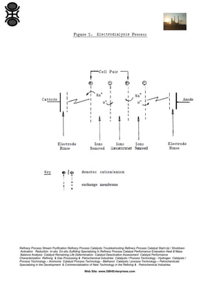
Under the influence of an electric field Ions in solution move towards the
electrodes where electrolysis takes place. If, however, membranes permeable
only to cations or anions are placed as barriers in the path of the migrating ions,
such that a series of compartments are formed, then it is possible to trap
electrolyte in some compartments whilst removing it from adjacent compartments
(see Figure 5).
This technique is termed electrodialysis (ED) [9] and was originally developed by
the water treatment industry as a means of purifying brackish supplies. In recent
years ED has been used in the food industry (whey processing), in recovery of
metals from electroplating solutions and in the de-ashing of pharmaceuticals.
Hence chemical processing by electrodialysis involves removing dissolved salts
from slurries or suspensions or from dissolved neutral molecules. The GBHE
Engineering Group has studied the application of ED to problems ranging from
the de-ashlng of catalyst slurries through biological and pharmaceutical materials
to the desalting of dyes. One of the essential criteria for such applications is that
the liquor to be treated should be capable of being pumped through the channels
of the ED stack without causing blockages. This requirement obviously
constrains the viscosity range of the fluid as well as limiting particle size, colloidal
stability and sedimentation characteristics.
Refinery Process Stream Purification Refinery Process Catalysts Troubleshooting Refinery Process Catalyst Start-Up / Shutdown
Activation Reduction In-situ Ex-situ Sulfiding Specializing in Refinery Process Catalyst Performance Evaluation Heat & Mass
Balance Analysis Catalyst Remaining Life Determination Catalyst Deactivation Assessment Catalyst Performance
Characterization Refining & Gas Processing & Petrochemical Industries Catalysts / Process Technology - Hydrogen Catalysts /
Process Technology – Ammonia Catalyst Process Technology - Methanol Catalysts / process Technology – Petrochemicals
Specializing in the Development & Commercialization of New Technology in the Refining & Petrochemical Industries
Web Site: www.GBHEnterprises.com](https://image.slidesharecdn.com/otherseparationstechniquesforsuspensions-140114183415-phpapp01/85/Other-Separations-Techniques-for-Suspensions-15-320.jpg)
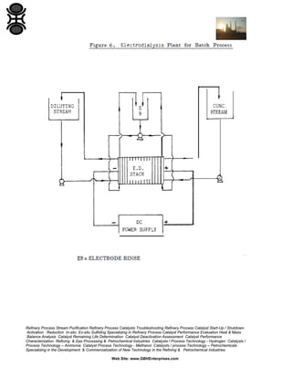
![2.4 EXAMPLES
Two applications of electrodialysis in current GBHE process technology are of
interest. An electrodialysis operation was being employed to remove calcium ions
(and traces of HCl) from glucose solution in the Cellulose Hydrolysis
development project of a European Conglomerate. In addition the technique has
been used to desalt dyestuff suspensions [11]. Further details may be found in
the references.
3
ELECTRODEWATERING AND ELECTRODECANTATION
3.1
INTRODUCTION
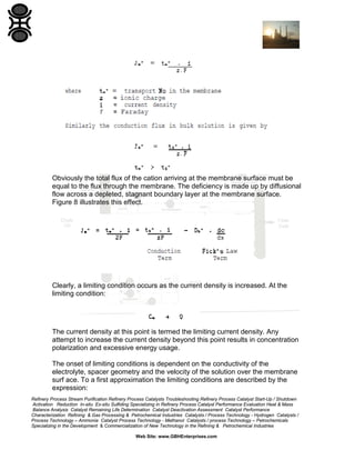
Both techniques are practical manifestations of the application of electrophoresis
to large scale concentration of sols or suspensions. The two techniques differ
mainly in the configuration of the engineering that effects the electrophoreticallydriven separation. GBHE uses electrodecantation to concentrate PTFE
suspensions while the IEEE has expertise in application of these techniques to a
wide range of separation problems including the concentration of protein and
cellular material.
The main pre-requisite for these methods is a solution of low ionic strength
(typically < low-3 m).
3.2
PRINCIPLES AND OPERATION
An electrodecantation unit (see Figures 1 and 2 of Reference [12]) is basically a
tank with electrodes at either end or a large number of membranes interposed
between and parallel to the electrodes. When the unit is filled with a suspension
and the electric field is applied, charged particles move towards their opposite
poles. When the particles reach a membrane (the membrane acts as a physical
barrier to particles but conducts electricity) they pile up forming a dense layer
which then sediments. At a partner membrane particles are repelled forming a
less dense layer which gravitates to the surface. A flow pattern is established in a
membrane channel analogous to convection current. Thus a dense phase is
formed at the bottom of the unit and clear water at the top.
Both layers are drawn off and the cell volume is maintained by adding
suspension at the vertical midpoint of the tank.
Refinery Process Stream Purification Refinery Process Catalysts Troubleshooting Refinery Process Catalyst Start-Up / Shutdown
Activation Reduction In-situ Ex-situ Sulfiding Specializing in Refinery Process Catalyst Performance Evaluation Heat & Mass
Balance Analysis Catalyst Remaining Life Determination Catalyst Deactivation Assessment Catalyst Performance
Characterization Refining & Gas Processing & Petrochemical Industries Catalysts / Process Technology - Hydrogen Catalysts /
Process Technology – Ammonia Catalyst Process Technology - Methanol Catalysts / process Technology – Petrochemicals
Specializing in the Development & Commercialization of New Technology in the Refining & Petrochemical Industries
Web Site: www.GBHEnterprises.com](https://image.slidesharecdn.com/otherseparationstechniquesforsuspensions-140114183415-phpapp01/85/Other-Separations-Techniques-for-Suspensions-22-320.jpg)
![Other variations of the technique use moving membranes from which the
deposited material is removed with a doctor blade, or collecting laminae from a
stream flowing between electrodes.
3.3
EQUIPMENT AND OPERATING PARAMETERS
Electrodecantation typically uses GRP or similar tanks of 1-2 m3 capacity. The
membrane is generally cellulose acetate dialysis type sheet placed in the tank in
sheets, held apart by non-conductive rods. The electrodes may be any of the well
known coated types now available.
The range of final solids concentrations that can be handled is very much
controlled by the rheological properties of the slurry and may range from a few
percent for clay up to 60 or 70% for polymer latex.
Typical electrical field strengths lie in the region of 1 to 5 volts cm-1 while the
current density ranges from 1 to 10 mA cm-2.
3.4
EXAMPLES
Electrodewatering using the Dorr-Oliver Electrically-Assisted Vacuum Filtration
(EAVF) rig is currently being employed for PVC latex thickening on a Pilot Scale
at European Company [12]. It has also been considered as an isolation method
for certain fluoropolymer latex suspensions. This latter example illustrates an
important suspension processing strategy. EAVF is a valuable separation
technique for stable, colloidal suspensions where flocculation via addition of
surfactants, flocculants or salts is to be avoided. Thus polymer latex suspensions
whose intended use is for insulating materials are well dewatered by this means.
4 MAGNETIC SEPARATION METHODS
It has not proved possible to provide a contribution on the application of magnetic
methods of solid/liquid separation at this time. Since many of the potential outlets
for such methods are in Biotechnology, a useful introduction to the subject may
be found in the reference [13].
Refinery Process Stream Purification Refinery Process Catalysts Troubleshooting Refinery Process Catalyst Start-Up / Shutdown
Activation Reduction In-situ Ex-situ Sulfiding Specializing in Refinery Process Catalyst Performance Evaluation Heat & Mass
Balance Analysis Catalyst Remaining Life Determination Catalyst Deactivation Assessment Catalyst Performance
Characterization Refining & Gas Processing & Petrochemical Industries Catalysts / Process Technology - Hydrogen Catalysts /
Process Technology – Ammonia Catalyst Process Technology - Methanol Catalysts / process Technology – Petrochemicals
Specializing in the Development & Commercialization of New Technology in the Refining & Petrochemical Industries
Web Site: www.GBHEnterprises.com](https://image.slidesharecdn.com/otherseparationstechniquesforsuspensions-140114183415-phpapp01/85/Other-Separations-Techniques-for-Suspensions-23-320.jpg)

The document serves as a processing guide for suspensions in the refining and petrochemical industries, detailing various separation techniques, primarily focusing on pressure-driven membrane processes such as ultrafiltration and crossflow microfiltration. It highlights key operating parameters, membrane structures, and factors affecting performance, including polarization, fouling, and pressure, while providing a comprehensive framework for evaluating and optimizing the use of membranes in industrial applications. Additionally, it emphasizes the importance of understanding the characteristics of both the suspensions and the membranes to achieve efficient separation outcomes.


![Capital Projects Assessment [Infographic]](https://cdn.slidesharecdn.com/ss_thumbnails/capitalprojectsassessment-130814143908-phpapp01-thumbnail.jpg?width=640&height=640&fit=bounds)


