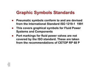
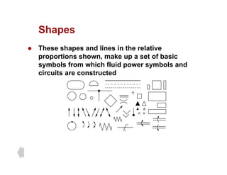
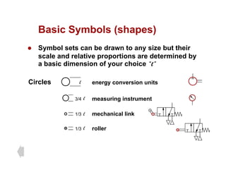
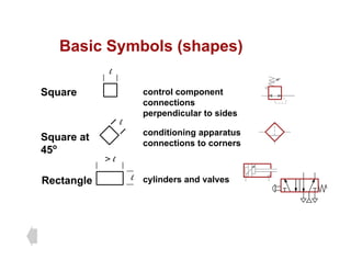
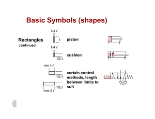
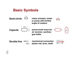
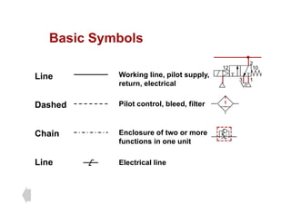
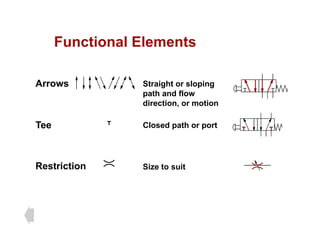
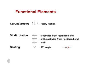
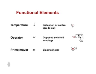
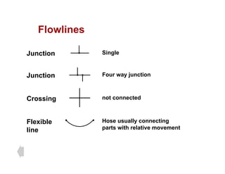
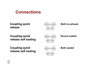
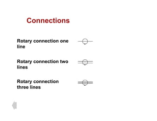
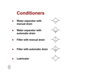
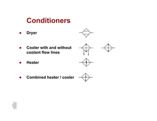
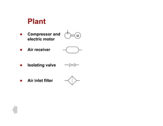
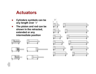
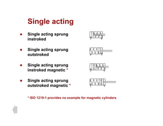
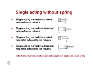
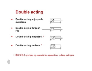
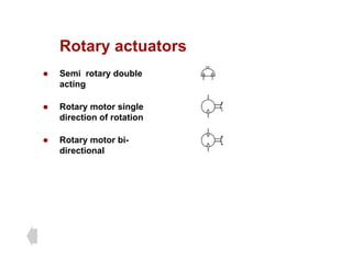
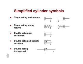
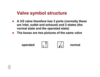
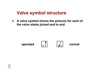
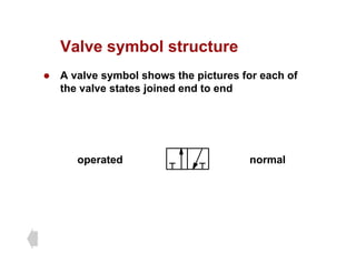
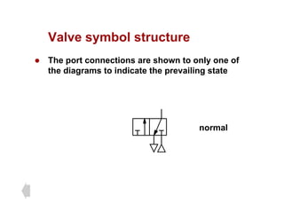
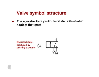
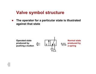
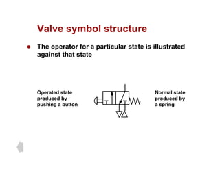
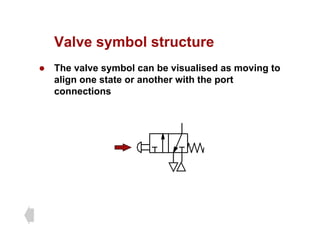
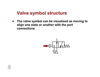
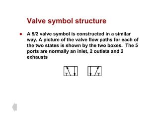
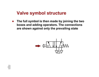
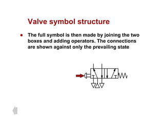
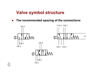
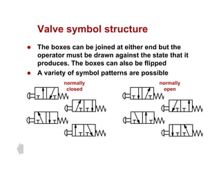
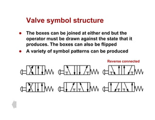
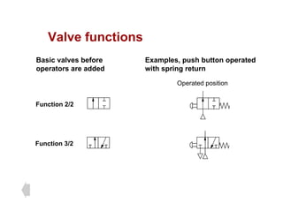
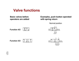
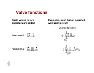
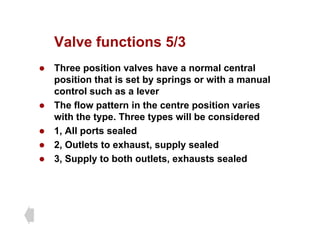
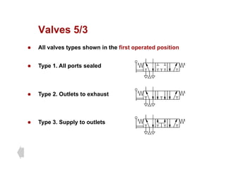
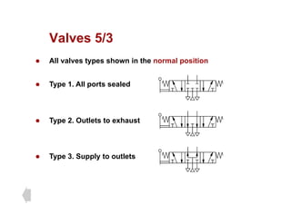
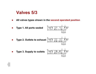
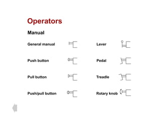
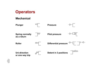
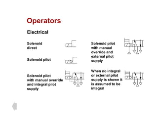
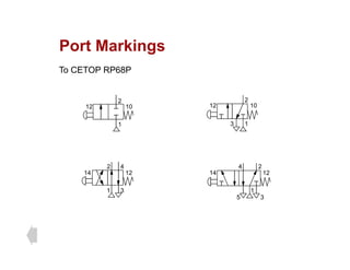
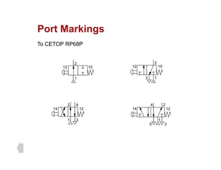
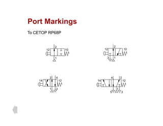
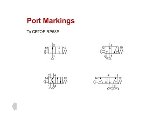
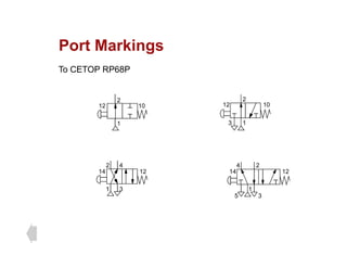
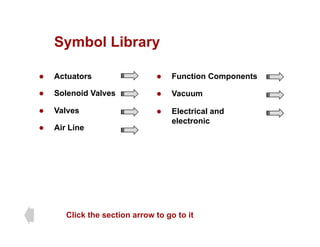
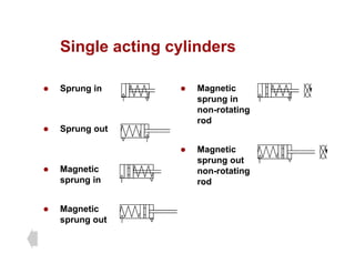
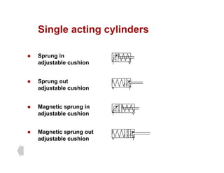
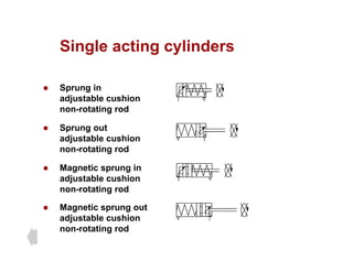
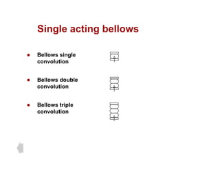
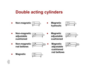
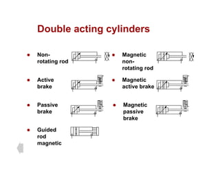
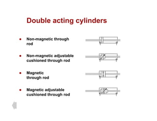
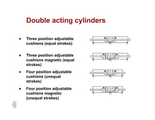
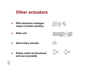
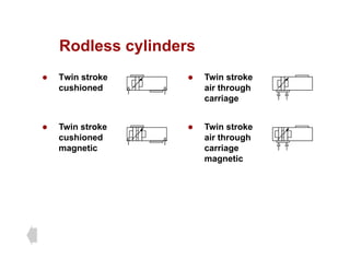
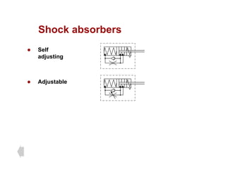
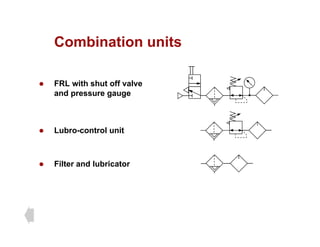
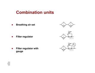
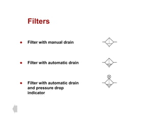
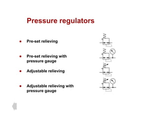
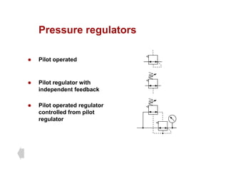
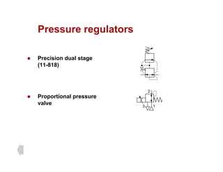
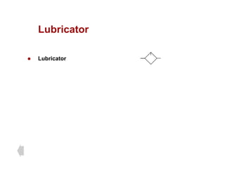
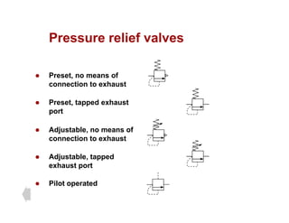
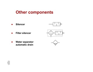
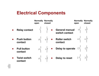
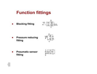
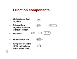
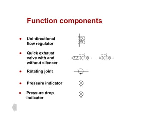
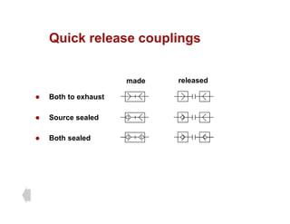
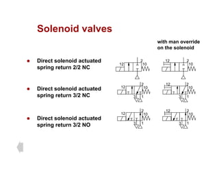
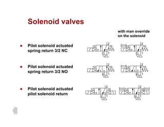
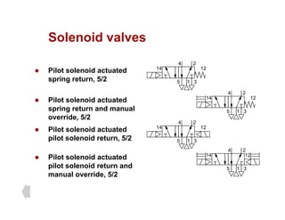
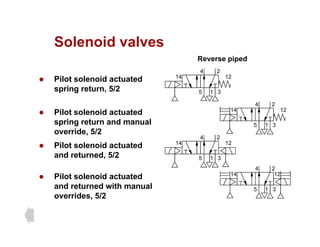
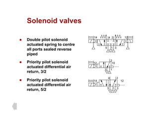
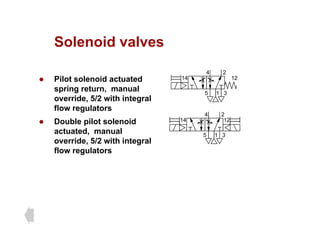
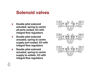
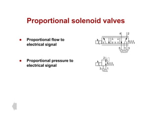
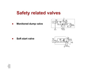
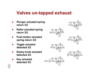
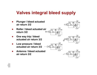
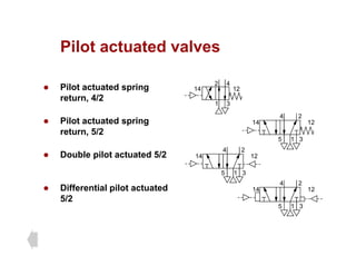
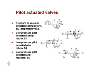
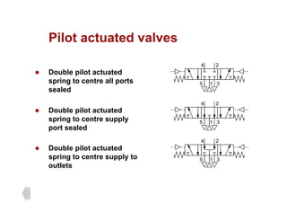
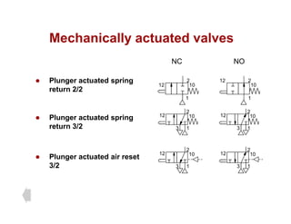
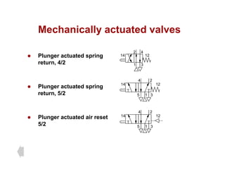
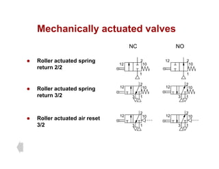
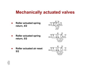
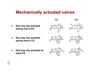
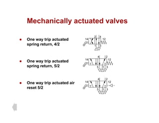
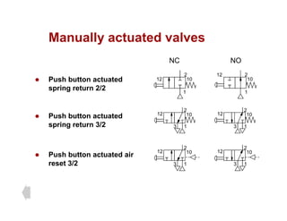
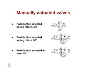
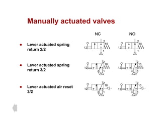
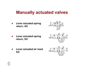
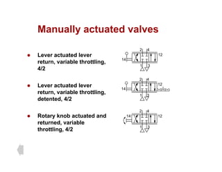
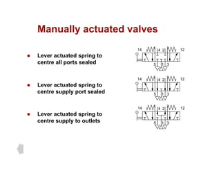
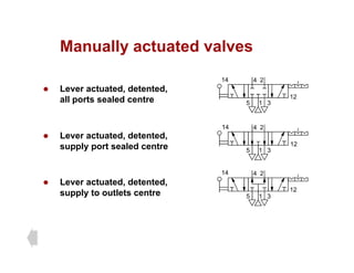
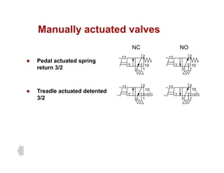
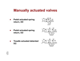
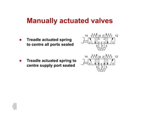
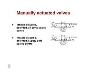
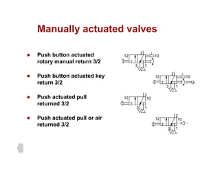
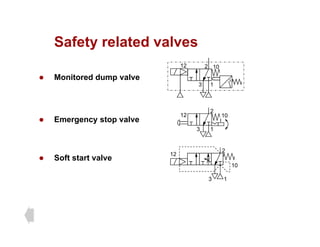
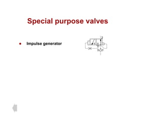
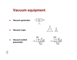
Pneumatic Symbols
Pneumatic Symbols
For system diagrams and component
identification
Contents
Contents
z Standards z Actuators
B i b l V l b l t t
z Basic symbols
z Functional elements
z Flowlines
z Valve symbol structure
z Valve functions
z Three position valves
z Connections
z Conditioners and plant
z Pressure regulators
z Operators
z Port marking
z Function components
z Pressure regulators
z Relief valves
z Function components
z Symbol Library
Click the section to advance directly to it
Graphic Symbols Standards
z Pneumatic symbols conform to and are devised
f th I t ti l St d d ISO 1219 1 1991
from the International Standard ISO 1219-1 1991
z This covers graphical symbols for Fluid Power
Systems and Components
z Port markings for fluid power valves are not
covered by the ISO standard. These are taken
f th d ti f CETOP RP 68 P
from the recommendations of CETOP RP 68 P
CETOP
CETOP
z Who is CETOP? CETOP is the abbreviation of Comité Européen des
Transmissions Oléohydrauliques et Pneumatiques. CETOP is the
y q q
European Fluid Power Committee.
Thus, it is:
z · The communication platform for fluid power in Europe.
· The international umbrella organisation for national fluid power
The international umbrella organisation for national fluid power
associations in Europe.
z Through the 18 national associations which are member of CETOP, all
well known companies in Europe belong to the European Committee.
Many of these companies are leading fluid power manufacturers and
major players in the international markets.
z CETOP represents more than 1,000 companies - mainly manufacturers,
but also some dealers - with almost 70,000 employees and a market value
of abo t 13 billion EURO These acco nt for a er high proportion of
of about 13 billion EURO. These account for a very high proportion of
companies active in these fields - 80-90% in most countries.
Basic Symbols
Shapes
Shapes
z These shapes and lines in the relative
ti h k t f b i
proportions shown, make up a set of basic
symbols from which fluid power symbols and
circuits are constructed
Basic Symbols (shapes)
z Symbol sets can be drawn to any size but their
l d l ti ti d t i d b
scale and relative proportions are determined by
a basic dimension of your choice “l”
Circles l energy conversion units
l
3/4 measuring instrument
l
3/4 measuring instrument
l
1/3 mechanical link
l
1/3 roller
Basic Symbols (shapes)
l
Square control component
connections
perpendicular to sides
Square at
45o
conditioning apparatus
connections to corners
l
45
Rectangle cylinders and valves
l
> l
Basic Symbols (shapes)
1/4 l
Rectangles
continued
piston
l
1/4 l
cushion
min 1 l
1/2 l
certain control
methods, length
between limits to
1/2 l
between limits to
suit
max 2 l
1/2 l
Basic Symbols
Basic Symbols
rotary actuator motor
Semi circle
l
rotary actuator, motor
or pump with limited
angle of rotation
Semi-circle
Capsule pressurised reservoir
air receiver, auxiliary
b ttl
2 l
l
mechanical connection
Double line
gas bottle
mechanical connection
piston rod, lever, shaft
Double line
1/5 l
Basic Symbols
Basic Symbols
2
12 10
Line Working line, pilot supply,
return, electrical
1
3
Dashed Pilot control, bleed, filter
Chain Enclosure of two or more
functions in one unit
Line Electrical line
Functional Elements
Functional Elements
Functional Elements
1/4 l
1/2 l
Triangle Direction and nature of fluid,
open pneumatic or filled
hydraulic
size to suit
Spring
Long sloping indicates
Arrow 1/3 l
g p g
adjustability
1/3 l
Functional Elements
Functional Elements
Straight or sloping
path and flow
direction, or motion
Arrows
Tee Closed path or port
Size to suit
Restriction
Functional Elements
Functional Elements
rotary motion
Curved arrows
clockwise from right hand end
Shaft rotation
anti-clockwise from right hand end
90o
angle
Seating
anti-clockwise from right hand end
both
g
g
Functional Elements
Functional Elements
Indication or control
size to suit
Temperature
Operator Opposed solenoid
windings
g
Prime mover M
M
Electric motor
Flowlines and Connections
Flowlines
Flowlines
Junction Single
Junction Single
Junction Four way junction
not connected
Crossing
Junction Four way junction
not connected
Crossing
Hose usually connecting
Fl ibl Hose usually connecting
parts with relative movement
Flexible
line
Connections
Connections
Continuous
Air bleed
Temporary by probe
Air exhaust No means of
connection
With means of
connection
Connections
Connections
Both to exhaust
Coupling quick
release
Coupling quick
release self sealing
Source sealed
release self sealing
Coupling quick Both sealed
p g q
release self sealing
Connections
Connections
Rotary connection one
line
Rotary connection two
lines
lines
Rotary connection
y
three lines
Conditioners and Pressure
Producing Plant
Conditioners
Conditioners
z Water separator with
manual drain
manual drain
z Water separator with
automatic drain
automatic drain
z Filter with manual drain
z Filter with automatic drain
z Lubricator
Conditioners
Conditioners
z Dryer
z Cooler with and without
coolant flow lines
coolant flow lines
z Heater
z Combined heater / cooler
Plant
Plant
z Compressor and
electric motor
M
electric motor
z Air receiver
z Isolating valve
z Air inlet filter
Pressure Control
Pressure regulators
Pressure regulators
z A pressure regulator symbol represents a normal state with
the spring holding the regulator valve open to connect the
supply to the outlet.
z The dotted line represents the feedback, this opposes the
spring and can vary the flow through the valve from full
flow, through shut off, to exhaust. The symbol is usually
drawn in only this one state. The flow path can be imagined
to hinge at the right hand end to first shut off the supply
g g pp y
then connect to the exhaust.
z Adjustable Regulator
z Adjustable Regulator with
pressure gauge simplified
simplified
p g g p
Filter Regulator Lubricator
z FRL Combined unit
z FRL Simplified symbol
Pressure relief valves
z A pressure relief valve symbol represents a normal state
with the spring holding the valve closed
with the spring holding the valve closed.
z The dotted line represents feed-forward, this opposes the
spring and can be imagined to lift the flow path When the
spring and can be imagined to lift the flow path. When the
pressure reaches an excess value the flow path will line up
with the ports and flow air to relief.
z Adjustable relief valve
simplified
simplified
z Preset relief valve
simplified
p
Actuators
Actuators
Actuators
z Cylinders symbols can be
any length over “l”
“l”
any length over l
z The piston and rod can be
shown in the retracted,
extended or any
extended or any
intermediate position
Single acting
Single acting
z Single acting sprung
instroked
instroked
z Single acting sprung
outstroked
outstroked
z Single acting sprung
instroked magnetic *
instroked magnetic
z Single acting sprung
outstroked magnetic *
outstroked magnetic
* ISO 1219-1 provides no example for magnetic cylinders
Single acting without spring
z Single acting normally instroked
external force returns
z Single acting normally outstroked
external force returns
z Single acting normally instroked
magnetic external force returns
z Single acting normally outstroked
magnetic external force returns
Note: the hardware is usually double acting cylinders applied as single acting
Double acting
Double acting
z Double acting adjustable
cushions
cushions
z Double acting through
rod
rod
z Double acting magnetic *
z Double acting rodless *
* ISO 1219-1 provides no example for magnetic or rodless cylinders
Rotary actuators
Rotary actuators
z Semi rotary double
acting
acting
z Rotary motor single
direction of rotation
z Rotary motor bi-
directional
directional
Simplified cylinder symbols
z Single acting load returns
z Single acting spring
returns
returns
z Double acting non
cushioned
cushioned
z Double acting adjustable
cushions
cushions
z Double acting
through rod
g
Valve symbol structure
z The function of a valve is given by a pair of
l t d b t k 3/2
numerals separated by a stroke, e.g. 3/2..
z The first numeral indicates the number of main
ports. These are inlets, outlets and exhausts but
excludes signal ports and external pilot feeds.
z The second numeral indicates the number of
t t th l hi
states the valve can achieve.
Valve symbol structure
z A 3/2 valve therefore has 3 ports (normally these
i l t tl t d h t) d 2 t t (th
are inlet, outlet and exhaust) and 2 states (the
normal state and the operated state)
z The boxes are two pictures of the same valve
normal
operated
Valve symbol structure
z A valve symbol shows the pictures for each of
th l t t j i d d t d
the valve states joined end to end
normal
operated
Valve symbol structure
z A valve symbol shows the pictures for each of
th l t t j i d d t d
the valve states joined end to end
normal
operated
Valve symbol structure
z The port connections are shown to only one of
th di t i di t th ili t t
the diagrams to indicate the prevailing state
normal
Valve symbol structure
z The operator for a particular state is illustrated
i t th t t t
against that state
Operated state
p
produced by
pushing a button
Valve symbol structure
z The operator for a particular state is illustrated
i t th t t t
against that state
Operated state Normal state
p
produced by
pushing a button
produced by
a spring
Valve symbol structure
z The operator for a particular state is illustrated
i t th t t t
against that state
Operated state Normal state
p
produced by
pushing a button
produced by
a spring
Valve symbol structure
z The valve symbol can be visualised as moving to
li t t th ith th t
align one state or another with the port
connections
Valve symbol structure
z The valve symbol can be visualised as moving to
li t t th ith th t
align one state or another with the port
connections
Valve symbol structure
z The valve symbol can be visualised as moving to
li t t th ith th t
align one state or another with the port
connections
Valve symbol structure
z A 5/2 valve symbol is constructed in a similar
A i t f th l fl th f h f
way. A picture of the valve flow paths for each of
the two states is shown by the two boxes. The 5
ports are normally an inlet, 2 outlets and 2
p y
exhausts
Valve symbol structure
z The full symbol is then made by joining the two
b d ddi t Th ti
boxes and adding operators. The connections
are shown against only the prevailing state
Valve symbol structure
z The full symbol is then made by joining the two
b d ddi t Th ti
boxes and adding operators. The connections
are shown against only the prevailing state
Valve symbol structure
z The full symbol is then made by joining the two
b d ddi t Th ti
boxes and adding operators. The connections
are shown against only the prevailing state
Valve symbol structure
z The recommended spacing of the connections
1/4 l 1 /4 l 1/4 l
1 l
1/4 l
1/2 l
1/2 l 1/2 l
1/4 l
1/2 l
1/4 l
1/2 l
Valve symbol structure
z The boxes can be joined at either end but the
t t b d i t th t t th t it
operator must be drawn against the state that it
produces. The boxes can also be flipped
z A variety of symbol patterns are possible
normally
closed
normally
open
Valve symbol structure
z The boxes can be joined at either end but the
t t b d i t th t t th t it
operator must be drawn against the state that it
produces. The boxes can also be flipped
z A variety of symbol patterns can be produced
Reverse connected
Valve functions
Valve functions
Valve functions
Basic valves before
operators are added
Examples, push button operated
with spring return
Normal position
operators are added with spring return
Function 2/2
Function 3/2
Valve functions
Valve functions
Basic valves before
operators are added
Examples, push button operated
with spring return
Operated position
operators are added with spring return
Function 2/2
Function 3/2
Valve functions
Valve functions
Basic valves before
operators are added
Examples, push button operated
with spring return
Normal position
operators are added with spring return
Function 4/2
Function 5/2
Valve functions
Valve functions
Basic valves before
operators are added
Examples, push button operated
with spring return
Operated position
operators are added with spring return
Function 4/2
Function 5/2
Valve functions 5/3
Valve functions 5/3
z Three position valves have a normal central
iti th t i t b i ith l
position that is set by springs or with a manual
control such as a lever
z The flow pattern in the centre position varies
with the type. Three types will be considered
z 1, All ports sealed
z 2, Outlets to exhaust, supply sealed
z 3, Supply to both outlets, exhausts sealed
Valves 5/3
Valves 5/3
z All valves types shown in the normal position
z Type 1. All ports sealed
z Type 2. Outlets to exhaust
T 3 S l t tl t
z Type 3. Supply to outlets
Valves 5/3
Valves 5/3
z All valves types shown in the first operated position
z Type 1. All ports sealed
z Type 2. Outlets to exhaust
T 3 S l t tl t
z Type 3. Supply to outlets
Valves 5/3
Valves 5/3
z All valves types shown in the normal position
z Type 1. All ports sealed
z Type 2. Outlets to exhaust
T 3 S l t tl t
z Type 3. Supply to outlets
Valves 5/3
Valves 5/3
z All valves types shown in the second operated position
z Type 1. All ports sealed
z Type 2. Outlets to exhaust
T 3 S l t tl t
z Type 3. Supply to outlets
Valves 5/3
Valves 5/3
z All valves types shown in the normal position
z Type 1. All ports sealed
z Type 2. Outlets to exhaust
T 3 S l t tl t
z Type 3. Supply to outlets
Operators
Operators
Operators
Manual
General manual Lever
Push button Pedal
Pull button Treadle
Push/pull button Rotary knob
Operators
Operators
Mechanical
Plunger Pressure
Spring normally
as a return
Pilot pressure
Roller Differential pressure
Uni-direction
or one way trip
Detent in 3 positions
Operators
Operators
Electrical
Solenoid
direct
Solenoid pilot
with manual
override and
Solenoid pilot
override and
external pilot
supply
Solenoid pilot
with manual override
and integral pilot
When no integral
or external pilot
supply is shown it
is assumed to be
and integral pilot
supply
is assumed to be
integral
Port markings
Port Markings
Port Markings
To CETOP RP68P
2
12 10
2
12 10
1 1
3
2
4
14 12
2 4
14 12
1
5 3
1 3
Port Markings
Port Markings
To CETOP RP68P
2
12 10
2
12 10
1 1
3
2
4
14 12
2 4
14 12
1
5 3
1 3
Port Markings
Port Markings
To CETOP RP68P
2
12 10
2
12 10
1 1
3
2
4
14 12
2 4
14 12
1
5 3
1 3
Port Markings
Port Markings
To CETOP RP68P
2
12 10
2
12 10
1 1
3
2
4
14 12
2 4
14 12
1
5 3
1 3
Port Markings
Port Markings
To CETOP RP68P
2
12 10
2
12 10
1 1
3
2
4
14 12
2 4
14 12
1
5 3
1 3
Function components
Function components
Function components
z Non-return valve
simplified
simplified
z Flow regulator uni-
directional
directional
z Flow regulator bi-
directional simplified
Note: The output can exhaust
back and is not trapped
z Two pressure ‘AND’
simplified
simplified
z Shuttle valve ‘OR’
simplified
p
Function components
Function components
z Quick exhaust valve with
silencer simplified
silencer simplified
z Silencer
z Pressure to electric
switch preset
switch preset
z Pressure to electric
switch adjustable
switch adjustable
Symbol Library
Symbol Library
z Actuators z Function Components
z Actuators
z Solenoid Valves
V l
z Function Components
z Vacuum
z Valves
z Air Line
z Electrical and
electronic
Click the section arrow to go to it
Symbol Library
Symbol Library
Actuators
Single acting cylinders
S i M ti
z Sprung in z Magnetic
sprung in
non-rotating
rod
z Sprung out
rod
z Magnetic
z Magnetic
sprung in
g
sprung out
non-rotating
rod
z Magnetic
sprung out
p g
Single acting cylinders
S i
z Sprung in
adjustable cushion
z Sprung out
adjustable cushion
z Magnetic sprung in
adjustable cushion
z Magnetic sprung out
adjustable cushion
j
Single acting cylinders
S i
z Sprung in
adjustable cushion
non-rotating rod
z Sprung out
adjustable cushion
non-rotating rod
g
z Magnetic sprung in
adjustable cushion
t ti d
non-rotating rod
z Magnetic sprung out
adjustable cushion
j
non-rotating rod
Single acting bellows
B ll i l
z Bellows single
convolution
z Bellows double
convolution
z Bellows triple
convolution
Double acting cylinders
N ti M ti
z Non-magnetic z Magnetic
hydraulic
z Non-magnetic
adjustable
cushioned
z Magnetic
adjustable
cushioned
z Non-magnetic
rod bellows
z Magnetic
adjustable
hi d
cushioned
rod bellows
z Magnetic
Double acting cylinders
N M ti
z Non-
rotating rod
z Magnetic
non-
rotating rod
z Active
brake
z Magnetic
active brake
z Passive
brake
z Magnetic
passive
b k
brake
z Guided
rod
magnetic
Double acting cylinders
N ti th h
z Non-magnetic through
rod
z Non-magnetic adjustable
cushioned through rod
z Magnetic
through rod
z Magnetic adjustable
cushioned through rod
Double acting cylinders
Th iti dj t bl
z Three position adjustable
cushions (equal strokes)
z Three position adjustable
cushions magnetic (equal
strokes)
z Four position adjustable
cushions (unequal
strokes)
)
z Four position adjustable
cushions magnetic
(unequal strokes)
(unequal strokes)
Other actuators
Other actuators
With l t i l
z With electronic analogue
output of piston position
z Slide unit
z Semi-rotary actuator
z Rotary motor bi-directional
and non-reversible
Rodless cylinders
Rodless cylinders
z Cushioned z Cushioned
magnetic
z Cushioned
passive
brake
z Cushioned
magnetic
passive brake
p
z Cushioned
active brake
z Cushioned
magnetic
active brake magnetic
active brake
Rodless cylinders
Rodless cylinders
z Twin stroke z Twin stroke
cushioned air through
carriage
z Twin stroke
cushioned
magnetic
z Twin stroke
air through
carriage
g g
magnetic
Shock absorbers
Shock absorbers
z Self
adjusting
z Adjustable
End
Symbol Library
Symbol Library
Air Line Equipment
Combination units
Combination units
z FRL with shut off valve
and pressure gauge
z Lubro-control unit
z Filter and lubricator
Combination units
Combination units
z Breathing air set
z Filter regulator
z Filter regulator with
gauge
Filters
Filters
z Filter with manual drain
z Filter with automatic drain
and pressure drop
indicator
Pressure regulators
Pressure regulators
z Pre-set relieving
z Pre-set relieving with
pressure gauge
z Adjustable relieving
z Adjustable relieving with
pressure gauge
Pressure regulators
Pressure regulators
z Pilot operated
z Pilot regulator with
independent feedback
z Pilot operated regulator
controlled from pilot
regulator
g
Pressure regulators
Pressure regulators
z Precision dual stage
(11-818)
z Proportional pressure
2
z Proportional pressure
valve 1
3
Lubricator
Lubricator
z Lubricator
Pressure relief valves
z Preset, no means of
connection to exhaust
z Preset, tapped exhaust
port
z Adjustable, no means of
connection to exhaust
Pil t t d
z Adjustable, tapped
exhaust port
z Pilot operated
Other components
Other components
z Silencer
z Filter silencer
z Water separator
automatic drain
End
Symbol Library
Symbol Library
Electrical and Electronic
Sensors
Sensors
z Reed switch 2 wire
brown +V
Loads must be additionally suppressed
z Reed switch 2 wire
z Reed switch changeover
blue
Load
0V
blue
black
0V
0V
Load
Load
z Reed switch 3 wire with led indicator
(emulating current sourcing pnp device)
brown +V
brown +V
blue 0V
Load
0V
black
z Reed switch 3 wire with led indicator
(emulating current sinking npn device)
brown +V
blue 0V
Load
+V
black
z Reed switch 2 wire with led indicator
brown +V
blue
Load
0V
Sensors
Sensors
z Solid state magnetic sensor pnp (current brown +V
Loads must be additionally suppressed
z Solid state magnetic sensor pnp (current
sourcing)
z Solid state magnetic sensor plug in cable
pnp (current sourcing)
blue 0V
black
pnp
Load 0V
1
3
4
pnp
brown +V
blue 0V
bl k
pnp (current sourcing)
z Solid state magnetic sensor npn
(current sinking)
4 black Load 0V
1
brown +V
black
npn
Load +V
blue 0V
z Solid state magnetic sensor plug in
cable npn (current sinking)
S lid t t ti ith l
1
3
4
npn
brown +V
black Load +V
blue 0V
brown +V
z Solid state magnetic sensor with pulse
extension black
Load 0V
brown +V
blue 0V
Sensors
Sensors
1 brown +V
Loads must be additionally suppressed
z Reed switch 2 wire with led indicator and
plug in cable
z Reed switch 2 wire with led indicator and 1
+ brown
4 black Load 0V
plug in cable
+ brown
blue
Load 0V
Electrical Symbols
Electrical symbols
Electrical symbols
z Direct current
( DC )
z Line to earth
( DC )
z Alternating
current ( AC )
z Line to chassis
current ( AC )
z AC or DC z Cell
z Positive and
negative polarity
z Battery 12 V
or
negative polarity
Electrical Components
Normally
open
Normally
closed
Normally
open
Normally
closed
z Relay contact z General manual
switch contact
open closed open closed
switch contact
z Push button
contact
z Roller switch
contact
contact
z Pull button
contact
contact
z Delay to operate
contact
z Twist switch
contact
z Delay to reset
Electrical Components
z Relay coil
z Relay coil delay to
operate contacts
operate contacts
z Relay coil delay to
reset contacts
reset contacts
z Solenoid valve
coil
coil
Electrical Components
z Proximity switch z Bell
z Touch sensitive
switch
z Buzzer
switch
z Pressure switch z Microphone
P
z Supply and
return
z Loudspeaker
24V
0V
Electronic Component Symbols
Electronic Components
z Opto-isolator z Resistors
Resistor
z Windings
z inductor
inductor with core
z Resistor
z Variable
z Potentiometer
Pre set pot
z inductor with core
z variable inductor
z transformer or
V
z Pre-set pot
z Voltage
dependent
z Light dependent
z Capacitors
z capacitor
polarised
z Diodes
z diode
zener diode
z Light dependent
z polarised
capacitor
z variable capacitor
z pre-set capacitor
z zener diode
z light emitting diode
z pre-set capacitor
Electronic Components
z Thyristor z Fuse
z Triac z Wires connected or
z NPN Transistor z Wires crossing
z PNP Transistor z Double junction or
z Photo-transistor
Electronic Components
z Conductors
in a cable
z Motors dc & ac M
M
in a cable
z Conductors
twisted
z Generator G
twisted
z Plug and socket z Lamp steady
& flashing
z Coaxial plug and
socket
& flashing
z Operational
amplifier
z Meters for
amps, volts,
socket amplifier
A V
p , ,
ohms & watts
W
End
Symbol Library
Symbol Library
Function Fittings and Components
Function fittings
Function fittings
Bl ki fitti
2
12
z Blocking fitting
1
12
1
2
z Pressure reducing
fitting 1
1
g
P ti
1
2
z Pneumatic sensor
fitting
Function components
Function components
Ai f
z Air fuse
z Non return valve
z Non return valve
Function components
Function components
bi di ti l fl
z bi-directional flow
regulator
z Exhaust flow
Exhaust flow
regulator with and
without silencer
Sil
z Shuttle valve ‘OR’
z Silencers
z Two pressure valve
‘AND’ (will exhaust
either signal back)
either signal back)
Function components
Function components
z Uni directional
z Uni-directional
flow regulator
z Quick exhaust
z Quick exhaust
valve with and
without silencer
z Rotating joint
z Pressure indicator
z Pressure drop
indicator
Quick release couplings
z Both to exhaust
made released
z Source sealed
z Both to exhaust
z Both sealed
End
Symbol Library
Symbol Library
Solenoid Valves
Solenoid valves
Solenoid valves
with man override
on the solenoid
z Direct solenoid actuated
spring return 2/2 NC
12 2
10
2
10
12
z Direct solenoid actuated
spring return 3/2 NC
2 2
10
12
12 10
spring return 3/2 NC
Di t l id t t d
1
3
2
10
12
2
12 10
1
3
z Direct solenoid actuated
spring return 3/2 NO 1
3
1
3
Solenoid valves
Solenoid valves
with man override
on the solenoid
z Pilot solenoid actuated
spring return 3/2 NC
1
2
3
12 10
1
2
3
12 10
z Pilot solenoid actuated
spring return 3/2 NO
2
12 10
2
12 10
spring return 3/2 NO
Pil t l id t t d
2 2
1
3 1
3
z Pilot solenoid actuated
pilot solenoid return 1
2
3
12 10
1
2
3
10
12
Solenoid valves
Solenoid valves
2
4
14 12
Pil t l id t t d
1
5 3
14 12
z Pilot solenoid actuated
spring return, 5/2
2
4
14 12
z Pilot solenoid actuated
spring return and manual
override, 5/2
1
5 3
14 12
2
4
z Pilot solenoid actuated
pilot solenoid return, 5/2
2
4
1
2
4
5 3
14 12
z Pilot solenoid actuated
pilot solenoid return and
manual override, 5/2
1
2
4
5 3
14 12
Solenoid valves
Solenoid valves
2
4
Pil t l id t t d 14 12
Reverse piped
z Pilot solenoid actuated
spring return, 5/2 1
5 3
14 12
2
4
14 12
z Pilot solenoid actuated
spring return and manual
override, 5/2
1
5 3
14 12
2
4
z Pilot solenoid actuated
and returned, 5/2
2
4
1
2
4
5 3
14 12
z Pilot solenoid actuated
and returned with manual
overrides, 5/2
2
4
1
5 3
14 12
Solenoid valves
Solenoid valves
2
4
14 12
z Double pilot solenoid
actuated spring to centre
all ports sealed reverse
piped
1
2
4
5 3
14 12
piped
1
2
3
10
12
z Priority pilot solenoid
actuated differential air
1
3
2
4
14 12
return, 3/2
z Priority pilot solenoid
actuated differential air
1
5 3
actuated differential air
return, 5/2
Solenoid valves
Solenoid valves
z Priority pilot solenoid
actuated differential air
2
10
12
actuated differential air
return, 3/2
1
3
2
4
14 12
z Priority pilot solenoid
t t d diff ti l i
2
10
12
1
5 3
actuated differential air
return, 5/2
z Priority pilot solenoid
2
4
14 12
1
3
10
12
y p
actuated air spring return,
3/2
z Priority pilot solenoid
actuated air spring return,
5/2 1
5 3
14 12
Solenoid valves
Solenoid valves
Pil t l id t t d
2
4
14 12
z Pilot solenoid actuated
spring return, manual
override, 5/2 with integral
flow regulators
1
5 3
14 12
flow regulators
z Double pilot solenoid
actuated, manual
id 5/2 ith i t l
1
2
4
5 3
14 12
override, 5/2 with integral
flow regulators
Solenoid valves
Solenoid valves
2
4
14 12
z Double pilot solenoid
actuated, spring to centre
all ports sealed, 5/3 with
integral flo reg lators
1
5 3
integral flow regulators
z Double pilot solenoid
actuated, spring to centre
l l d /3 i h
1
2
4
5 3
14 12
supply port sealed, 5/3 with
integral flow regulators
z Double pilot solenoid
2
4
14 12
actuated, spring to centre
supply to outlets, 5/3 with
integral flow regulators
1
5 3
Proportional solenoid valves
2
4
z Proportional flow to
electrical signal
1
5 3
z Proportional pressure to
electrical signal
1
2
3 1
3
Safety related valves
z Monitored dump valve
2 10
12
z Monitored dump valve
1
3
z Soft start valve 2
12
10
1
3
10
End
Symbol Library
Symbol Library
Valves
Valves un-tapped exhaust
Valves un tapped exhaust
z Plunger actuated spring 2
12 10
return 3/2
1
3
2
12 10
z Roller actuated spring
return 3/2
1
2
3
12 10
1
3
z Push button actuated
spring return 3/2
return 3/2
z Rotary knob actuated
1
2
3
12 10
2
12 10
z Toggle actuated
detented 3/2
z Rotary knob actuated
detented 3/2
z Key actuated
detented 3/2
1
3
12 10
2
12 10
detented 3/2 1
3
Valves integral bleed supply
z Plunger / bleed actuated 2
12 10
air return 3/2
z Roller / bleed actuated air
return 3/2
2
12 10
1
3
z One way trip / bleed
actuated air return 3/2
return 3/2
2
12 10
3
1
3
z Antenna / bleed actuated
z Low pressure / bleed
actuated air return 3/2
2
12 10
2
12 10
1
3
1
z Antenna / bleed actuated
air return 3/2
12 10
1
3
Valves external bleed supply
z Plunger / bleed actuated 2
12 10
air return 3/2
z Roller / bleed actuated air
return 3/2
3
1
2
12 10
z One way trip / bleed
actuated air return 3/2
return 3/2
2
12 10
3
3
1
z Antenna / bleed actuated
2
z Low pressure / bleed
actuated air return 3/2
2
12 10
12 10
3
1
1
z Antenna / bleed actuated
air return 3/2
12 10
3
1
Pilot actuated valves
z Pilot actuated spring 2 12 2
NC NO
z Pilot actuated spring
return 2/2
2
10
12
1
10
1
2
z Pilot actuated spring
return 3/2
1
2
3
12 10
2
1
3
12 10
2 2
1
2
3
12 10
2
1
3
12 10
z Double pilot actuated 3/2
z Differential pilot actuated
3/2
2
1
3
12 10
1
2
3
12 10
Pilot actuated valves
z Pressure or vacuum
NC NO
2
12 2
12
z Pressure or vacuum
actuated spring return
2/2 (diaphragm valve)
1
2
3
12
10
2
1
3
12
10
2 2
z Low pressure pilot
actuated spring
return 3/2
2
1
2
3
12 10
2
1
3
12 10
2
z Low pressure pilot
actuated pilot
return, 3/2
2
1
3
12 10
1
2
3
12 10
z Low pressure pilot
actuated and
returned, 3/2
2
1
3
12 10
1
2
3
12 10
Pilot actuated valves
z Remote pressure 2
12 10
12 2
10
bleed actuated spring
return, NC, 3/2
z Remote press re
1
3
1
2
12 2
z Remote pressure
bleed actuated spring
return, NO, 3/2
2
1
3
12 10
12 2
10
1
z Remote pressure
bleed actuated spring
return, 5/2
12 2
10
1 1
2
4
5 3
14 12
,
Pilot actuated valves
Pilot act ated spring 2 4
z Pilot actuated spring
return, 4/2
z Pilot actuated spring
1
2 4
3
14 12
2
4
14 12
z Pilot actuated spring
return, 5/2
z Double pilot actuated 5/2
1
5 3
14 12
2
4
14 12
z Double pilot actuated 5/2
2
4
z Differential pilot actuated 14 12
1
5 3
14 12
z Differential pilot actuated
5/2
1
5 3
14 12
Pilot actuated valves
z Pressure or vacuum
2
4
14
12
z Pressure or vacuum
actuated spring return,
5/2 (diaphragm valve)
1
5 3
2
4
14 12
z Low pressure pilot
actuated spring
return, 5/2
1
5 3
14 12
2
4
14 12
z Low pressure pilot
actuated pilot
return, 5/2
1
5 3
14 12
2
4
14 12
z Low pressure pilot
actuated and
returned, 5/2
1
5 3
14 12
Pilot actuated valves
2
4
z Double pilot actuated
spring to centre all ports
sealed
1
5 3
z Double pilot actuated
spring to centre supply
l d
1
2
4
5 3
port sealed
z Double pilot actuated
2
4
spring to centre supply to
outlets
1
5 3
Mechanically actuated valves
NC NO
z Plunger actuated spring
return 2/2
12 2
10
1
2
10
12
1
z Plunger actuated spring
return 3/2
2
12 10
1
2
12 10
1
return 3/2
Pl t t d i t
1
3
1
3
2
12 10
2
12 10
z Plunger actuated air reset
3/2 1
3
12 10
1
3
12 10
Mechanically actuated valves
Pl t t d i
2 4
14 12
z Plunger actuated spring
return, 4/2 1 3
14 12
z Plunger actuated spring
return, 5/2 1
2
4
5 3
14 12
z Plunger actuated air reset
2
4
14 12
g
5/2 1
5 3
Mechanically actuated valves
NC NO
z Roller actuated spring
return 2/2
12 2
10
1
2
10
12
1
z Roller actuated spring
return 3/2
2 2
12 10 12 10
1
1
return 3/2
R ll t t d i t
1
3 1
3
2
12 10
2
12 10
z Roller actuated air reset
3/2 1
3
12 10
1
3
12 10
Mechanically actuated valves
R ll t t d i
2 4
14 12
z Roller actuated spring
return, 4/2 1 3
14 12
z Roller actuated spring
return, 5/2 1
2
4
5 3
14 12
z Roller actuated air reset
2
4
14 12
5/2 1
5 3
Mechanically actuated valves
NC NO
z One way trip actuated
spring return 2/2
12 2
10
1
2
10
12
1
z One way trip actuated
spring return 3/2
2
12 10
2
12 10
spring return 3/2
O t i t t d i
1
3 1
3
2
12 10
2
12 10
z One way trip actuated air
reset 3/2 1
3
12 10
1
3
12 10
Mechanically actuated valves
O t i t t d
2 4
14 12
z One way trip actuated
spring return, 4/2 1 3
14 12
z One way trip actuated
spring return, 5/2 1
2
4
5 3
14 12
z One way trip actuated air
2
4
14 12
y p
reset 5/2 1
5 3
Manually actuated valves
NC NO
z Push button actuated
spring return 2/2
2
10
12
1
12 2
10
1
z Push button actuated
spring return 3/2
2
12 10
2
12 10
spring return 3/2
P h b tt t t d i
1
3
1
3
2
12 10
2
12 10
z Push button actuated air
reset 3/2 1
3
12 10
1
3
12 10
Manually actuated valves
P h b tt t t d
2 4
14 12
z Push button actuated
spring return, 4/2 1 3
14 12
z Push button actuated
spring return, 5/2 1
2
4
5 3
14 12
z Push button actuated air
2
4
14 12
reset 5/2 1
5 3
Manually actuated valves
NC NO
z Lever actuated spring
return 2/2
12
2
10
1
2
10
12
1
z Lever actuated spring
return 3/2
2
12
10
2
12
10
return 3/2
L t t d i t
1
3
1
3
2
10
2
10
z Lever actuated air reset
3/2 1
3
12
10
12
1
3
10
Manually actuated valves
L t t d i
2 4
12
z Lever actuated spring
return, 4/2 1 3
14
12
z Lever actuated spring
return, 5/2 1
2
4
5 3
14
12
z Lever actuated air reset
2
4
12
5/2 1
5 3
14
Manually actuated valves
L t t d l
2 4
12
z Lever actuated lever
return, variable throttling,
4/2
14
1 3
12
z Lever actuated lever
return, variable throttling,
d d 4/2
2 4
12
1 3
14
detented, 4/2
z Rotary knob actuated and 14
2 4
12
y
returned, variable
throttling, 4/2
1 3
Manually actuated valves
2
4
14 12
z Lever actuated spring to
centre all ports sealed 1
5 3
z Lever actuated spring to
centre supply port sealed 1
2
4
5 3
14 12
z Lever actuated spring to
2
4
14 12
centre supply to outlets 1
5 3
Manually actuated valves
2
4
14
z Lever actuated, detented,
all ports sealed centre 1
5 3
12
z Lever actuated, detented,
supply port sealed centre 1
2
4
5 3
14
12
z Lever actuated, detented,
2
4
14
12
supply to outlets centre 1
5 3
12
Manually actuated valves
NC NO
z Pedal actuated spring
return 3/2 1
2
3
12
10
2
1
3
12
10
z Treadle actuated detented
3/2 1
2
3
12
10
2
1
3
12
10
3/2 1
3 1
3
Manually actuated valves
P d l t t d i
2 4
14
z Pedal actuated spring
return, 4/2 1 3
14
12
z Pedal actuated spring
return, 5/2 1
2
4
5 3
14
12
z Treadle actuated detented
2
4
14
12
5/2 1
5 3
Manually actuated valves
2
4
14 12
z Treadle actuated spring
to centre all ports sealed 1
5 3
z Treadle actuated spring to
centre supply port sealed 1
2
4
5 3
14 12
Manually actuated valves
2
4
14
z Treadle actuated,
detented, all ports sealed
centre
1
5 3
12
z Treadle actuated,
detented, supply port
l d
1
2
4
5 3
14
12
sealed centre
Manually actuated valves
P h b tt t t d 2
z Push button actuated
rotary manual return 3/2
P h b tt t t d k
1
2
3
12 10
2
z Push button actuated key
return 3/2
2
P h t t d ll
1
2
3
12 10
z Push actuated pull or air 2
1
2
3
12 10
z Push actuated pull
returned 3/2
z Push actuated pull or air
returned 3/2
1
2
3
12 10
Safety related valves
z Monitored dump valve
2 10
12
z Monitored dump valve
1
3
z Emergency stop valve
1
2
3
12 10
z Soft start valve
2
12
10
1
3
Special purpose valves
2
z Impulse generator
1
2
3
End
Symbol Library
Symbol Library
Vacuum Equipment
Vacuum equipment
Vacuum equipment
z Vacuum generator
z Vacuum cups
z Vacuum switch
2 2
NO
NC
pneumatic 1
3 1
3
Vacuum equipment
Vacuum equipment
z Vacuum switch electric,
normally open and
normally closed
z Vacuum transducer with
analog and switched
V dc
Analog out
Switch out
0 V
+V dc supply (brown)
Analog out (white)
Switch out (black)
0 V (blue)
Load
outputs npn
z Vacuum transducer with
+V dc supply (brown)
Analog out (white)
Switch out (black)
0 V (blue)
Load
V dc
Analog out
Switch out
0 V
analog and switched
outputs pnp
0 V (blue)
0 V
Vacuum equipment
Vacuum equipment
z Vacuum filter
z Vacuum silencer
z Vacuum gauge
End

SIMBOLOGIA-NEUMATICA-ISO-1219-1.pdf

  • 1.
    Pneumatic Symbols Pneumatic Symbols Forsystem diagrams and component identification
  • 2.
    Contents Contents z Standards zActuators B i b l V l b l t t z Basic symbols z Functional elements z Flowlines z Valve symbol structure z Valve functions z Three position valves z Connections z Conditioners and plant z Pressure regulators z Operators z Port marking z Function components z Pressure regulators z Relief valves z Function components z Symbol Library Click the section to advance directly to it
  • 3.
    Graphic Symbols Standards GraphicSymbols Standards z Pneumatic symbols conform to and are devised f th I t ti l St d d ISO 1219 1 1991 from the International Standard ISO 1219-1 1991 z This covers graphical symbols for Fluid Power Systems and Components Systems and Components z Port markings for fluid power valves are not covered by the ISO standard. These are taken f th d ti f CETOP RP 68 P from the recommendations of CETOP RP 68 P
  • 4.
    CETOP CETOP z Who isCETOP? CETOP is the abbreviation of Comité Européen des Transmissions Oléohydrauliques et Pneumatiques. CETOP is the y q q European Fluid Power Committee. Thus, it is: z · The communication platform for fluid power in Europe. · The international umbrella organisation for national fluid power The international umbrella organisation for national fluid power associations in Europe. z Through the 18 national associations which are member of CETOP, all well known companies in Europe belong to the European Committee. Many of these companies are leading fluid power manufacturers and Many of these companies are leading fluid power manufacturers and major players in the international markets. z CETOP represents more than 1,000 companies - mainly manufacturers, but also some dealers - with almost 70,000 employees and a market value of abo t 13 billion EURO These acco nt for a er high proportion of of about 13 billion EURO. These account for a very high proportion of companies active in these fields - 80-90% in most countries.
  • 5.
  • 6.
    Shapes Shapes z These shapesand lines in the relative ti h k t f b i proportions shown, make up a set of basic symbols from which fluid power symbols and circuits are constructed
  • 7.
    Basic Symbols (shapes) BasicSymbols (shapes) z Symbol sets can be drawn to any size but their l d l ti ti d t i d b scale and relative proportions are determined by a basic dimension of your choice “l” Circles l energy conversion units l 3/4 measuring instrument l 3/4 measuring instrument l 1/3 mechanical link l 1/3 roller
  • 8.
    Basic Symbols (shapes) BasicSymbols (shapes) l Square control component connections perpendicular to sides Square at 45o conditioning apparatus connections to corners l 45 Rectangle cylinders and valves l > l
  • 9.
    Basic Symbols (shapes) BasicSymbols (shapes) 1/4 l Rectangles continued piston l 1/4 l cushion min 1 l 1/2 l certain control methods, length between limits to 1/2 l between limits to suit max 2 l 1/2 l
  • 10.
    Basic Symbols Basic Symbols rotaryactuator motor Semi circle l rotary actuator, motor or pump with limited angle of rotation Semi-circle Capsule pressurised reservoir air receiver, auxiliary b ttl 2 l l mechanical connection Double line gas bottle mechanical connection piston rod, lever, shaft Double line 1/5 l
  • 11.
    Basic Symbols Basic Symbols 2 1210 Line Working line, pilot supply, return, electrical 1 3 Dashed Pilot control, bleed, filter Chain Enclosure of two or more functions in one unit Line Electrical line
  • 12.
  • 13.
    Functional Elements Functional Elements 1/4l 1/2 l Triangle Direction and nature of fluid, open pneumatic or filled hydraulic size to suit Spring Long sloping indicates Arrow 1/3 l g p g adjustability 1/3 l
  • 14.
    Functional Elements Functional Elements Straightor sloping path and flow direction, or motion Arrows Tee Closed path or port Size to suit Restriction
  • 15.
    Functional Elements Functional Elements rotarymotion Curved arrows clockwise from right hand end Shaft rotation anti-clockwise from right hand end 90o angle Seating anti-clockwise from right hand end both g g
  • 16.
    Functional Elements Functional Elements Indicationor control size to suit Temperature Operator Opposed solenoid windings g Prime mover M M Electric motor
  • 17.
  • 18.
    Flowlines Flowlines Junction Single Junction Single JunctionFour way junction not connected Crossing Junction Four way junction not connected Crossing Hose usually connecting Fl ibl Hose usually connecting parts with relative movement Flexible line
  • 19.
    Connections Connections Continuous Air bleed Temporary byprobe Air exhaust No means of connection With means of connection
  • 20.
    Connections Connections Both to exhaust Couplingquick release Coupling quick release self sealing Source sealed release self sealing Coupling quick Both sealed p g q release self sealing
  • 21.
    Connections Connections Rotary connection one line Rotaryconnection two lines lines Rotary connection y three lines
  • 22.
  • 23.
    Conditioners Conditioners z Water separatorwith manual drain manual drain z Water separator with automatic drain automatic drain z Filter with manual drain z Filter with automatic drain z Lubricator
  • 24.
    Conditioners Conditioners z Dryer z Coolerwith and without coolant flow lines coolant flow lines z Heater z Combined heater / cooler
  • 25.
    Plant Plant z Compressor and electricmotor M electric motor z Air receiver z Isolating valve z Air inlet filter
  • 26.
  • 27.
    Pressure regulators Pressure regulators zA pressure regulator symbol represents a normal state with the spring holding the regulator valve open to connect the the spring holding the regulator valve open to connect the supply to the outlet. z The dotted line represents the feedback, this opposes the spring and can vary the flow through the valve from full spring and can vary the flow through the valve from full flow, through shut off, to exhaust. The symbol is usually drawn in only this one state. The flow path can be imagined to hinge at the right hand end to first shut off the supply g g pp y then connect to the exhaust. z Adjustable Regulator z Adjustable Regulator with pressure gauge simplified simplified p g g p
  • 28.
    Filter Regulator Lubricator FilterRegulator Lubricator z FRL Combined unit z FRL Simplified symbol z FRL Simplified symbol
  • 29.
    Pressure relief valves Pressurerelief valves z A pressure relief valve symbol represents a normal state with the spring holding the valve closed with the spring holding the valve closed. z The dotted line represents feed-forward, this opposes the spring and can be imagined to lift the flow path When the spring and can be imagined to lift the flow path. When the pressure reaches an excess value the flow path will line up with the ports and flow air to relief. z Adjustable relief valve simplified simplified z Preset relief valve simplified p
  • 30.
  • 31.
    Actuators Actuators z Cylinders symbolscan be any length over “l” “l” any length over l z The piston and rod can be shown in the retracted, extended or any extended or any intermediate position
  • 32.
    Single acting Single acting zSingle acting sprung instroked instroked z Single acting sprung outstroked outstroked z Single acting sprung instroked magnetic * instroked magnetic z Single acting sprung outstroked magnetic * outstroked magnetic * ISO 1219-1 provides no example for magnetic cylinders
  • 33.
    Single acting withoutspring Single acting without spring z Single acting normally instroked external force returns external force returns z Single acting normally outstroked external force returns external force returns z Single acting normally instroked magnetic external force returns magnetic external force returns z Single acting normally outstroked magnetic external force returns magnetic external force returns Note: the hardware is usually double acting cylinders applied as single acting
  • 34.
    Double acting Double acting zDouble acting adjustable cushions cushions z Double acting through rod rod z Double acting magnetic * z Double acting rodless * * ISO 1219-1 provides no example for magnetic or rodless cylinders
  • 35.
    Rotary actuators Rotary actuators zSemi rotary double acting acting z Rotary motor single direction of rotation direction of rotation z Rotary motor bi- directional directional
  • 36.
    Simplified cylinder symbols Simplifiedcylinder symbols z Single acting load returns z Single acting spring returns returns z Double acting non cushioned cushioned z Double acting adjustable cushions cushions z Double acting through rod g
  • 37.
  • 38.
    Valve symbol structure Valvesymbol structure z The function of a valve is given by a pair of l t d b t k 3/2 numerals separated by a stroke, e.g. 3/2.. z The first numeral indicates the number of main ports. These are inlets, outlets and exhausts but ports. These are inlets, outlets and exhausts but excludes signal ports and external pilot feeds. z The second numeral indicates the number of t t th l hi states the valve can achieve.
  • 39.
    Valve symbol structure Valvesymbol structure z A 3/2 valve therefore has 3 ports (normally these i l t tl t d h t) d 2 t t (th are inlet, outlet and exhaust) and 2 states (the normal state and the operated state) z The boxes are two pictures of the same valve z The boxes are two pictures of the same valve normal operated
  • 40.
    Valve symbol structure Valvesymbol structure z A valve symbol shows the pictures for each of th l t t j i d d t d the valve states joined end to end normal operated
  • 41.
    Valve symbol structure Valvesymbol structure z A valve symbol shows the pictures for each of th l t t j i d d t d the valve states joined end to end normal operated
  • 42.
    Valve symbol structure Valvesymbol structure z The port connections are shown to only one of th di t i di t th ili t t the diagrams to indicate the prevailing state normal
  • 43.
    Valve symbol structure Valvesymbol structure z The operator for a particular state is illustrated i t th t t t against that state Operated state p produced by pushing a button
  • 44.
    Valve symbol structure Valvesymbol structure z The operator for a particular state is illustrated i t th t t t against that state Operated state Normal state p produced by pushing a button produced by a spring
  • 45.
    Valve symbol structure Valvesymbol structure z The operator for a particular state is illustrated i t th t t t against that state Operated state Normal state p produced by pushing a button produced by a spring
  • 46.
    Valve symbol structure Valvesymbol structure z The valve symbol can be visualised as moving to li t t th ith th t align one state or another with the port connections
  • 47.
    Valve symbol structure Valvesymbol structure z The valve symbol can be visualised as moving to li t t th ith th t align one state or another with the port connections
  • 48.
    Valve symbol structure Valvesymbol structure z The valve symbol can be visualised as moving to li t t th ith th t align one state or another with the port connections
  • 49.
    Valve symbol structure Valvesymbol structure z A 5/2 valve symbol is constructed in a similar A i t f th l fl th f h f way. A picture of the valve flow paths for each of the two states is shown by the two boxes. The 5 ports are normally an inlet, 2 outlets and 2 p y exhausts
  • 50.
    Valve symbol structure Valvesymbol structure z The full symbol is then made by joining the two b d ddi t Th ti boxes and adding operators. The connections are shown against only the prevailing state
  • 51.
    Valve symbol structure Valvesymbol structure z The full symbol is then made by joining the two b d ddi t Th ti boxes and adding operators. The connections are shown against only the prevailing state
  • 52.
    Valve symbol structure Valvesymbol structure z The full symbol is then made by joining the two b d ddi t Th ti boxes and adding operators. The connections are shown against only the prevailing state
  • 53.
    Valve symbol structure Valvesymbol structure z The recommended spacing of the connections 1/4 l 1 /4 l 1/4 l 1 l 1/4 l 1/2 l 1/2 l 1/2 l 1/4 l 1/2 l 1/4 l 1/2 l
  • 54.
    Valve symbol structure Valvesymbol structure z The boxes can be joined at either end but the t t b d i t th t t th t it operator must be drawn against the state that it produces. The boxes can also be flipped z A variety of symbol patterns are possible z A variety of symbol patterns are possible normally closed normally open
  • 55.
    Valve symbol structure Valvesymbol structure z The boxes can be joined at either end but the t t b d i t th t t th t it operator must be drawn against the state that it produces. The boxes can also be flipped z A variety of symbol patterns can be produced z A variety of symbol patterns can be produced Reverse connected
  • 56.
  • 57.
    Valve functions Valve functions Basicvalves before operators are added Examples, push button operated with spring return Normal position operators are added with spring return Function 2/2 Function 3/2
  • 58.
    Valve functions Valve functions Basicvalves before operators are added Examples, push button operated with spring return Operated position operators are added with spring return Function 2/2 Function 3/2
  • 59.
    Valve functions Valve functions Basicvalves before operators are added Examples, push button operated with spring return Normal position operators are added with spring return Function 4/2 Function 5/2
  • 60.
    Valve functions Valve functions Basicvalves before operators are added Examples, push button operated with spring return Operated position operators are added with spring return Function 4/2 Function 5/2
  • 61.
    Valve functions 5/3 Valvefunctions 5/3 z Three position valves have a normal central iti th t i t b i ith l position that is set by springs or with a manual control such as a lever z The flow pattern in the centre position varies z The flow pattern in the centre position varies with the type. Three types will be considered z 1, All ports sealed z 2, Outlets to exhaust, supply sealed z 3, Supply to both outlets, exhausts sealed
  • 62.
    Valves 5/3 Valves 5/3 zAll valves types shown in the normal position z Type 1. All ports sealed z Type 2. Outlets to exhaust T 3 S l t tl t z Type 3. Supply to outlets
  • 63.
    Valves 5/3 Valves 5/3 zAll valves types shown in the first operated position z Type 1. All ports sealed z Type 2. Outlets to exhaust T 3 S l t tl t z Type 3. Supply to outlets
  • 64.
    Valves 5/3 Valves 5/3 zAll valves types shown in the normal position z Type 1. All ports sealed z Type 2. Outlets to exhaust T 3 S l t tl t z Type 3. Supply to outlets
  • 65.
    Valves 5/3 Valves 5/3 zAll valves types shown in the second operated position z Type 1. All ports sealed z Type 2. Outlets to exhaust T 3 S l t tl t z Type 3. Supply to outlets
  • 66.
    Valves 5/3 Valves 5/3 zAll valves types shown in the normal position z Type 1. All ports sealed z Type 2. Outlets to exhaust T 3 S l t tl t z Type 3. Supply to outlets
  • 67.
  • 68.
    Operators Operators Manual General manual Lever Pushbutton Pedal Pull button Treadle Push/pull button Rotary knob
  • 69.
    Operators Operators Mechanical Plunger Pressure Spring normally asa return Pilot pressure Roller Differential pressure Uni-direction or one way trip Detent in 3 positions
  • 70.
    Operators Operators Electrical Solenoid direct Solenoid pilot with manual overrideand Solenoid pilot override and external pilot supply Solenoid pilot with manual override and integral pilot When no integral or external pilot supply is shown it is assumed to be and integral pilot supply is assumed to be integral
  • 71.
  • 72.
    Port Markings Port Markings ToCETOP RP68P 2 12 10 2 12 10 1 1 3 2 4 14 12 2 4 14 12 1 5 3 1 3
  • 73.
    Port Markings Port Markings ToCETOP RP68P 2 12 10 2 12 10 1 1 3 2 4 14 12 2 4 14 12 1 5 3 1 3
  • 74.
    Port Markings Port Markings ToCETOP RP68P 2 12 10 2 12 10 1 1 3 2 4 14 12 2 4 14 12 1 5 3 1 3
  • 75.
    Port Markings Port Markings ToCETOP RP68P 2 12 10 2 12 10 1 1 3 2 4 14 12 2 4 14 12 1 5 3 1 3
  • 76.
    Port Markings Port Markings ToCETOP RP68P 2 12 10 2 12 10 1 1 3 2 4 14 12 2 4 14 12 1 5 3 1 3
  • 77.
  • 78.
    Function components Function components zNon-return valve simplified simplified z Flow regulator uni- directional directional z Flow regulator bi- directional simplified directional simplified Note: The output can exhaust back and is not trapped z Two pressure ‘AND’ simplified simplified z Shuttle valve ‘OR’ simplified p
  • 79.
    Function components Function components zQuick exhaust valve with silencer simplified silencer simplified z Silencer z Pressure to electric switch preset switch preset z Pressure to electric switch adjustable switch adjustable
  • 80.
    Symbol Library Symbol Library zActuators z Function Components z Actuators z Solenoid Valves V l z Function Components z Vacuum z Valves z Air Line z Electrical and electronic Click the section arrow to go to it
  • 81.
  • 82.
    Single acting cylinders Singleacting cylinders S i M ti z Sprung in z Magnetic sprung in non-rotating rod z Sprung out rod z Magnetic z Magnetic sprung in g sprung out non-rotating rod z Magnetic sprung out p g
  • 83.
    Single acting cylinders Singleacting cylinders S i z Sprung in adjustable cushion z Sprung out adjustable cushion z Magnetic sprung in adjustable cushion z Magnetic sprung out adjustable cushion j
  • 84.
    Single acting cylinders Singleacting cylinders S i z Sprung in adjustable cushion non-rotating rod z Sprung out adjustable cushion non-rotating rod g z Magnetic sprung in adjustable cushion t ti d non-rotating rod z Magnetic sprung out adjustable cushion j non-rotating rod
  • 85.
    Single acting bellows Singleacting bellows B ll i l z Bellows single convolution z Bellows double convolution z Bellows triple convolution
  • 86.
    Double acting cylinders Doubleacting cylinders N ti M ti z Non-magnetic z Magnetic hydraulic z Non-magnetic adjustable cushioned z Magnetic adjustable cushioned z Non-magnetic rod bellows z Magnetic adjustable hi d cushioned rod bellows z Magnetic
  • 87.
    Double acting cylinders Doubleacting cylinders N M ti z Non- rotating rod z Magnetic non- rotating rod z Active brake z Magnetic active brake z Passive brake z Magnetic passive b k brake z Guided rod magnetic
  • 88.
    Double acting cylinders Doubleacting cylinders N ti th h z Non-magnetic through rod z Non-magnetic adjustable cushioned through rod z Magnetic through rod z Magnetic adjustable cushioned through rod
  • 89.
    Double acting cylinders Doubleacting cylinders Th iti dj t bl z Three position adjustable cushions (equal strokes) z Three position adjustable cushions magnetic (equal strokes) z Four position adjustable cushions (unequal strokes) ) z Four position adjustable cushions magnetic (unequal strokes) (unequal strokes)
  • 90.
    Other actuators Other actuators Withl t i l z With electronic analogue output of piston position z Slide unit z Semi-rotary actuator z Rotary motor bi-directional and non-reversible
  • 91.
    Rodless cylinders Rodless cylinders zCushioned z Cushioned magnetic z Cushioned passive brake z Cushioned magnetic passive brake p z Cushioned active brake z Cushioned magnetic active brake magnetic active brake
  • 92.
    Rodless cylinders Rodless cylinders zTwin stroke z Twin stroke cushioned air through carriage z Twin stroke cushioned magnetic z Twin stroke air through carriage g g magnetic
  • 93.
    Shock absorbers Shock absorbers zSelf adjusting z Adjustable
  • 94.
  • 95.
  • 96.
    Combination units Combination units zFRL with shut off valve and pressure gauge z Lubro-control unit z Filter and lubricator
  • 97.
    Combination units Combination units zBreathing air set z Filter regulator z Filter regulator with gauge
  • 98.
    Filters Filters z Filter withmanual drain z Filter with automatic drain z Filter with automatic drain and pressure drop indicator
  • 99.
    Pressure regulators Pressure regulators zPre-set relieving z Pre-set relieving with pressure gauge z Adjustable relieving z Adjustable relieving with pressure gauge
  • 100.
    Pressure regulators Pressure regulators zPilot operated z Pilot regulator with independent feedback z Pilot operated regulator controlled from pilot regulator g
  • 101.
    Pressure regulators Pressure regulators zPrecision dual stage (11-818) z Proportional pressure 2 z Proportional pressure valve 1 3
  • 102.
  • 103.
    Pressure relief valves Pressurerelief valves z Preset, no means of connection to exhaust z Preset, tapped exhaust port z Adjustable, no means of connection to exhaust Pil t t d z Adjustable, tapped exhaust port z Pilot operated
  • 104.
    Other components Other components zSilencer z Filter silencer z Water separator automatic drain
  • 105.
  • 106.
  • 107.
    Sensors Sensors z Reed switch2 wire brown +V Loads must be additionally suppressed z Reed switch 2 wire z Reed switch changeover blue Load 0V blue black 0V 0V Load Load z Reed switch 3 wire with led indicator (emulating current sourcing pnp device) brown +V brown +V blue 0V Load 0V black z Reed switch 3 wire with led indicator (emulating current sinking npn device) brown +V blue 0V Load +V black z Reed switch 2 wire with led indicator brown +V blue Load 0V
  • 108.
    Sensors Sensors z Solid statemagnetic sensor pnp (current brown +V Loads must be additionally suppressed z Solid state magnetic sensor pnp (current sourcing) z Solid state magnetic sensor plug in cable pnp (current sourcing) blue 0V black pnp Load 0V 1 3 4 pnp brown +V blue 0V bl k pnp (current sourcing) z Solid state magnetic sensor npn (current sinking) 4 black Load 0V 1 brown +V black npn Load +V blue 0V z Solid state magnetic sensor plug in cable npn (current sinking) S lid t t ti ith l 1 3 4 npn brown +V black Load +V blue 0V brown +V z Solid state magnetic sensor with pulse extension black Load 0V brown +V blue 0V
  • 109.
    Sensors Sensors 1 brown +V Loadsmust be additionally suppressed z Reed switch 2 wire with led indicator and plug in cable z Reed switch 2 wire with led indicator and 1 + brown 4 black Load 0V plug in cable + brown blue Load 0V
  • 110.
  • 111.
    Electrical symbols Electrical symbols zDirect current ( DC ) z Line to earth ( DC ) z Alternating current ( AC ) z Line to chassis current ( AC ) z AC or DC z Cell z Positive and negative polarity z Battery 12 V or negative polarity
  • 112.
    Electrical Components Electrical Components Normally open Normally closed Normally open Normally closed zRelay contact z General manual switch contact open closed open closed switch contact z Push button contact z Roller switch contact contact z Pull button contact contact z Delay to operate contact z Twist switch contact z Delay to reset
  • 113.
    Electrical Components Electrical Components zRelay coil z Relay coil delay to operate contacts operate contacts z Relay coil delay to reset contacts reset contacts z Solenoid valve coil coil
  • 114.
    Electrical Components Electrical Components zProximity switch z Bell z Touch sensitive switch z Buzzer switch z Pressure switch z Microphone P z Supply and return z Loudspeaker 24V 0V
  • 115.
  • 116.
    Electronic Components Electronic Components zOpto-isolator z Resistors Resistor z Windings z inductor inductor with core z Resistor z Variable z Potentiometer Pre set pot z inductor with core z variable inductor z transformer or V z Pre-set pot z Voltage dependent z Light dependent z Capacitors z capacitor polarised z Diodes z diode zener diode z Light dependent z polarised capacitor z variable capacitor z pre-set capacitor z zener diode z light emitting diode z pre-set capacitor
  • 117.
    Electronic Components Electronic Components zThyristor z Fuse z Triac z Wires connected or z NPN Transistor z Wires crossing z PNP Transistor z Double junction or z Photo-transistor
  • 118.
    Electronic Components Electronic Components zConductors in a cable z Motors dc & ac M M in a cable z Conductors twisted z Generator G twisted z Plug and socket z Lamp steady & flashing z Coaxial plug and socket & flashing z Operational amplifier z Meters for amps, volts, socket amplifier A V p , , ohms & watts W
  • 119.
  • 120.
  • 121.
    Function fittings Function fittings Blki fitti 2 12 z Blocking fitting 1 12 1 2 z Pressure reducing fitting 1 1 g P ti 1 2 z Pneumatic sensor fitting
  • 122.
    Function components Function components Aif z Air fuse z Non return valve z Non return valve
  • 123.
    Function components Function components bidi ti l fl z bi-directional flow regulator z Exhaust flow Exhaust flow regulator with and without silencer Sil z Shuttle valve ‘OR’ z Silencers z Two pressure valve ‘AND’ (will exhaust either signal back) either signal back)
  • 124.
    Function components Function components zUni directional z Uni-directional flow regulator z Quick exhaust z Quick exhaust valve with and without silencer z Rotating joint z Pressure indicator z Pressure drop indicator
  • 125.
    Quick release couplings Quickrelease couplings z Both to exhaust made released z Source sealed z Both to exhaust z Both sealed
  • 126.
  • 127.
  • 128.
    Solenoid valves Solenoid valves withman override on the solenoid z Direct solenoid actuated spring return 2/2 NC 12 2 10 2 10 12 z Direct solenoid actuated spring return 3/2 NC 2 2 10 12 12 10 spring return 3/2 NC Di t l id t t d 1 3 2 10 12 2 12 10 1 3 z Direct solenoid actuated spring return 3/2 NO 1 3 1 3
  • 129.
    Solenoid valves Solenoid valves withman override on the solenoid z Pilot solenoid actuated spring return 3/2 NC 1 2 3 12 10 1 2 3 12 10 z Pilot solenoid actuated spring return 3/2 NO 2 12 10 2 12 10 spring return 3/2 NO Pil t l id t t d 2 2 1 3 1 3 z Pilot solenoid actuated pilot solenoid return 1 2 3 12 10 1 2 3 10 12
  • 130.
    Solenoid valves Solenoid valves 2 4 1412 Pil t l id t t d 1 5 3 14 12 z Pilot solenoid actuated spring return, 5/2 2 4 14 12 z Pilot solenoid actuated spring return and manual override, 5/2 1 5 3 14 12 2 4 z Pilot solenoid actuated pilot solenoid return, 5/2 2 4 1 2 4 5 3 14 12 z Pilot solenoid actuated pilot solenoid return and manual override, 5/2 1 2 4 5 3 14 12
  • 131.
    Solenoid valves Solenoid valves 2 4 Pilt l id t t d 14 12 Reverse piped z Pilot solenoid actuated spring return, 5/2 1 5 3 14 12 2 4 14 12 z Pilot solenoid actuated spring return and manual override, 5/2 1 5 3 14 12 2 4 z Pilot solenoid actuated and returned, 5/2 2 4 1 2 4 5 3 14 12 z Pilot solenoid actuated and returned with manual overrides, 5/2 2 4 1 5 3 14 12
  • 132.
    Solenoid valves Solenoid valves 2 4 1412 z Double pilot solenoid actuated spring to centre all ports sealed reverse piped 1 2 4 5 3 14 12 piped 1 2 3 10 12 z Priority pilot solenoid actuated differential air 1 3 2 4 14 12 return, 3/2 z Priority pilot solenoid actuated differential air 1 5 3 actuated differential air return, 5/2
  • 133.
    Solenoid valves Solenoid valves zPriority pilot solenoid actuated differential air 2 10 12 actuated differential air return, 3/2 1 3 2 4 14 12 z Priority pilot solenoid t t d diff ti l i 2 10 12 1 5 3 actuated differential air return, 5/2 z Priority pilot solenoid z Priority pilot solenoid 2 4 14 12 1 3 10 12 y p actuated air spring return, 3/2 z Priority pilot solenoid actuated air spring return, 5/2 1 5 3 14 12
  • 134.
    Solenoid valves Solenoid valves Pilt l id t t d 2 4 14 12 z Pilot solenoid actuated spring return, manual override, 5/2 with integral flow regulators 1 5 3 14 12 flow regulators z Double pilot solenoid actuated, manual id 5/2 ith i t l 1 2 4 5 3 14 12 override, 5/2 with integral flow regulators
  • 135.
    Solenoid valves Solenoid valves 2 4 1412 z Double pilot solenoid actuated, spring to centre all ports sealed, 5/3 with integral flo reg lators 1 5 3 integral flow regulators z Double pilot solenoid actuated, spring to centre l l d /3 i h 1 2 4 5 3 14 12 supply port sealed, 5/3 with integral flow regulators z Double pilot solenoid 2 4 14 12 actuated, spring to centre supply to outlets, 5/3 with integral flow regulators 1 5 3
  • 136.
    Proportional solenoid valves Proportionalsolenoid valves 2 4 z Proportional flow to electrical signal 1 5 3 z Proportional pressure to electrical signal 1 2 3 1 3
  • 137.
    Safety related valves Safetyrelated valves z Monitored dump valve 2 10 12 z Monitored dump valve 1 3 z Soft start valve 2 12 10 1 3 10
  • 138.
  • 139.
  • 140.
    Valves un-tapped exhaust Valvesun tapped exhaust z Plunger actuated spring 2 12 10 return 3/2 1 3 2 12 10 z Roller actuated spring return 3/2 1 2 3 12 10 1 3 z Push button actuated spring return 3/2 return 3/2 z Rotary knob actuated 1 2 3 12 10 2 12 10 z Toggle actuated detented 3/2 z Rotary knob actuated detented 3/2 z Key actuated detented 3/2 1 3 12 10 2 12 10 detented 3/2 1 3
  • 141.
    Valves integral bleedsupply Valves integral bleed supply z Plunger / bleed actuated 2 12 10 air return 3/2 z Roller / bleed actuated air return 3/2 2 12 10 1 3 z One way trip / bleed actuated air return 3/2 return 3/2 2 12 10 3 1 3 z Antenna / bleed actuated z Low pressure / bleed actuated air return 3/2 2 12 10 2 12 10 1 3 1 z Antenna / bleed actuated air return 3/2 12 10 1 3
  • 142.
    Valves external bleedsupply Valves external bleed supply z Plunger / bleed actuated 2 12 10 air return 3/2 z Roller / bleed actuated air return 3/2 3 1 2 12 10 z One way trip / bleed actuated air return 3/2 return 3/2 2 12 10 3 3 1 z Antenna / bleed actuated 2 z Low pressure / bleed actuated air return 3/2 2 12 10 12 10 3 1 1 z Antenna / bleed actuated air return 3/2 12 10 3 1
  • 143.
    Pilot actuated valves Pilotactuated valves z Pilot actuated spring 2 12 2 NC NO z Pilot actuated spring return 2/2 2 10 12 1 10 1 2 z Pilot actuated spring return 3/2 1 2 3 12 10 2 1 3 12 10 2 2 1 2 3 12 10 2 1 3 12 10 z Double pilot actuated 3/2 z Differential pilot actuated 3/2 2 1 3 12 10 1 2 3 12 10
  • 144.
    Pilot actuated valves Pilotactuated valves z Pressure or vacuum NC NO 2 12 2 12 z Pressure or vacuum actuated spring return 2/2 (diaphragm valve) 1 2 3 12 10 2 1 3 12 10 2 2 z Low pressure pilot actuated spring return 3/2 2 1 2 3 12 10 2 1 3 12 10 2 z Low pressure pilot actuated pilot return, 3/2 2 1 3 12 10 1 2 3 12 10 z Low pressure pilot actuated and returned, 3/2 2 1 3 12 10 1 2 3 12 10
  • 145.
    Pilot actuated valves Pilotactuated valves z Remote pressure 2 12 10 12 2 10 bleed actuated spring return, NC, 3/2 z Remote press re 1 3 1 2 12 2 z Remote pressure bleed actuated spring return, NO, 3/2 2 1 3 12 10 12 2 10 1 z Remote pressure bleed actuated spring return, 5/2 12 2 10 1 1 2 4 5 3 14 12 ,
  • 146.
    Pilot actuated valves Pilotactuated valves Pilot act ated spring 2 4 z Pilot actuated spring return, 4/2 z Pilot actuated spring 1 2 4 3 14 12 2 4 14 12 z Pilot actuated spring return, 5/2 z Double pilot actuated 5/2 1 5 3 14 12 2 4 14 12 z Double pilot actuated 5/2 2 4 z Differential pilot actuated 14 12 1 5 3 14 12 z Differential pilot actuated 5/2 1 5 3 14 12
  • 147.
    Pilot actuated valves Pilotactuated valves z Pressure or vacuum 2 4 14 12 z Pressure or vacuum actuated spring return, 5/2 (diaphragm valve) 1 5 3 2 4 14 12 z Low pressure pilot actuated spring return, 5/2 1 5 3 14 12 2 4 14 12 z Low pressure pilot actuated pilot return, 5/2 1 5 3 14 12 2 4 14 12 z Low pressure pilot actuated and returned, 5/2 1 5 3 14 12
  • 148.
    Pilot actuated valves Pilotactuated valves 2 4 z Double pilot actuated spring to centre all ports sealed 1 5 3 z Double pilot actuated spring to centre supply l d 1 2 4 5 3 port sealed z Double pilot actuated 2 4 spring to centre supply to outlets 1 5 3
  • 149.
    Mechanically actuated valves Mechanicallyactuated valves NC NO z Plunger actuated spring return 2/2 12 2 10 1 2 10 12 1 z Plunger actuated spring return 3/2 2 12 10 1 2 12 10 1 return 3/2 Pl t t d i t 1 3 1 3 2 12 10 2 12 10 z Plunger actuated air reset 3/2 1 3 12 10 1 3 12 10
  • 150.
    Mechanically actuated valves Mechanicallyactuated valves Pl t t d i 2 4 14 12 z Plunger actuated spring return, 4/2 1 3 14 12 z Plunger actuated spring return, 5/2 1 2 4 5 3 14 12 z Plunger actuated air reset 2 4 14 12 g 5/2 1 5 3
  • 151.
    Mechanically actuated valves Mechanicallyactuated valves NC NO z Roller actuated spring return 2/2 12 2 10 1 2 10 12 1 z Roller actuated spring return 3/2 2 2 12 10 12 10 1 1 return 3/2 R ll t t d i t 1 3 1 3 2 12 10 2 12 10 z Roller actuated air reset 3/2 1 3 12 10 1 3 12 10
  • 152.
    Mechanically actuated valves Mechanicallyactuated valves R ll t t d i 2 4 14 12 z Roller actuated spring return, 4/2 1 3 14 12 z Roller actuated spring return, 5/2 1 2 4 5 3 14 12 z Roller actuated air reset 2 4 14 12 5/2 1 5 3
  • 153.
    Mechanically actuated valves Mechanicallyactuated valves NC NO z One way trip actuated spring return 2/2 12 2 10 1 2 10 12 1 z One way trip actuated spring return 3/2 2 12 10 2 12 10 spring return 3/2 O t i t t d i 1 3 1 3 2 12 10 2 12 10 z One way trip actuated air reset 3/2 1 3 12 10 1 3 12 10
  • 154.
    Mechanically actuated valves Mechanicallyactuated valves O t i t t d 2 4 14 12 z One way trip actuated spring return, 4/2 1 3 14 12 z One way trip actuated spring return, 5/2 1 2 4 5 3 14 12 z One way trip actuated air 2 4 14 12 y p reset 5/2 1 5 3
  • 155.
    Manually actuated valves Manuallyactuated valves NC NO z Push button actuated spring return 2/2 2 10 12 1 12 2 10 1 z Push button actuated spring return 3/2 2 12 10 2 12 10 spring return 3/2 P h b tt t t d i 1 3 1 3 2 12 10 2 12 10 z Push button actuated air reset 3/2 1 3 12 10 1 3 12 10
  • 156.
    Manually actuated valves Manuallyactuated valves P h b tt t t d 2 4 14 12 z Push button actuated spring return, 4/2 1 3 14 12 z Push button actuated spring return, 5/2 1 2 4 5 3 14 12 z Push button actuated air 2 4 14 12 reset 5/2 1 5 3
  • 157.
    Manually actuated valves Manuallyactuated valves NC NO z Lever actuated spring return 2/2 12 2 10 1 2 10 12 1 z Lever actuated spring return 3/2 2 12 10 2 12 10 return 3/2 L t t d i t 1 3 1 3 2 10 2 10 z Lever actuated air reset 3/2 1 3 12 10 12 1 3 10
  • 158.
    Manually actuated valves Manuallyactuated valves L t t d i 2 4 12 z Lever actuated spring return, 4/2 1 3 14 12 z Lever actuated spring return, 5/2 1 2 4 5 3 14 12 z Lever actuated air reset 2 4 12 5/2 1 5 3 14
  • 159.
    Manually actuated valves Manuallyactuated valves L t t d l 2 4 12 z Lever actuated lever return, variable throttling, 4/2 14 1 3 12 z Lever actuated lever return, variable throttling, d d 4/2 2 4 12 1 3 14 detented, 4/2 z Rotary knob actuated and 14 2 4 12 y returned, variable throttling, 4/2 1 3
  • 160.
    Manually actuated valves Manuallyactuated valves 2 4 14 12 z Lever actuated spring to centre all ports sealed 1 5 3 z Lever actuated spring to centre supply port sealed 1 2 4 5 3 14 12 z Lever actuated spring to 2 4 14 12 centre supply to outlets 1 5 3
  • 161.
    Manually actuated valves Manuallyactuated valves 2 4 14 z Lever actuated, detented, all ports sealed centre 1 5 3 12 z Lever actuated, detented, supply port sealed centre 1 2 4 5 3 14 12 z Lever actuated, detented, 2 4 14 12 supply to outlets centre 1 5 3 12
  • 162.
    Manually actuated valves Manuallyactuated valves NC NO z Pedal actuated spring return 3/2 1 2 3 12 10 2 1 3 12 10 z Treadle actuated detented 3/2 1 2 3 12 10 2 1 3 12 10 3/2 1 3 1 3
  • 163.
    Manually actuated valves Manuallyactuated valves P d l t t d i 2 4 14 z Pedal actuated spring return, 4/2 1 3 14 12 z Pedal actuated spring return, 5/2 1 2 4 5 3 14 12 z Treadle actuated detented 2 4 14 12 5/2 1 5 3
  • 164.
    Manually actuated valves Manuallyactuated valves 2 4 14 12 z Treadle actuated spring to centre all ports sealed 1 5 3 z Treadle actuated spring to centre supply port sealed 1 2 4 5 3 14 12
  • 165.
    Manually actuated valves Manuallyactuated valves 2 4 14 z Treadle actuated, detented, all ports sealed centre 1 5 3 12 z Treadle actuated, detented, supply port l d 1 2 4 5 3 14 12 sealed centre
  • 166.
    Manually actuated valves Manuallyactuated valves P h b tt t t d 2 z Push button actuated rotary manual return 3/2 P h b tt t t d k 1 2 3 12 10 2 z Push button actuated key return 3/2 2 P h t t d ll 1 2 3 12 10 z Push actuated pull or air 2 1 2 3 12 10 z Push actuated pull returned 3/2 z Push actuated pull or air returned 3/2 1 2 3 12 10
  • 167.
    Safety related valves Safetyrelated valves z Monitored dump valve 2 10 12 z Monitored dump valve 1 3 z Emergency stop valve 1 2 3 12 10 z Soft start valve 2 12 10 1 3
  • 168.
    Special purpose valves Specialpurpose valves 2 z Impulse generator 1 2 3
  • 169.
  • 170.
  • 171.
    Vacuum equipment Vacuum equipment zVacuum generator z Vacuum cups z Vacuum switch 2 2 NO NC pneumatic 1 3 1 3
  • 172.
    Vacuum equipment Vacuum equipment zVacuum switch electric, normally open and normally closed z Vacuum transducer with analog and switched V dc Analog out Switch out 0 V +V dc supply (brown) Analog out (white) Switch out (black) 0 V (blue) Load outputs npn z Vacuum transducer with +V dc supply (brown) Analog out (white) Switch out (black) 0 V (blue) Load V dc Analog out Switch out 0 V analog and switched outputs pnp 0 V (blue) 0 V
  • 173.
    Vacuum equipment Vacuum equipment zVacuum filter z Vacuum silencer z Vacuum gauge
  • 174.