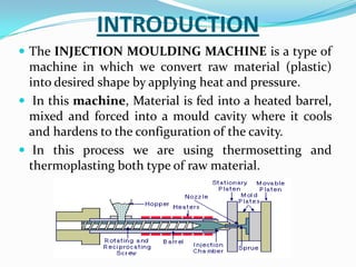
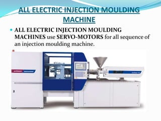
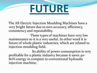
This document provides information about the study and operation of all electric injection molding machines. It discusses the history of injection molding machines, describes the key components and operation of all electric machines, and compares them to hydraulic injection molding machines. All electric injection molding machines use servomotors to control each function, providing greater precision and accuracy than hydraulic machines while using 40-80% less energy. Maintenance of all electric machines focuses on preventative maintenance of components like sensors and motors.
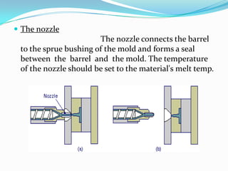
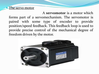


![MTech Seminar Presentation [IIT-Bombay]](https://cdn.slidesharecdn.com/ss_thumbnails/seminar-presentation-final-140502111554-phpapp02-thumbnail.jpg?width=640&height=640&fit=bounds)


