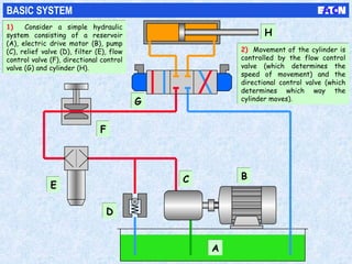
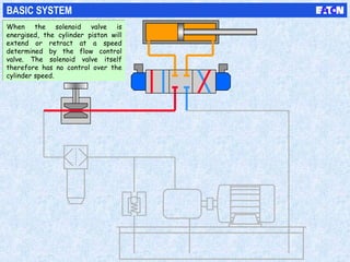
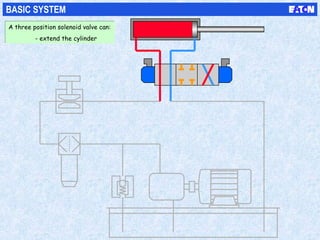
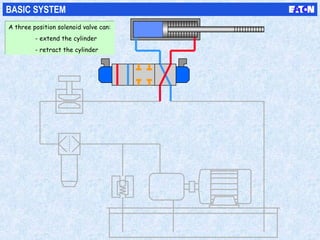
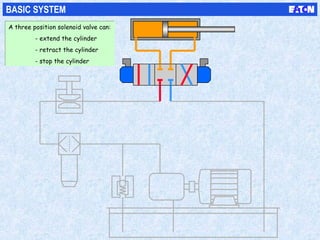
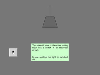
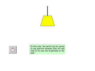
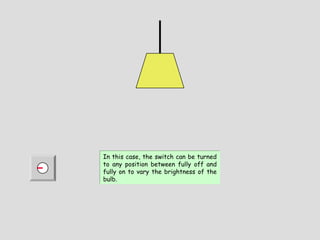
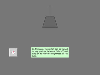
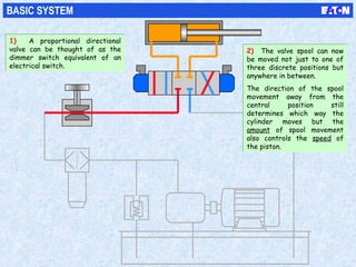
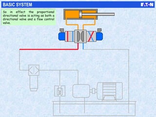
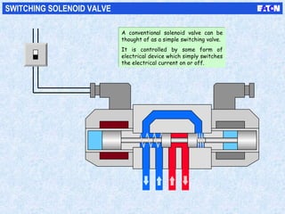
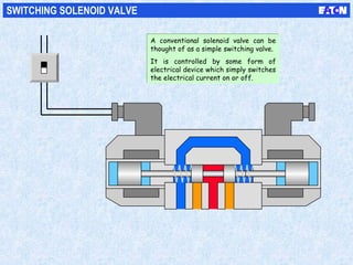
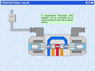
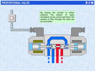
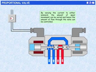
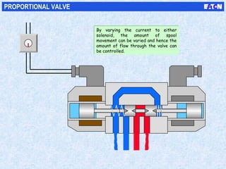
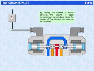
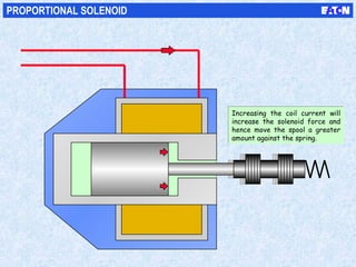
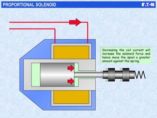
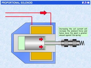
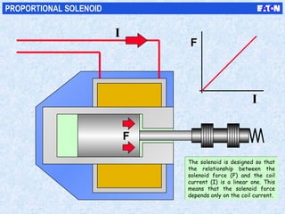
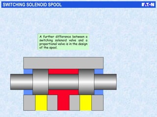
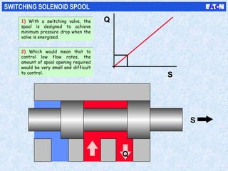
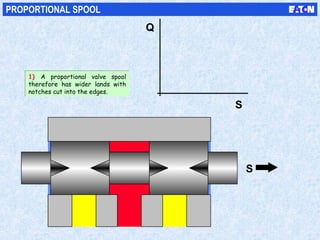
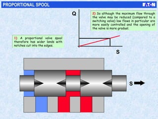
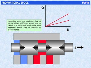
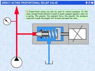
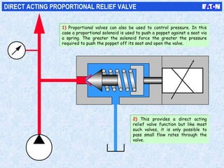
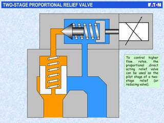
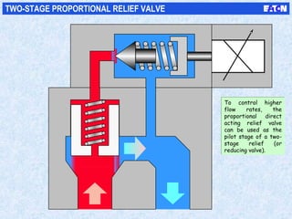
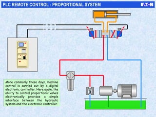
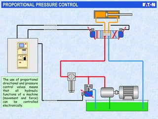
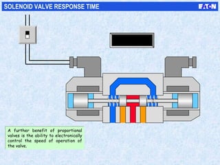
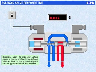
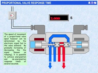
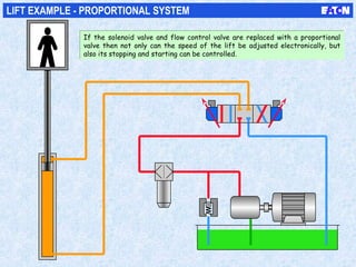
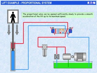
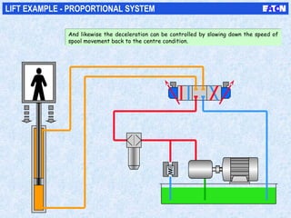
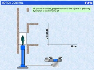
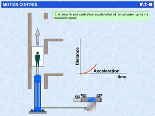
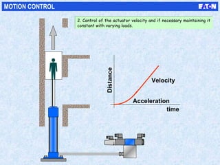
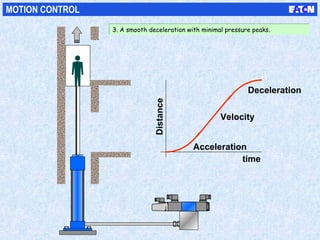
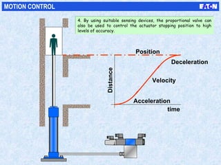
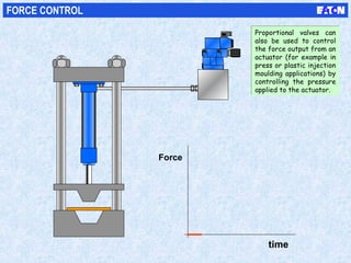
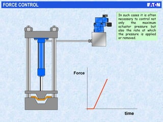
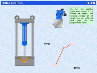
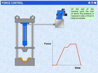
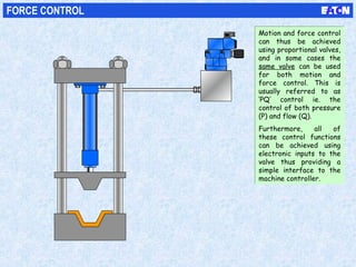
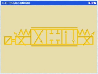
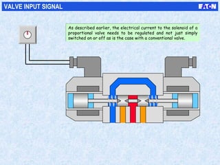
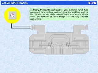
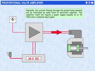
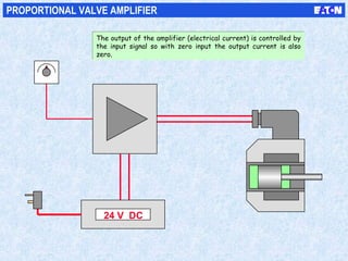
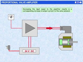
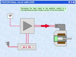
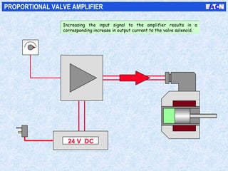
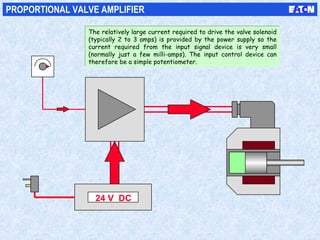
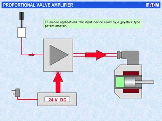
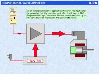
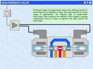
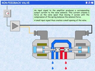
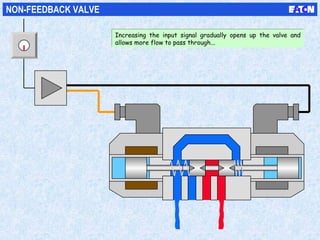
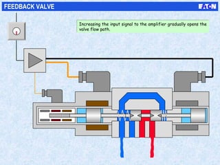
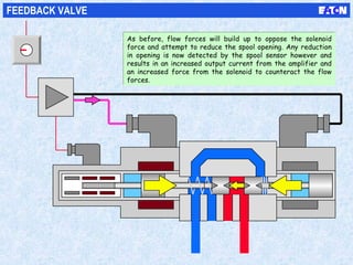
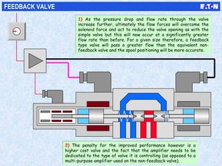
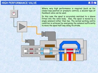
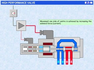
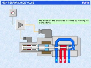
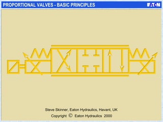
This document discusses proportional valves and their basic principles. It explains that a proportional directional valve can control both the direction and speed of a hydraulic cylinder's movement by varying the position of the valve spool, similar to a dimmer switch controlling light brightness. A proportional solenoid valve uses a solenoid whose force on the spool is proportional to the electric current, allowing varying degrees of spool movement and thus variable flow control. The spool design incorporates notches to better facilitate control of low flow rates. Proportional valves can also be used to regulate hydraulic system pressure.
The pressure energy is fed to the actuator through a number of control block called valves.
• Various type of valve are used in hydraulic system to control or regulate the flow medium.
• Basicallyvalvesareexpectedtocontrol: – Direction
– Pressure
– Flow
– Otherspecialfunctions.
Hydraulic Valves and Hydraulic System AccessoriesRAHUL THAKER
Hydraulic Valves and Hydraulic System Accessories:
Direction control valves,Pressure control valves, Flow control valves, Non-return valves, Reservoirs,Accumulators, Heating & cooling devices, Hoses. Selection of valves for circuits.
In hydraulic and pneumatic systems flow control valves are necessary to vary the speed of actuator. Flow control valves are placed in between Actuator and Direction Control (DC) Valve
Control of a single-acting and double-acting cylinder, regeneration, motor braking, speed control, synchronisation, fail safe, two handed, application of counterbalance, sequence, unloading, pressure reducing, pilot operated check valve
Hydraulic Systems are very delicate systems, if contamination enters the systems failure will occur in the form of partial functional failure or total functional failure.
Training, education, and standardization is the only path to success. It is all about the "Failure Modes" and their causes.
This short assortment of slides provides recommended actions to solve these problems at the end.
Good Luck and God Speed.
Electro hydraulic system Components and their operationSrichandan Subudhi
After this presentation you will be knowing:
1.What are DCVs, its type and their uses
2.About Check Valves and pilot controlled check valves
3.What are solenoid actuated valves and their operation
4.What are proportional solenoid valves and their operation
5.Servo Valve Operation
6.Servo Valve Connector
electric control valve actuator
electric control air valve
electric heater control valve auto
electric flow control valve autoclave
arag electric control valves
steam control valves electric actuators
electric actuated flow control valves
electric control butterfly valve
electric control ball valve
electric boom control valves
electric control valve definition
electric hydraulic directional control valves
electronic throttle control exhaust valve
electric control valves for water
electric flow control valves
electric control for hydraulic valves
electric actuators for control valves
electric actuated flow control valves
electric hydraulic flow control valves
fisher electric control valves
electric control gas valve
general electric control valves
electric control valve hydraulic
electric flow control hydraulic valve
electric over hydraulic control valves
electric hydraulic directional control valves
electric control valves manufacturers
electric over hydraulic control valves
electronic control valve pdf
electric control valve price
electric control valve positioner
electric proportional control valves
electro pneumatic control valves
precision electric control valves
electric vs pneumatic control valves
electronic control radiator valves
electric control valve suppliers
electric control valve symbol
electric control solenoid valve
electric sprayer control valves
schneider electric control valves
electric steam control valves
electric sprayer control system 3 solenoid valves
steam control valves electric actuators
electric vs pneumatic control valves
electric control valves water
control valves with electric actuators
steam control valves with electric actuators
electric vs pneumatic control valves
Educaterer India is an unique combination of passion driven into a hobby which makes an awesome profession. We carve the lives of enthusiastic candidates to a perfect professional who can impress upon the mindsets of the industry, while following the established traditions, can dare to set new standards to follow. We don't want you to be the part of the crowd, rather we like to make you the reason of the crowd.
Today's Effort For A Better Tomorrow
Everything you want to know about Liquid LensesLikan Patra
Liquid lens technology has a wide range of applications. Because the liquid lens is so small, light and inexpensive, it can easily be incorporated into a variety of objects. Soon every laptop might come with a built in webcam made from a liquid lens. One of the few disadvantages of a liquid lens made with water is that it is subject to freezing at low temperatures. If you have a cell phone or camera with a liquid lens, be careful not to expose it to very cold temperatures for long periods of time, or you could damage your liquid lens by freezing the water inside it.
Parker solenoid valves include types and configurations for a wide variety of hydraulic, pneumatic, instrumentation, medical, refrigeration and aerospace applications. Solenoid valve solutions offer reliability, fast and safe switching and compact designs suitable for challenging environments.
Modeling and Simulation of Closed Loop Controlled Parallel Cascaded Buck Boos...IJPEDS-IAES
This Work deals with design, modeling and simulation of parallel cascaded
buck boost converter inverter based closed loop controlled solar system. Two
buck boost converters are cascaded in parallel to reduce the ripple in DC
output. The DC from the solar cell is stepped up using boost converter. The
output of the boost converter is converted to 50Hz AC using single phase full
bridge inverter. The simulation results of open loop and closed loop systems
are compared. This paper has presented a simulink model for closed loop
controlled solar system. Parallel cascaded buck boost converter is proposed
for solar system.
On Load Tap Changer (OLTC) is used in "High Power Transformers" to control output voltage, when electric load on transformers get increase the output voltage get decrease due to internal voltage drop inside winding, change in tap is required to maintain output voltage. OLTC is a device which perform tap changing in High Power Transformers during On Load conditions and is powered by a motor.
In electrical engineering, a switch is an electrical component that can "make" or "break" an electrical circuit, interrupting the currentor diverting it from one conductor to another.The mechanism of a switch removes or restores the conducting path in a circuit
when it is operated. It may be operated manually, for example, a light switch or a keyboard button, may be operated by a moving
object such as a door, or may be operated by some sensing element for pressure, temperature or flow. A switch will have one or more
sets of contacts, which may operate simultaneously, sequentially, or alternately. Switches in high-powered circuits must operate
rapidly to prevent destructive arcing, and may include special features to assist in rapidly interrupting a heavy current. Multiple forms
of actuators are used for operation by hand or to sense position, level, temperature or flow.Special types are used, for example, for control of machinery, to reverse electric motors, or to sense liquid level. Many specialized forms exist. A common use is control of
lighting, where multiple switches may be wired into one circuit to allow convenient control of light fixtures.
By analogy with the devices that select one or more possible paths for electric currents, devices that route information in a computer
network are also called "switches" - these are usually more complicated than simple electromechanical toggles or pushbutton devices, and operate without direct human interaction.
We all have good and bad thoughts from time to time and situation to situation. We are bombarded daily with spiraling thoughts(both negative and positive) creating all-consuming feel , making us difficult to manage with associated suffering. Good thoughts are like our Mob Signal (Positive thought) amidst noise(negative thought) in the atmosphere. Negative thoughts like noise outweigh positive thoughts. These thoughts often create unwanted confusion, trouble, stress and frustration in our mind as well as chaos in our physical world. Negative thoughts are also known as “distorted thinking”.
The French Revolution, which began in 1789, was a period of radical social and political upheaval in France. It marked the decline of absolute monarchies, the rise of secular and democratic republics, and the eventual rise of Napoleon Bonaparte. This revolutionary period is crucial in understanding the transition from feudalism to modernity in Europe.
For more information, visit-www.vavaclasses.com
Welcome to TechSoup New Member Orientation and Q&A (May 2024).pdfTechSoup
In this webinar you will learn how your organization can access TechSoup's wide variety of product discount and donation programs. From hardware to software, we'll give you a tour of the tools available to help your nonprofit with productivity, collaboration, financial management, donor tracking, security, and more.
Students, digital devices and success - Andreas Schleicher - 27 May 2024..pptxEduSkills OECD
Andreas Schleicher presents at the OECD webinar ‘Digital devices in schools: detrimental distraction or secret to success?’ on 27 May 2024. The presentation was based on findings from PISA 2022 results and the webinar helped launch the PISA in Focus ‘Managing screen time: How to protect and equip students against distraction’ https://www.oecd-ilibrary.org/education/managing-screen-time_7c225af4-en and the OECD Education Policy Perspective ‘Students, digital devices and success’ can be found here - https://oe.cd/il/5yV
Instructions for Submissions thorugh G- Classroom.pptxJheel Barad
This presentation provides a briefing on how to upload submissions and documents in Google Classroom. It was prepared as part of an orientation for new Sainik School in-service teacher trainees. As a training officer, my goal is to ensure that you are comfortable and proficient with this essential tool for managing assignments and fostering student engagement.
The Indian economy is classified into different sectors to simplify the analysis and understanding of economic activities. For Class 10, it's essential to grasp the sectors of the Indian economy, understand their characteristics, and recognize their importance. This guide will provide detailed notes on the Sectors of the Indian Economy Class 10, using specific long-tail keywords to enhance comprehension.
For more information, visit-www.vavaclasses.com
How to Split Bills in the Odoo 17 POS ModuleCeline George
Bills have a main role in point of sale procedure. It will help to track sales, handling payments and giving receipts to customers. Bill splitting also has an important role in POS. For example, If some friends come together for dinner and if they want to divide the bill then it is possible by POS bill splitting. This slide will show how to split bills in odoo 17 POS.
The Art Pastor's Guide to Sabbath | Steve ThomasonSteve Thomason
What is the purpose of the Sabbath Law in the Torah. It is interesting to compare how the context of the law shifts from Exodus to Deuteronomy. Who gets to rest, and why?
2. BASIC SYSTEM
1) Consider a simple hydraulic
system consisting of a reservoir
(A), electric drive motor (B), pump
(C), relief valve (D), filter (E), flow
control valve (F), directional control
valve (G) and cylinder (H).
1) Consider a simple hydraulic
system consisting of a reservoir
(A), electric drive motor (B), pump
(C), relief valve (D), filter (E), flow
control valve (F), directional control
valve (G) and cylinder (H).
2) Movement of the cylinder is
controlled by the flow control
valve (which determines the
speed of movement) and the
directional control valve (which
determines which way the
cylinder moves).
2) Movement of the cylinder is
controlled by the flow control
valve (which determines the
speed of movement) and the
directional control valve (which
determines which way the
cylinder moves).
AA
BBCC
DD
EE
FF
HH
GG
3. BASIC SYSTEM
When the solenoid valve is
energised, the cylinder piston will
extend or retract at a speed
determined by the flow control
valve. The solenoid valve itself
therefore has no control over the
cylinder speed.
When the solenoid valve is
energised, the cylinder piston will
extend or retract at a speed
determined by the flow control
valve. The solenoid valve itself
therefore has no control over the
cylinder speed.
4. BASIC SYSTEM
A three position solenoid valve can:
- extend the cylinder
A three position solenoid valve can:
- extend the cylinder
5. BASIC SYSTEM
A three position solenoid valve can:
- extend the cylinder
- retract the cylinder
A three position solenoid valve can:
- extend the cylinder
- retract the cylinder
6. BASIC SYSTEM
A three position solenoid valve can:
- extend the cylinder
- retract the cylinder
- stop the cylinder
A three position solenoid valve can:
- extend the cylinder
- retract the cylinder
- stop the cylinder
7. The solenoid valve is therefore acting
much like a switch in an electrical
circuit.
In one position the light is switched
off...
The solenoid valve is therefore acting
much like a switch in an electrical
circuit.
In one position the light is switched
off...
8. ... and in the other position it is
switched on but there are no
intermediate states.
... and in the other position it is
switched on but there are no
intermediate states.
9. However, another type of switch can
be used for controlling a light bulb
known as a dimmer switch.
However, another type of switch can
be used for controlling a light bulb
known as a dimmer switch.
10. In this case, the switch can be turned
to any position between fully off and
fully on to vary the brightness of the
bulb.
In this case, the switch can be turned
to any position between fully off and
fully on to vary the brightness of the
bulb.
11. In this case, the switch can be turned
to any position between fully off and
fully on to vary the brightness of the
bulb.
In this case, the switch can be turned
to any position between fully off and
fully on to vary the brightness of the
bulb.
12. In this case, the switch can be turned
to any position between fully off and
fully on to vary the brightness of the
bulb.
In this case, the switch can be turned
to any position between fully off and
fully on to vary the brightness of the
bulb.
13. In this case, the switch can be turned
to any position between fully off and
fully on to vary the brightness of the
bulb.
In this case, the switch can be turned
to any position between fully off and
fully on to vary the brightness of the
bulb.
14. In this case, the switch can be turned
to any position between fully off and
fully on to vary the brightness of the
bulb.
In this case, the switch can be turned
to any position between fully off and
fully on to vary the brightness of the
bulb.
15. In this case, the switch can be turned
to any position between fully off and
fully on to vary the brightness of the
bulb.
In this case, the switch can be turned
to any position between fully off and
fully on to vary the brightness of the
bulb.
16. In this case, the switch can be turned
to any position between fully off and
fully on to vary the brightness of the
bulb.
In this case, the switch can be turned
to any position between fully off and
fully on to vary the brightness of the
bulb.
17. In this case, the switch can be turned
to any position between fully off and
fully on to vary the brightness of the
bulb.
In this case, the switch can be turned
to any position between fully off and
fully on to vary the brightness of the
bulb.
18. BASIC SYSTEM
2) The valve spool can now
be moved not just to one of
three discrete positions but
anywhere in between.
The direction of the spool
movement away from the
central position still
determines which way the
cylinder moves but the
amount of spool movement
also controls the speed of
the piston.
2) The valve spool can now
be moved not just to one of
three discrete positions but
anywhere in between.
The direction of the spool
movement away from the
central position still
determines which way the
cylinder moves but the
amount of spool movement
also controls the speed of
the piston.
1) A proportional directional
valve can be thought of as the
dimmer switch equivalent of an
electrical switch.
1) A proportional directional
valve can be thought of as the
dimmer switch equivalent of an
electrical switch.
19. BASIC SYSTEM
So in effect the proportional
directional valve is acting as both a
directional valve and a flow control
valve.
So in effect the proportional
directional valve is acting as both a
directional valve and a flow control
valve.
20. SWITCHING SOLENOID VALVE
A conventional solenoid valve can be
thought of as a simple switching valve.
It is controlled by some form of
electrical device which simply switches
the electrical current on or off.
A conventional solenoid valve can be
thought of as a simple switching valve.
It is controlled by some form of
electrical device which simply switches
the electrical current on or off.
21. SWITCHING SOLENOID VALVE
A conventional solenoid valve can be
thought of as a simple switching valve.
It is controlled by some form of
electrical device which simply switches
the electrical current on or off.
A conventional solenoid valve can be
thought of as a simple switching valve.
It is controlled by some form of
electrical device which simply switches
the electrical current on or off.
22. SWITCHING SOLENOID VALVE
A conventional solenoid valve can be
thought of as a simple switching valve.
It is controlled by some form of
electrical device which simply switches
the electrical current on or off.
A conventional solenoid valve can be
thought of as a simple switching valve.
It is controlled by some form of
electrical device which simply switches
the electrical current on or off.
23. PROPORTIONAL VALVE
A proportional directional valve
however will be controlled by an
electrical device more like a dimmer
switch.
A proportional directional valve
however will be controlled by an
electrical device more like a dimmer
switch.
24. PROPORTIONAL VALVE
By varying the current to either
solenoid, the amount of spool
movement can be varied and hence the
amount of flow through the valve can
be controlled.
By varying the current to either
solenoid, the amount of spool
movement can be varied and hence the
amount of flow through the valve can
be controlled.
25. PROPORTIONAL VALVE
By varying the current to either
solenoid, the amount of spool
movement can be varied and hence the
amount of flow through the valve can
be controlled.
By varying the current to either
solenoid, the amount of spool
movement can be varied and hence the
amount of flow through the valve can
be controlled.
26. PROPORTIONAL VALVE
By varying the current to either
solenoid, the amount of spool
movement can be varied and hence the
amount of flow through the valve can
be controlled.
By varying the current to either
solenoid, the amount of spool
movement can be varied and hence the
amount of flow through the valve can
be controlled.
27. PROPORTIONAL VALVE
By varying the current to either
solenoid, the amount of spool
movement can be varied and hence the
amount of flow through the valve can
be controlled.
By varying the current to either
solenoid, the amount of spool
movement can be varied and hence the
amount of flow through the valve can
be controlled.
28. PROPORTIONAL VALVE
By varying the current to either
solenoid, the amount of spool
movement can be varied and hence the
amount of flow through the valve can
be controlled.
By varying the current to either
solenoid, the amount of spool
movement can be varied and hence the
amount of flow through the valve can
be controlled.
29. PROPORTIONAL VALVE
By varying the current to either
solenoid, the amount of spool
movement can be varied and hence the
amount of flow through the valve can
be controlled.
By varying the current to either
solenoid, the amount of spool
movement can be varied and hence the
amount of flow through the valve can
be controlled.
30. PROPORTIONAL SOLENOID
So unlike a conventional
solenoid valve, the electrical
current flowing through the
coil of a proportional valve
needs to be regulated not
just switched on or off.
The construction of a
proportional solenoid is
however similar to that of an
on/off solenoid.
The solenoid consists of:
- a coil (A)
- a frame (B)
- an armature (C)
- a pole piece (D)
- a push-pin (E)
The armature is enclosed in a
core tube (F) and the whole
assembly is often fully
encapsulated in a plastic resin
material (G).
AA
BB
CC
DDFF
GG
EE
31. PROPORTIONAL SOLENOID
When a voltage is applied to the
coil connections, an electrical
current will flow through the
coil.
When a voltage is applied to the
coil connections, an electrical
current will flow through the
coil.
32. PROPORTIONAL SOLENOID
1) In turn, the electrical current
creates a magnetic field which is
concentrated in the metal frame,
pole piece and armature.
1) In turn, the electrical current
creates a magnetic field which is
concentrated in the metal frame,
pole piece and armature.
2) There is however a gap in the
magnetic circuit between the
pole piece and armature so a
force is created which acts to
close this gap and complete the
magnetic circuit.
2) There is however a gap in the
magnetic circuit between the
pole piece and armature so a
force is created which acts to
close this gap and complete the
magnetic circuit.
33. PROPORTIONAL SOLENOID
1) The push-pin connects the
solenoid to the valve spool and
normally moves the spool against
a spring.
1) The push-pin connects the
solenoid to the valve spool and
normally moves the spool against
a spring.
2) The force created by the
solenoid is determined by the
strength of the magnetic field
which itself is proportional to
the current flowing through the
coil.
2) The force created by the
solenoid is determined by the
strength of the magnetic field
which itself is proportional to
the current flowing through the
coil.
34. PROPORTIONAL SOLENOID
Increasing the coil current will
increase the solenoid force and
hence move the spool a greater
amount against the spring.
Increasing the coil current will
increase the solenoid force and
hence move the spool a greater
amount against the spring.
35. PROPORTIONAL SOLENOID
Increasing the coil current will
increase the solenoid force and
hence move the spool a greater
amount against the spring.
Increasing the coil current will
increase the solenoid force and
hence move the spool a greater
amount against the spring.
36. PROPORTIONAL SOLENOID
Increasing the coil current will
increase the solenoid force and
hence move the spool a greater
amount against the spring.
Increasing the coil current will
increase the solenoid force and
hence move the spool a greater
amount against the spring.
37. F
I
F
I
PROPORTIONAL SOLENOID
The solenoid is designed so that
the relationship between the
solenoid force (F) and the coil
current (I) is a linear one. This
means that the solenoid force
depends only on the coil current.
The solenoid is designed so that
the relationship between the
solenoid force (F) and the coil
current (I) is a linear one. This
means that the solenoid force
depends only on the coil current.
38. SWITCHING SOLENOID SPOOL
A further difference between a
switching solenoid valve and a
proportional valve is in the design
of the spool.
A further difference between a
switching solenoid valve and a
proportional valve is in the design
of the spool.
39. S
S
Q
Q
SWITCHING SOLENOID SPOOL
1) With a switching valve, the
spool is designed to achieve
minimum pressure drop when the
valve is energised.
1) With a switching valve, the
spool is designed to achieve
minimum pressure drop when the
valve is energised.
2) Which would mean that to
control low flow rates, the
amount of spool opening required
would be very small and difficult
to control.
2) Which would mean that to
control low flow rates, the
amount of spool opening required
would be very small and difficult
to control.
40. S
S
Q
PROPORTIONAL SPOOL
1) A proportional valve spool
therefore has wider lands with
notches cut into the edges.
1) A proportional valve spool
therefore has wider lands with
notches cut into the edges.
41. S
S
Q
PROPORTIONAL SPOOL
1) A proportional valve spool
therefore has wider lands with
notches cut into the edges.
1) A proportional valve spool
therefore has wider lands with
notches cut into the edges.
2) So although the maximum flow through
the valve may be reduced (compared to a
switching valve) low flows in particular are
more easily controlled and the opening of
the valve is more gradual.
2) So although the maximum flow through
the valve may be reduced (compared to a
switching valve) low flows in particular are
more easily controlled and the opening of
the valve is more gradual.
42. S
S
Q
PROPORTIONAL SPOOL
Depending upon the maximum flow to
be controlled, different spools can be
fitted to a particular valve which have
different shape, size or number of
spool notches.
Depending upon the maximum flow to
be controlled, different spools can be
fitted to a particular valve which have
different shape, size or number of
spool notches.
43. DIRECT ACTING PROPORTIONAL RELIEF VALVE
1) Proportional valves can also be used to control pressure. In this
case a proportional solenoid is used to push a poppet against a seat via
a spring. The greater the solenoid force the greater the pressure
required to push the poppet off its seat and open the valve.
1) Proportional valves can also be used to control pressure. In this
case a proportional solenoid is used to push a poppet against a seat via
a spring. The greater the solenoid force the greater the pressure
required to push the poppet off its seat and open the valve.
44. DIRECT ACTING PROPORTIONAL RELIEF VALVE
2) This provides a direct acting
relief valve function but like most
such valves, it is only possible to
pass small flow rates through the
valve.
2) This provides a direct acting
relief valve function but like most
such valves, it is only possible to
pass small flow rates through the
valve.
1) Proportional valves can also be used to control pressure. In this
case a proportional solenoid is used to push a poppet against a seat via
a spring. The greater the solenoid force the greater the pressure
required to push the poppet off its seat and open the valve.
1) Proportional valves can also be used to control pressure. In this
case a proportional solenoid is used to push a poppet against a seat via
a spring. The greater the solenoid force the greater the pressure
required to push the poppet off its seat and open the valve.
45. TWO-STAGE PROPORTIONAL RELIEF VALVE
To control higher
flow rates, the
proportional direct
acting relief valve
can be used as the
pilot stage of a two-
stage relief (or
reducing valve).
To control higher
flow rates, the
proportional direct
acting relief valve
can be used as the
pilot stage of a two-
stage relief (or
reducing valve).
46. TWO-STAGE PROPORTIONAL RELIEF VALVE
To control higher
flow rates, the
proportional direct
acting relief valve
can be used as the
pilot stage of a two-
stage relief (or
reducing valve).
To control higher
flow rates, the
proportional direct
acting relief valve
can be used as the
pilot stage of a two-
stage relief (or
reducing valve).
48. REMOTE CONTROL - CONVENTIONAL SYSTEM
In order to adjust the speed of
an actuator in a conventional
system, the flow control valve has
to be mounted in a convenient or
accessible position. This may
often mean running high pressure
hydraulic pipes to and from an
operator’s desk.
In order to adjust the speed of
an actuator in a conventional
system, the flow control valve has
to be mounted in a convenient or
accessible position. This may
often mean running high pressure
hydraulic pipes to and from an
operator’s desk.
49. REMOTE CONTROL - PROPORTIONAL SYSTEM
With a proportional system however,
where control valve adjustment is
electronic, only low-power electrical
cables need to be connected
between the operator’s desk and the
valve.
With a proportional system however,
where control valve adjustment is
electronic, only low-power electrical
cables need to be connected
between the operator’s desk and the
valve.
50. PLC REMOTE CONTROL - PROPORTIONAL SYSTEM
More commonly these days, machine
control is carried out by a digital
electronic controller. Here again, the
ability to control proportional valves
electronically provides a simple
interface between the hydraulic
system and the electronic controller.
More commonly these days, machine
control is carried out by a digital
electronic controller. Here again, the
ability to control proportional valves
electronically provides a simple
interface between the hydraulic
system and the electronic controller.
51. PROPORTIONAL PRESSURE CONTROL
The use of proportional
directional and pressure
control valves means
that all hydraulic
functions of a machine
(movement and force)
can be controlled
electronically.
The use of proportional
directional and pressure
control valves means
that all hydraulic
functions of a machine
(movement and force)
can be controlled
electronically.
52. SOLENOID VALVE RESPONSE TIME
A further benefit of proportional
valves is the ability to electronically
control the speed of operation of
the valve.
A further benefit of proportional
valves is the ability to electronically
control the speed of operation of
the valve.
53. 0.015 S
SOLENOID VALVE RESPONSE TIME
Depending upon its size and voltage
supply, a conventional switching solenoid
valve will have an energisation response
time of approximately 15 milli-seconds.
Depending upon its size and voltage
supply, a conventional switching solenoid
valve will have an energisation response
time of approximately 15 milli-seconds.
54. 0.040 S
SOLENOID VALVE RESPONSE TIME
The de-energisation response time will
be only slightly slower (typically around
25 ms) since the return spring produces
less force than the solenoid .
The de-energisation response time will
be only slightly slower (typically around
25 ms) since the return spring produces
less force than the solenoid .
55. S
PROPORTIONAL VALVE RESPONSE TIME
The speed of movement
of a proportional valve
spool however can be
determined by the
electronic signal fed to
the valve solenoid. By
gradually increasing or
decreasing the the
signal (known as
ramping), it is possible
to achieve energisation
and de-energisation
response times of
several seconds.
The speed of movement
of a proportional valve
spool however can be
determined by the
electronic signal fed to
the valve solenoid. By
gradually increasing or
decreasing the the
signal (known as
ramping), it is possible
to achieve energisation
and de-energisation
response times of
several seconds.
56. 1.000 S
PROPORTIONAL VALVE RESPONSE TIME
The speed of movement
of a proportional valve
spool however can be
determined by the
electronic signal fed to
the valve solenoid. By
gradually increasing or
decreasing the the
signal (known as
ramping), it is possible
to achieve energisation
and de-energisation
response times of
several seconds.
The speed of movement
of a proportional valve
spool however can be
determined by the
electronic signal fed to
the valve solenoid. By
gradually increasing or
decreasing the the
signal (known as
ramping), it is possible
to achieve energisation
and de-energisation
response times of
several seconds.
57. 2.000 S
PROPORTIONAL VALVE RESPONSE TIME
The speed of movement
of a proportional valve
spool however can be
determined by the
electronic signal fed to
the valve solenoid. By
gradually increasing or
decreasing the the
signal (known as
ramping), it is possible
to achieve energisation
and de-energisation
response times of
several seconds.
The speed of movement
of a proportional valve
spool however can be
determined by the
electronic signal fed to
the valve solenoid. By
gradually increasing or
decreasing the the
signal (known as
ramping), it is possible
to achieve energisation
and de-energisation
response times of
several seconds.
58. 3.000 S
PROPORTIONAL VALVE RESPONSE TIME
The speed of movement
of a proportional valve
spool however can be
determined by the
electronic signal fed to
the valve solenoid. By
gradually increasing or
decreasing the the
signal (known as
ramping), it is possible
to achieve energisation
and de-energisation
response times of
several seconds.
The speed of movement
of a proportional valve
spool however can be
determined by the
electronic signal fed to
the valve solenoid. By
gradually increasing or
decreasing the the
signal (known as
ramping), it is possible
to achieve energisation
and de-energisation
response times of
several seconds.
59. LIFT EXAMPLE - CONVENTIONAL SYSTEM
The reason why it is useful to be able to control the speed of spool movement
of a valve is to reduce shock in a system. This is achieved by controlling the
acceleration and deceleration of the actuator. Suppose, for example, that the
simple hydraulic system described earlier is used to operate a passenger lift in
a hotel.
60. LIFT EXAMPLE - CONVENTIONAL SYSTEM
When the solenoid valve is energised to lower the lift, the valve spool will move
across very rapidly. This means that the cylinder will accelerate very quickly
up to its maximum speed (determined by the setting of flow control valve F).
This sudden starting of the lift provides a very uncomfortable ride for its
occupants.
FF
61. LIFT EXAMPLE - CONVENTIONAL SYSTEM
Similarly, when the lift reaches its destination, the solenoid valve will shut off
very rapidly causing a sudden stopping of the lift and again a very
uncomfortable situation for the occupants. In real hydraulic systems, the
shocks generated by sudden starting and stopping of actuators create high
peak pressures which are one of the principle causes of fluid leakage.
62. LIFT EXAMPLE - PROPORTIONAL SYSTEM
If the solenoid valve and flow control valve are replaced with a proportional
valve then not only can the speed of the lift be adjusted electronically, but
also its stopping and starting can be controlled.
If the solenoid valve and flow control valve are replaced with a proportional
valve then not only can the speed of the lift be adjusted electronically, but
also its stopping and starting can be controlled.
63. LIFT EXAMPLE - PROPORTIONAL SYSTEM
The proportional valve can be opened sufficiently slowly to provide a smooth
acceleration of the lift up to its maximum speed.
The proportional valve can be opened sufficiently slowly to provide a smooth
acceleration of the lift up to its maximum speed.
64. LIFT EXAMPLE - PROPORTIONAL SYSTEM
And likewise the deceleration can be controlled by slowing down the speed of
spool movement back to the centre condition.
And likewise the deceleration can be controlled by slowing down the speed of
spool movement back to the centre condition.
65. timeDistance
MOTION CONTROL
In general therefore, proportional valves are capable of providing
full motion control in terms of:
In general therefore, proportional valves are capable of providing
full motion control in terms of:
66. time
Acceleration
Distance
MOTION CONTROL
1. A smooth and controlled acceleration of an actuator up to its
maximum speed.
1. A smooth and controlled acceleration of an actuator up to its
maximum speed.
67. time
Acceleration
Velocity
Distance
MOTION CONTROL
2. Control of the actuator velocity and if necessary maintaining it
constant with varying loads.
2. Control of the actuator velocity and if necessary maintaining it
constant with varying loads.
69. time
Position
Acceleration
Deceleration
Velocity
Distance
MOTION CONTROL
4. By using suitable sensing devices, the proportional valve can
also be used to control the actuator stopping position to high
levels of accuracy.
4. By using suitable sensing devices, the proportional valve can
also be used to control the actuator stopping position to high
levels of accuracy.
70. time
Force
FORCE CONTROL
Proportional valves can
also be used to control
the force output from an
actuator (for example in
press or plastic injection
moulding applications) by
controlling the pressure
applied to the actuator.
Proportional valves can
also be used to control
the force output from an
actuator (for example in
press or plastic injection
moulding applications) by
controlling the pressure
applied to the actuator.
71. time
Force
FORCE CONTROL
In such cases it is often
necessary to control not
only the maximum
actuator pressure but
also the rate at which
the pressure is applied
or removed.
In such cases it is often
necessary to control not
only the maximum
actuator pressure but
also the rate at which
the pressure is applied
or removed.
72. time
Force
FORCE CONTROL
In fact the machine
cycle may consist of a
series of ramps and
holding periods all of
which can be achieved
with just the one
proportional valve.
In fact the machine
cycle may consist of a
series of ramps and
holding periods all of
which can be achieved
with just the one
proportional valve.
73. time
Force
FORCE CONTROL
At the end of the
machine cycle the rate
at which the pressure is
reduced is also critical in
many processes.
At the end of the
machine cycle the rate
at which the pressure is
reduced is also critical in
many processes.
74. FORCE CONTROL
Motion and force control
can thus be achieved
using proportional valves,
and in some cases the
same valve can be used
for both motion and
force control. This is
usually referred to as
‘PQ’ control ie. the
control of both pressure
(P) and flow (Q).
Furthermore, all of
these control functions
can be achieved using
electronic inputs to the
valve thus providing a
simple interface to the
machine controller.
76. VALVE INPUT SIGNAL
As described earlier, the electrical current to the solenoid of a
proportional valve needs to be regulated and not just simply
switched on or off as is the case with a conventional valve.
As described earlier, the electrical current to the solenoid of a
proportional valve needs to be regulated and not just simply
switched on or off as is the case with a conventional valve.
77. VALVE INPUT SIGNAL
In theory, this could be achieved by using a dimmer switch type
component (ie. a variable resistor). Practical problems such as
heat generation and drift however mean that such a device
would not normally be used except for the very simplest
applications.
In theory, this could be achieved by using a dimmer switch type
component (ie. a variable resistor). Practical problems such as
heat generation and drift however mean that such a device
would not normally be used except for the very simplest
applications.
78. 24 V DC
PROPORTIONAL VALVE AMPLIFIER
Normally, the current flowing through the proportional solenoid
will be controlled by some form of electronic amplifier. The
amplifier itself will require a power supply (usually 12 or 24
VDC) and a command input signal.
Normally, the current flowing through the proportional solenoid
will be controlled by some form of electronic amplifier. The
amplifier itself will require a power supply (usually 12 or 24
VDC) and a command input signal.
79. 24 V DC
PROPORTIONAL VALVE AMPLIFIER
The output of the amplifier (electrical current) is controlled by
the input signal so with zero input the output current is also
zero.
The output of the amplifier (electrical current) is controlled by
the input signal so with zero input the output current is also
zero.
80. 24 V DC
PROPORTIONAL VALVE AMPLIFIER
Increasing the input signal to the amplifier results in a
corresponding increase in output current to the valve solenoid.
Increasing the input signal to the amplifier results in a
corresponding increase in output current to the valve solenoid.
81. 24 V DC
PROPORTIONAL VALVE AMPLIFIER
Increasing the input signal to the amplifier results in a
corresponding increase in output current to the valve solenoid.
Increasing the input signal to the amplifier results in a
corresponding increase in output current to the valve solenoid.
82. 24 V DC
PROPORTIONAL VALVE AMPLIFIER
Increasing the input signal to the amplifier results in a
corresponding increase in output current to the valve solenoid.
Increasing the input signal to the amplifier results in a
corresponding increase in output current to the valve solenoid.
83. 24 V DC
PROPORTIONAL VALVE AMPLIFIER
The relatively large current required to drive the valve solenoid
(typically 2 to 3 amps) is provided by the power supply so the
current required from the input signal device is very small
(normally just a few milli-amps). The input control device can
therefore be a simple potentiometer.
The relatively large current required to drive the valve solenoid
(typically 2 to 3 amps) is provided by the power supply so the
current required from the input signal device is very small
(normally just a few milli-amps). The input control device can
therefore be a simple potentiometer.
84. 24 V DC
PROPORTIONAL VALVE AMPLIFIER
In mobile applications the input device could by a joystick type
potentiometer.
In mobile applications the input device could by a joystick type
potentiometer.
85. 24 V DC
PROPORTIONAL VALVE AMPLIFIER
In an increasing number of applications however, the input signal
is generated by the machine controller itself (eg. a PLC -
Programmable Logic Controller). This can then be fed directly to
the valve amplifier to generate the appropriate output.
In an increasing number of applications however, the input signal
is generated by the machine controller itself (eg. a PLC -
Programmable Logic Controller). This can then be fed directly to
the valve amplifier to generate the appropriate output.
87. NON-FEEDBACK VALVE
Different types of proportional valves with differing levels of
performance are available to meet the requirements of a wide
range of applications. The simplest type of proportional
directional valve balances the solenoid force against a spring
compression force in order to position the spool within the
valve body.
88. NON-FEEDBACK VALVE
An input signal to the amplifier produces a corresponding
output current to the valve solenoid. This current creates a
force on the valve spool thus moving it across until the
compression of the spring balances the solenoid force.
A small input signal thus creates a small opening of the valve.
An input signal to the amplifier produces a corresponding
output current to the valve solenoid. This current creates a
force on the valve spool thus moving it across until the
compression of the spring balances the solenoid force.
A small input signal thus creates a small opening of the valve.
89. NON-FEEDBACK VALVE
Increasing the input signal gradually opens up the valve and
allows more flow to pass through...
Increasing the input signal gradually opens up the valve and
allows more flow to pass through...
90. NON-FEEDBACK VALVE
... until the valve is wide open and passing maximum flow.... until the valve is wide open and passing maximum flow.
91. NON-FEEDBACK VALVE
1) For any input signal therefore, the spool is positioned by
balancing solenoid force against spring force. In practice
however, other forces also act on the spool. Flow forces in
particular are generated when flow passes through the valve
and these will act with the spring to oppose the solenoid force
and thus reduce the amount of spool opening.
92. NON-FEEDBACK VALVE
1) For any input signal therefore, the spool is positioned by
balancing solenoid force against spring force. In practice
however, other forces also act on the spool. Flow forces in
particular are generated when flow passes through the valve
and these will act with the spring to oppose the solenoid force
and thus reduce the amount of spool opening.
2) This simple type of
valve will therefore have
limitations both on the
maximum flow rate it can
pass and also with its
performance in terms of
accurate positioning of the
valve spool.
2) This simple type of
valve will therefore have
limitations both on the
maximum flow rate it can
pass and also with its
performance in terms of
accurate positioning of the
valve spool.
93. FEEDBACK VALVE
Valve performance can be increased by adding a spool position
sensor to the valve. This sensor provides an electronic
feedback signal to the amplifier and thus allows the spool to be
positioned much more accurately.
Valve performance can be increased by adding a spool position
sensor to the valve. This sensor provides an electronic
feedback signal to the amplifier and thus allows the spool to be
positioned much more accurately.
94. FEEDBACK VALVE
Increasing the input signal to the amplifier gradually opens the
valve flow path.
Increasing the input signal to the amplifier gradually opens the
valve flow path.
95. FEEDBACK VALVE
Increasing the input signal to the amplifier gradually opens the
valve flow path.
Increasing the input signal to the amplifier gradually opens the
valve flow path.
96. FEEDBACK VALVE
As before, flow forces will build up to oppose the solenoid
force and attempt to reduce the spool opening. Any reduction
in opening is now detected by the spool sensor however and
results in an increased output current from the amplifier and
an increased force from the solenoid to counteract the flow
forces.
97. FEEDBACK VALVE
1) As the pressure drop and flow rate through the valve
increase further, ultimately the flow forces will overcome the
solenoid force and act to reduce the valve opening as with the
simple valve but this will now occur at a significantly greater
flow rate than before. For a given size therefore, a feedback
type valve will pass a greater flow than the equivalent non-
feedback valve and the spool positioning will be more accurate.
2) The penalty for the improved performance however is a
higher cost valve and the fact that the amplifier needs to be
dedicated to the type of valve it is controlling (as opposed to a
multi-purpose amplifier used on the non-feedback valve).
2) The penalty for the improved performance however is a
higher cost valve and the fact that the amplifier needs to be
dedicated to the type of valve it is controlling (as opposed to a
multi-purpose amplifier used on the non-feedback valve).
98. HIGH PERFORMANCE VALVE
Where very high performance is required (such as for
closed loop position or pressure control), a second type of
feedback valve can be used.
In this case the spool is accurately matched to a sleeve
fitted into the valve body. Also, the spool is moved by a
single solenoid rather than two. The normal working centre
condition is achieved by energising the solenoid sufficiently
to move the spool half-way along its stroke.
99. HIGH PERFORMANCE VALVE
Movement one side of centre is achieved by increasing the
solenoid force (current).
Movement one side of centre is achieved by increasing the
solenoid force (current).
100. HIGH PERFORMANCE VALVE
And movement the other side of centre by reducing the
solenoid force.
And movement the other side of centre by reducing the
solenoid force.
101. HIGH PERFORMANCE VALVE
This type of construction provides a very fast acting, high
performance valve but again with the penalty of increased
cost.
The application requirements will therefore dictate which
type of valve is most suited.
This type of construction provides a very fast acting, high
performance valve but again with the penalty of increased
cost.
The application requirements will therefore dictate which
type of valve is most suited.
102. TWO-STAGE SOLENOID VALVE
When higher flow rates
need to be controlled, a two-
stage valve becomes the
most practical solution
(rather than fitting larger
and larger solenoids).
As with direct acting valves,
a two-stage proportional
valve has many similarities
with its equivalent switching
valve, but there are also
significant differences.
103. TWO-STAGE PROPORTIONAL VALVE
Firstly, the main spool is
modified to incorporate the
spool metering notches as on
the direct acting valves.
This provides a more
controlled opening and
closing of the valve flow
path.
Firstly, the main spool is
modified to incorporate the
spool metering notches as on
the direct acting valves.
This provides a more
controlled opening and
closing of the valve flow
path.
104. TWO-STAGE PROPORTIONAL VALVE
Secondly, the pilot stage is
modified so that the
solenoid current varies the
pressure created in the
ports leading to either end
of the main spool.
Effectively, the pilot stage
operates as two proportional
pressure reducing valves.
Secondly, the pilot stage is
modified so that the
solenoid current varies the
pressure created in the
ports leading to either end
of the main spool.
Effectively, the pilot stage
operates as two proportional
pressure reducing valves.
105. TWO-STAGE PROPORTIONAL VALVE
Thirdly, the main spool
springs are replaced with
just one spring. This means
that the same spring is
compressed whichever side
of centre the main spool is
moved thus avoiding the
need for two accurately
matched springs.
Thirdly, the main spool
springs are replaced with
just one spring. This means
that the same spring is
compressed whichever side
of centre the main spool is
moved thus avoiding the
need for two accurately
matched springs.
106. TWO-STAGE VALVE (NON-FEEDBACK)
Finally, a pressure reducing
module is sometimes fitted
between the main stage and
pilot stage to reduce the
pilot pressure when
operating at high system
pressures (typically greater
than 200 bar).
Finally, a pressure reducing
module is sometimes fitted
between the main stage and
pilot stage to reduce the
pilot pressure when
operating at high system
pressures (typically greater
than 200 bar).
107. TWO-STAGE VALVE (NON-FEEDBACK)
Energising one of the pilot
stage solenoids creates a
pressure in one main spool
end-chamber proportional
to the solenoid current.
This pressure pushes the
main spool across until the
main spring compression
force balances the pilot
pressure force.
Energising one of the pilot
stage solenoids creates a
pressure in one main spool
end-chamber proportional
to the solenoid current.
This pressure pushes the
main spool across until the
main spring compression
force balances the pilot
pressure force.
108. TWO-STAGE VALVE (NON-FEEDBACK)
Energising the opposite
solenoid moves the main
spool in the other direction
but still compresses the
same main centering spring.
Energising the opposite
solenoid moves the main
spool in the other direction
but still compresses the
same main centering spring.
109. TWO-STAGE VALVE (SINGLE FEEDBACK)
When an increased level of
performance is required, a
spool position sensor can be
fitted to the main spool and
a single solenoid pilot stage
used. As before however,
this will increase the cost
of the valve and require a
dedicated amplifier.
When an increased level of
performance is required, a
spool position sensor can be
fitted to the main spool and
a single solenoid pilot stage
used. As before however,
this will increase the cost
of the valve and require a
dedicated amplifier.
110. TWO-STAGE VALVE (DOUBLE FEEDBACK)
For more demanding
applications, spool
position sensors can be
fitted to both the main
spool and the pilot
spool to achieve a high
dynamic performance
from the valve.
As with direct acting
valves therefore, two-
stage proportional
valves are available
with three levels of
performance to meet
the requirements of
different applications.