Download as PDF, PPTX
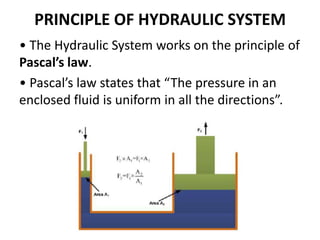


The document provides an overview of hydraulic control systems. It discusses the key components including prime movers, pumps, control valves, actuators, hydraulic fluid, and filters. It explains that hydraulic systems use incompressible fluids to transmit power through a network of components. Common applications include industrial machinery, mobile equipment, automobiles, marine vessels, and aerospace systems.