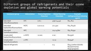
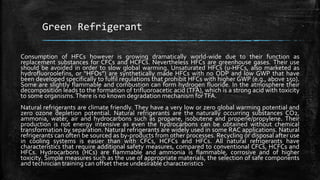
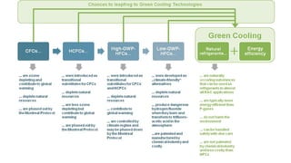
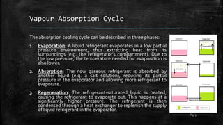
Index
▪ Method of Refrigeration
▪ Vapour Compression Cycle
▪ Refrigerants and their
environmental issues
▪ Green Refrigerant
▪ Vapour Absorption Cycle
– Ammonia Absorption
Refrigeration Cycle
– Einstein Refrigerator
▪ Gas Refrigeration Cycle
▪ Thermoelectric cooling
▪ Magnetic refrigeration
▪ Thermo-acoustic heat engine
▪ Solar Refrigeration
▪ VortexTube
▪ Stirling Cycle
What is Refrigeration?
▪ Refrigeration is a process in which work is done to move heat from one location to
another. The work of heat transport is traditionally driven by mechanical work, but can
also be driven by heat, magnetism, electricity, laser, or other means. Refrigeration has
many applications, including, but not limited to: household refrigerators, industrial
freezers, cryogenics, and air conditioning. Heat pumps may use the heat output of the
refrigeration process, and also may be designed to be reversible, but are otherwise
similar to refrigeration units.
▪ Refrigeration has had a large impact on industry, lifestyle, agriculture and settlement
patterns. However, refrigeration technology has rapidly evolved in the last century,
from ice harvesting to temperature-controlled rail cars. The introduction of refrigerated
rail cars contributed to the westward expansion of the United States, allowing
settlement in areas that were not on main transport channels such as rivers, harbours,
or valley trails. Settlements were also popping up in infertile parts of the country, filled
with new natural resources. In most developed countries, cities are heavily dependent
upon refrigeration in supermarkets, in order to obtain their food for daily consumption.
The increase in food sources has led to a larger concentration of agricultural sales
coming from a smaller percentage of existing farms. This has resulted in new food
sources available to entire populations, which has had a large impact on the nutrition of
society.
Method of Refrigeration
▪ Vapour Cycle
– Vapour Compression Cycle
– VapourAbsorption Cycle
▪ Gas Cycle
▪ Thermoelectric Refrigeration
▪ Magnetic Refrigeration
▪ Solar Refrigeration
▪ VortexTube
▪ Thermo-acoustic Refrigeration
▪ Stirling Cycle
Vapour Compression Cycle
The vapour-compression cycle is used in most household
refrigerators as well as in many large commercial and
industrial refrigeration systems.
In this cycle, a circulating refrigerant enters the compressor
as vapour. From point 1 to point 2, the vapour is compressed
at constant entropy and exits as a vapour at a higher
pressure, but still below the vapour pressure at that
temperature. From point 2 to point 3, the vapour travels
through the condenser which cools the vapour until it starts
condensing by removing additional heat at constant
pressure. Between points 3 and 4, the liquid refrigerant goes
through the expansion valve where its pressure abruptly
decreases, causing flash evaporation and auto-refrigeration
of the liquid. That results in a mixture of liquid and vapour at a
lower temperature at point 4. The cold liquid-vapour mixture
then travels through the evaporator tubes and is completely
vaporized by cooling the warm air (from the space being
refrigerated). The resulting refrigerant vapour returns to the
compressor inlet at point 1 to complete the thermodynamic
cycle.
Fig. 1
What is Refrigerant?
▪ Refrigerants are substances that can be used in the refrigeration cycle of air
conditioning and refrigeration equipment because of their thermodynamic
properties. In most cycles it undergoes phase transitions from a liquid to a
gas and back again. Fluorocarbons, especially chlorofluorocarbons, became
commonplace in the 20th century. Other refrigerants used in various
applications are ammonia, sulphur dioxide, and non-halogenated
hydrocarbons such as propane.
▪ The ideal refrigerant would have favourable thermodynamic properties, be
noncorrosive to mechanical components, and be safe, including free from
toxicity and flammability. The desired thermodynamic properties are a
boiling point somewhat below the target temperature, a high heat of
vaporization, a moderate density in liquid form, a relatively high density in
gaseous form, and a high critical temperature.
Refrigerant environmental issues
The inert nature of many halogens,
chlorofluorocarbons (CFC) and
hydrochlorofluorocarbons (HCFC), with the
benefits of their being non-flammable and
nontoxic, made them good choices as
refrigerants, but their stability in the
atmosphere and their corresponding global
warming potential and ozone depletion
potential raised concerns about their usage.
CFCs and HCFCs are being phased out under
the Montreal Protocol, an international
agreement to protect the ozone layer.They
have been controlled by the Montreal Protocol
since 1987 because of their ozone depleting
potential and high global warming potentials.
Fig. 2
Different groups of refrigerants and their ozone
depletion and global warming potentials
Substance group Abbreviation Ozone Depletion
Potential
GlobalWarming
Potentials
Example
(refrigerant/foam blowing
agent)
Saturated
chlorofluorocarbons
CFC 0.6-1 4750-14,440 R11, R12
Saturated
hydrochlorofluorocarbons
HCFC 0.02-0.11 77-2,310 R22, R141b
Saturated
hydrofluorocarbons
HFC - 124-14,800 R32, R134a
Unsaturated
hydrochlorofluorcarbons
u-HCFC <0.001 0-10 R1233zd
Unsaturated
hydrofluorocarbons
u-HFC - <1-12 R1234yf
Natural refrigerants - - 0-3 R744 (carbon dioxide)
R717(ammonia)
R290 (propane)
Green Refrigerant
Consumption of HFCs however is growing dramatically world-wide due to their function as
replacement substances for CFCs and HCFCs. Nevertheless HFCs are greenhouse gases. Their use
should be avoided in order to slow global warming. Unsaturated HFCs (u-HFCs, also marketed as
hydrofluoroolefins, or “HFOs”) are synthetically made HFCs with no ODP and low GWP that have
been developed specifically to fulfil regulations that prohibit HFCs with higher GWP (e.g., above 150).
Some are slightly flammable and combustion can form hydrogen fluoride. In the atmosphere their
decomposition leads to the formation of trifluoroacetic acid (TFA), which is a strong acid with toxicity
to some organisms.There is no known degradation mechanism forTFA.
Natural refrigerants are climate friendly. They have a very low or zero global warming potential and
zero ozone depletion potential. Natural refrigerants are the naturally occurring substances CO2,
ammonia, water, air and hydrocarbons such as propane, isobutene and propene/propylene. Their
production is not energy intensive as even the hydrocarbons can be obtained without chemical
transformation by separation. Natural refrigerants are widely used in some RAC applications. Natural
refrigerants can often be sourced as by-products from other processes. Recycling or disposal after use
in cooling systems is easier than with CFCs, HCFCs and HFCs. All natural refrigerants have
characteristics that require additional safety measures, compared to conventional CFCs, HCFCs and
HFCs. Hydrocarbons (HCs) are flammable and ammonia is flammable, corrosive and of higher
toxicity. Simple measures such as the use of appropriate materials, the selection of safe components
and technician training can offset these undesirable characteristics
Vapour Absorption Cycle
The absorption cooling cycle can be described in three phases:
1. Evaporation: A liquid refrigerant evaporates in a low partial
pressure environment, thus extracting heat from its
surroundings (e.g. the refrigerator's compartment). Due to
the low pressure, the temperature needed for evaporation is
also lower.
2. Absorption: The now gaseous refrigerant is absorbed by
another liquid (e.g. a salt solution), reducing its partial
pressure in the evaporator and allowing more refrigerant to
evaporate.
3. Regeneration: The refrigerant-saturated liquid is heated,
causing the refrigerant to evaporate out. This happens at a
significantly higher pressure. The refrigerant is then
condensed through a heat exchanger to replenish the supply
of liquid refrigerant in the evaporator.
Fig. 3
Ammonia Absorption Refrigeration Cycle- an
Example of Vapour Absorption Cycle
▪ Ammonia vapour is vigorously absorbed in water. So when
low-pressure ammonia vapour from the evaporator comes in
contact in the absorber with weak solution coming from
generator is readily absorbed, by releasing latent heat of
condensation. The temperature of the solution rises, while
absorber gets cooled.
▪ Now the absorber is pumped to generator through heat-
exchanger. In generator some heat is being added and hence
by rectifying fresh gas is sent to condenser and solution to
absorber through heat-exchanger.
▪ Now fresh gas is condensed into condenser. And the
condensed liquid is sent to evaporator through heat-
exchanger & expansion valve.
▪ In evaporator liquid evaporates by taking latent heat of
evaporation from the sink. And the evaporated liquid is sent
to absorber through heat-exchanger.
Fig. 4
Einstein refrigerator
▪ The Einstein–Szilard or Einstein refrigerator is an absorption refrigerator which
has no moving parts, operates at constant pressure, and requires only a heat
source to operate. It was jointly invented in 1926 by Albert Einstein and his
former student Leó Szilárd.
▪ The machine is a single pressure absorption refrigerator, similar in design to a
gas absorption refrigerator. The refrigeration cycle uses ammonia pressure
equalizing fluid, butane refrigerant, and water absorbing fluid, has no moving
parts, and does not require electricity to operate, needing only a heat source,
e.g. a small gas burner or electric heating element or even solar energy.
▪ On the cold side of a conventional refrigerator, a refrigerant evaporates at a
temperature dependent pressure, 𝑃𝑟𝑒𝑓(𝑇𝑙𝑜𝑤). Evaporation absorbs heat from
whatever is being cooled, and the vapor flows to a compressor. In an equivalent
Einstein refrigerator, the refrigerant liquid evaporates at what is now a partial
pressure 𝑃𝑟𝑒𝑓(𝑇𝑙𝑜𝑤) mixing with a flow of ammonia vapor to form a gas with a
total pressure near the system pressure: 𝑃𝑟𝑒𝑓+ 𝑃𝑎𝑚𝑛 = 𝑃𝑠𝑦𝑠. The mixture flows,
not to a pump, but to an ammonia absorber.
Einstein refrigerator
▪ On the hot side of a conventional refrigerator, a compressor raises the pressure
of the refrigerant vapor, enabling it to condense at a relatively high temperature
to deliver heat to an external heat exchanger. On the hot side of a Einstein
refrigerator, an ammonia absorber raises the partial pressure of the refrigerant
vapor to accomplish the same result. The absorber works by removing ammonia
vapor by dissolving it in water.
▪ The absorber works by removing ammonia vapor by dissolving it in water. As
this happens, the gas mixture flows to maintain the nearly constant pressure
𝑃𝑠𝑦𝑠, and as a consequence, the partial pressure of the refrigerant, 𝑃𝑟𝑒𝑓, can
approach 𝑃𝑠𝑦𝑠. At this higher partial pressure, it can condense and deliver heat to
an external heat convector, as in a conventional refrigerator.
▪ The condensed refrigerant liquid cannot dissolve in water and, in the case of
butane, it will float, making it easy to separate and return to the evaporator.
Meanwhile, the ammonia/water solution flows to an ammonia generator, where
the heat source that powers the refrigerator raises the temperature of the
solution, driving out the ammonia and providing the ammonia vapor that is the
other input to the evaporator.This is the operating principle of the system.
Fig. 5
Gas Cycle
▪ When the working fluid is a gas that is compressed and
expanded but doesn't change phase, the refrigeration
cycle is called a gas cycle. Air is most often this working
fluid. As there is no condensation and evaporation
intended in a gas cycle, components corresponding to
the condenser and evaporator in a vapour compression
cycle are the hot and cold gas-to-gas heat exchangers
in gas cycles.
▪ The gas cycle is less efficient than the vapour
compression cycle because the gas cycle works on the
reverse Brayton cycle instead of the reverse Rankine
cycle. As such the working fluid does not receive and
reject heat at constant temperature. In the gas cycle,
the refrigeration effect is equal to the product of the
specific heat of the gas and the rise in temperature of
the gas in the low temperature side. Therefore, for the
same cooling load, a gas refrigeration cycle needs a
large mass flow rate and is bulky.
Fig. 6
Thermoelectric cooling
Thermoelectric coolers operate by the Peltier effect (which also goes by
the more general name thermoelectric effect). The device has two
sides, and when DC current flows through the device, it brings heat
from one side to the other, so that one side gets cooler while the other
gets hotter. The "hot" side is attached to a heat sink so that it remains at
ambient temperature, while the cool side goes below room
temperature. In some applications, multiple coolers can be cascaded
together for lower temperature.
Two unique semiconductors, one n-type and one p-type, are used
because they need to have different electron densities. The
semiconductors are placed thermally in parallel to each other and
electrically in series and then joined with a thermally conducting plate
on each side. When a voltage is applied to the free ends of the two
semiconductors there is a flow of DC current across the junction of the
semiconductors causing a temperature difference. The side with the
cooling plate absorbs heat which is then moved to the other side of the
device where the heat sink is. TECs are typically connected side by side
and sandwiched between two ceramic plates. The cooling ability of the
total unit is then proportional to the number ofTECs in it
Fig. 7
Fig. 8
Magnetic refrigeration
Magnetic refrigeration is a cooling technology based on the magneto caloric effect.
Compared to traditional gas-compression refrigeration, magnetic refrigeration is
safer and more environmentally friendly because it does not use harmful, ozone-
depleting coolant gases, quieter, more compact, and has a higher cooling efficiency.
The magneto caloric effect is a magneto-thermodynamic phenomenon in which a
temperature change of suitable material is caused by exposing the material to a
changing magnetic field.
In that part of the refrigeration process, a decrease in the strength of an externally
applied magnetic field allows the magnetic domains of a magneto caloric material
to become disoriented from the magnetic field by the agitating action of the
thermal energy (phonons) present in the material. If the material is isolated so that
no energy is allowed to (re)migrate into the material during this time, (i.e., an
adiabatic process) the temperature drops as the domains absorb the thermal
energy to perform their reorientation.
First, a strong magnetic field is applied to the refrigerant, forcing its various
magnetic dipoles to align and putting these degrees of freedom of the refrigerant
into a state of lowered entropy. The heat sink then absorbs the heat released by the
refrigerant due to its loss of entropy. Thermal contact with the heat sink is then
broken so that the system is insulated, and the magnetic field is switched off,
increasing the heat capacity of the refrigerant, thus decreasing its temperature
below the temperature of the heat sink.
Fig. 9
Thermo-acoustic heat engine
▪ Thermo acoustic engines (sometimes called "TA engines") are thermo
acoustic devices which use high-amplitude sound waves to pump heat from one
place to another. Compared to vapor refrigerators, thermoacoustic refrigerators
have no ozone-depleting or toxic coolant and few or no moving parts therefore
require no dynamic sealing or lubrication.
▪ A thermoacoustic device basically consists of heat exchangers, a resonator, and
a stack (on standing wave devices) orregenerator (on travelling wave devices).
Depending on the type of engine a driver or loudspeaker might be used as well
to generate sound waves.
▪ Acoustic waves experience displacement oscillations, and temperature
oscillation in association with pressure variations.in order to produce thermo
acoustic effect, these oscillation in the gas should occur close to a solid surface,
so that heat is transferred to and from the surface. A stack of closely placed
parallel plates is placed in the thermo acoustic device in order to provide such a
solid surface. The thermo acoustic phenomenon occurs by the interaction of the
gas particles and the stack plate. When large temperature gradients are created
across the stack, sound waves are generated. In the reverse case, the acoustic
work in order to create temperature gradient across the stack, which is used to
transfer heat from a low temperature medium to a high temperature medium.
Fig. 10
Solar Refrigeration
▪ Refrigerator that runs on electricity
provided by solar energy are called solar
refrigeration. These type of solar
refrigeration can minimize the harmful
impact on environment as well as the
cost of fuel.
▪ There are three types of solar
refrigeration systems: photovoltaic
operated refrigeration cycle, solar
mechanical refrigeration and absorption
refrigeration.
▪ Solar refrigerators are environmental
friendly and beneficial in terms of
longevity and scalability.
▪ Their disadvantages are that their COP is
low, bulky arrangement and high initial
investment.
Vortex Tube
▪ The vortex tube is a mechanical device that separates a compressed gas into hot
and cold streams. The air emerging from the "hot" end can reach temperatures of
200 °C, and the air emerging from the "cold end" can reach -50 °C. It has no moving
parts. Pressurized gas is injected tangentially into a swirl chamber and accelerated
to a high rate of rotation. Due to the conical nozzle at the end of the tube, only the
outer shell of the compressed gas is allowed to escape at that end. The remainder of
the gas is forced to return in an inner vortex of reduced diameter within the outer
vortex.
▪ The main physical phenomenon of the vortex tube is the temperature separation
between the cold vortex core and the warm vortex periphery. Under this
fundamental approach, this is explained with the work equation of Euler, also
known as Euler's turbine equation, which can be written in its most general vector
form as:
▪ 𝑇 −
𝑣⋅⍵ × 𝑟
𝐶 𝑝
= constant
▪ where T is the total, or stagnation temperature of the rotating gas at radial position
𝑟, the absolute gas velocity as observed from the stationary frame of reference is
denoted with 𝑣; the angular velocity of the system is ⍵ and 𝐶 𝑝 is the isobaric heat
capacity of the gas. The above equation is valid for an adiabatic turbine passage; it
clearly shows that while gas moving towards the centre is becoming colder the
peripheral gas in the passage is becoming faster. Therefore, vortex cooling is due to
angular propulsion. The more the gas cools by reaching the centre, the more
rotational energy it delivers to the vortex and it rotates even faster
Fig. 15
Stirling cycle
▪ The Stirling cycle is a thermodynamic cycle that was invented, developed and
patented in 1816 by Reverend Dr. Robert Stirling with help from his brother, an
engineer.The Stirling cycle is an altered version of the Carnot cycle in which the
two isentropic processes featured in the Carnot cycle are replaced by two
constant-volume regeneration processes.The cycle is the same as most other
heat cycles in that there are four main processes: Isothermal expansion.The
expansion space is heated externally, and the gas undergoes near-isothermal
expansion.
1. Isothermal expansion:The expansion space is heated externally, and the gas
undergoes near-isothermal expansion
2. Constant-volume heat removal:The gas is passed through the regenerator,
thus cooling the gas, and transferring heat to the regenerator for use in the
next cycle.
3. Isothermal compression:The compression space is intercooled, so the gas
undergoes near-isothermal compression.
4. Constant-volume heat addition:The compressed air flows back through the
regenerator and picks up heat on the way to the heated expansion space.
Fig. 16
Fig. 17
References and Links
▪ Notes: EngineeringThermodynamics by P.K. Nag
EngineeringThermodynamics by Cengel and Boles
 External Links: http://en.wikipedia.org/wiki/Einstein_refrigerator
http://www.slideshare.net/devakumar21/solar-
refrigeration-36746340
http://en.wikipedia.org/wiki/Magnetic_refrigeration
http://en.wikipedia.org/wiki/Thermoacoustic_heat_engine
Acknowledgement
This project consumed dedication, hard work and sincerity. Still
implementation wouldn’t have been possible if we didn’t have the
support of many individuals. We want to take this opportunity to
extend our sincere thanks to Prof. Amitabha Dutta, Prof. Ashok
Kumar Santra and Mr. Mithun Das who devoted their time and
knowledge for the implementation of our lab works.
Green refrigeration

Green refrigeration

  • 2.
    Index ▪ Method ofRefrigeration ▪ Vapour Compression Cycle ▪ Refrigerants and their environmental issues ▪ Green Refrigerant ▪ Vapour Absorption Cycle – Ammonia Absorption Refrigeration Cycle – Einstein Refrigerator ▪ Gas Refrigeration Cycle ▪ Thermoelectric cooling ▪ Magnetic refrigeration ▪ Thermo-acoustic heat engine ▪ Solar Refrigeration ▪ VortexTube ▪ Stirling Cycle
  • 3.
    What is Refrigeration? ▪Refrigeration is a process in which work is done to move heat from one location to another. The work of heat transport is traditionally driven by mechanical work, but can also be driven by heat, magnetism, electricity, laser, or other means. Refrigeration has many applications, including, but not limited to: household refrigerators, industrial freezers, cryogenics, and air conditioning. Heat pumps may use the heat output of the refrigeration process, and also may be designed to be reversible, but are otherwise similar to refrigeration units. ▪ Refrigeration has had a large impact on industry, lifestyle, agriculture and settlement patterns. However, refrigeration technology has rapidly evolved in the last century, from ice harvesting to temperature-controlled rail cars. The introduction of refrigerated rail cars contributed to the westward expansion of the United States, allowing settlement in areas that were not on main transport channels such as rivers, harbours, or valley trails. Settlements were also popping up in infertile parts of the country, filled with new natural resources. In most developed countries, cities are heavily dependent upon refrigeration in supermarkets, in order to obtain their food for daily consumption. The increase in food sources has led to a larger concentration of agricultural sales coming from a smaller percentage of existing farms. This has resulted in new food sources available to entire populations, which has had a large impact on the nutrition of society.
  • 4.
    Method of Refrigeration ▪Vapour Cycle – Vapour Compression Cycle – VapourAbsorption Cycle ▪ Gas Cycle ▪ Thermoelectric Refrigeration ▪ Magnetic Refrigeration ▪ Solar Refrigeration ▪ VortexTube ▪ Thermo-acoustic Refrigeration ▪ Stirling Cycle
  • 5.
    Vapour Compression Cycle Thevapour-compression cycle is used in most household refrigerators as well as in many large commercial and industrial refrigeration systems. In this cycle, a circulating refrigerant enters the compressor as vapour. From point 1 to point 2, the vapour is compressed at constant entropy and exits as a vapour at a higher pressure, but still below the vapour pressure at that temperature. From point 2 to point 3, the vapour travels through the condenser which cools the vapour until it starts condensing by removing additional heat at constant pressure. Between points 3 and 4, the liquid refrigerant goes through the expansion valve where its pressure abruptly decreases, causing flash evaporation and auto-refrigeration of the liquid. That results in a mixture of liquid and vapour at a lower temperature at point 4. The cold liquid-vapour mixture then travels through the evaporator tubes and is completely vaporized by cooling the warm air (from the space being refrigerated). The resulting refrigerant vapour returns to the compressor inlet at point 1 to complete the thermodynamic cycle. Fig. 1
  • 6.
    What is Refrigerant? ▪Refrigerants are substances that can be used in the refrigeration cycle of air conditioning and refrigeration equipment because of their thermodynamic properties. In most cycles it undergoes phase transitions from a liquid to a gas and back again. Fluorocarbons, especially chlorofluorocarbons, became commonplace in the 20th century. Other refrigerants used in various applications are ammonia, sulphur dioxide, and non-halogenated hydrocarbons such as propane. ▪ The ideal refrigerant would have favourable thermodynamic properties, be noncorrosive to mechanical components, and be safe, including free from toxicity and flammability. The desired thermodynamic properties are a boiling point somewhat below the target temperature, a high heat of vaporization, a moderate density in liquid form, a relatively high density in gaseous form, and a high critical temperature.
  • 7.
    Refrigerant environmental issues Theinert nature of many halogens, chlorofluorocarbons (CFC) and hydrochlorofluorocarbons (HCFC), with the benefits of their being non-flammable and nontoxic, made them good choices as refrigerants, but their stability in the atmosphere and their corresponding global warming potential and ozone depletion potential raised concerns about their usage. CFCs and HCFCs are being phased out under the Montreal Protocol, an international agreement to protect the ozone layer.They have been controlled by the Montreal Protocol since 1987 because of their ozone depleting potential and high global warming potentials. Fig. 2
  • 9.
    Different groups ofrefrigerants and their ozone depletion and global warming potentials Substance group Abbreviation Ozone Depletion Potential GlobalWarming Potentials Example (refrigerant/foam blowing agent) Saturated chlorofluorocarbons CFC 0.6-1 4750-14,440 R11, R12 Saturated hydrochlorofluorocarbons HCFC 0.02-0.11 77-2,310 R22, R141b Saturated hydrofluorocarbons HFC - 124-14,800 R32, R134a Unsaturated hydrochlorofluorcarbons u-HCFC <0.001 0-10 R1233zd Unsaturated hydrofluorocarbons u-HFC - <1-12 R1234yf Natural refrigerants - - 0-3 R744 (carbon dioxide) R717(ammonia) R290 (propane)
  • 10.
    Green Refrigerant Consumption ofHFCs however is growing dramatically world-wide due to their function as replacement substances for CFCs and HCFCs. Nevertheless HFCs are greenhouse gases. Their use should be avoided in order to slow global warming. Unsaturated HFCs (u-HFCs, also marketed as hydrofluoroolefins, or “HFOs”) are synthetically made HFCs with no ODP and low GWP that have been developed specifically to fulfil regulations that prohibit HFCs with higher GWP (e.g., above 150). Some are slightly flammable and combustion can form hydrogen fluoride. In the atmosphere their decomposition leads to the formation of trifluoroacetic acid (TFA), which is a strong acid with toxicity to some organisms.There is no known degradation mechanism forTFA. Natural refrigerants are climate friendly. They have a very low or zero global warming potential and zero ozone depletion potential. Natural refrigerants are the naturally occurring substances CO2, ammonia, water, air and hydrocarbons such as propane, isobutene and propene/propylene. Their production is not energy intensive as even the hydrocarbons can be obtained without chemical transformation by separation. Natural refrigerants are widely used in some RAC applications. Natural refrigerants can often be sourced as by-products from other processes. Recycling or disposal after use in cooling systems is easier than with CFCs, HCFCs and HFCs. All natural refrigerants have characteristics that require additional safety measures, compared to conventional CFCs, HCFCs and HFCs. Hydrocarbons (HCs) are flammable and ammonia is flammable, corrosive and of higher toxicity. Simple measures such as the use of appropriate materials, the selection of safe components and technician training can offset these undesirable characteristics
  • 12.
    Vapour Absorption Cycle Theabsorption cooling cycle can be described in three phases: 1. Evaporation: A liquid refrigerant evaporates in a low partial pressure environment, thus extracting heat from its surroundings (e.g. the refrigerator's compartment). Due to the low pressure, the temperature needed for evaporation is also lower. 2. Absorption: The now gaseous refrigerant is absorbed by another liquid (e.g. a salt solution), reducing its partial pressure in the evaporator and allowing more refrigerant to evaporate. 3. Regeneration: The refrigerant-saturated liquid is heated, causing the refrigerant to evaporate out. This happens at a significantly higher pressure. The refrigerant is then condensed through a heat exchanger to replenish the supply of liquid refrigerant in the evaporator. Fig. 3
  • 13.
    Ammonia Absorption RefrigerationCycle- an Example of Vapour Absorption Cycle ▪ Ammonia vapour is vigorously absorbed in water. So when low-pressure ammonia vapour from the evaporator comes in contact in the absorber with weak solution coming from generator is readily absorbed, by releasing latent heat of condensation. The temperature of the solution rises, while absorber gets cooled. ▪ Now the absorber is pumped to generator through heat- exchanger. In generator some heat is being added and hence by rectifying fresh gas is sent to condenser and solution to absorber through heat-exchanger. ▪ Now fresh gas is condensed into condenser. And the condensed liquid is sent to evaporator through heat- exchanger & expansion valve. ▪ In evaporator liquid evaporates by taking latent heat of evaporation from the sink. And the evaporated liquid is sent to absorber through heat-exchanger. Fig. 4
  • 14.
    Einstein refrigerator ▪ TheEinstein–Szilard or Einstein refrigerator is an absorption refrigerator which has no moving parts, operates at constant pressure, and requires only a heat source to operate. It was jointly invented in 1926 by Albert Einstein and his former student Leó Szilárd. ▪ The machine is a single pressure absorption refrigerator, similar in design to a gas absorption refrigerator. The refrigeration cycle uses ammonia pressure equalizing fluid, butane refrigerant, and water absorbing fluid, has no moving parts, and does not require electricity to operate, needing only a heat source, e.g. a small gas burner or electric heating element or even solar energy. ▪ On the cold side of a conventional refrigerator, a refrigerant evaporates at a temperature dependent pressure, 𝑃𝑟𝑒𝑓(𝑇𝑙𝑜𝑤). Evaporation absorbs heat from whatever is being cooled, and the vapor flows to a compressor. In an equivalent Einstein refrigerator, the refrigerant liquid evaporates at what is now a partial pressure 𝑃𝑟𝑒𝑓(𝑇𝑙𝑜𝑤) mixing with a flow of ammonia vapor to form a gas with a total pressure near the system pressure: 𝑃𝑟𝑒𝑓+ 𝑃𝑎𝑚𝑛 = 𝑃𝑠𝑦𝑠. The mixture flows, not to a pump, but to an ammonia absorber.
  • 15.
    Einstein refrigerator ▪ Onthe hot side of a conventional refrigerator, a compressor raises the pressure of the refrigerant vapor, enabling it to condense at a relatively high temperature to deliver heat to an external heat exchanger. On the hot side of a Einstein refrigerator, an ammonia absorber raises the partial pressure of the refrigerant vapor to accomplish the same result. The absorber works by removing ammonia vapor by dissolving it in water. ▪ The absorber works by removing ammonia vapor by dissolving it in water. As this happens, the gas mixture flows to maintain the nearly constant pressure 𝑃𝑠𝑦𝑠, and as a consequence, the partial pressure of the refrigerant, 𝑃𝑟𝑒𝑓, can approach 𝑃𝑠𝑦𝑠. At this higher partial pressure, it can condense and deliver heat to an external heat convector, as in a conventional refrigerator. ▪ The condensed refrigerant liquid cannot dissolve in water and, in the case of butane, it will float, making it easy to separate and return to the evaporator. Meanwhile, the ammonia/water solution flows to an ammonia generator, where the heat source that powers the refrigerator raises the temperature of the solution, driving out the ammonia and providing the ammonia vapor that is the other input to the evaporator.This is the operating principle of the system. Fig. 5
  • 16.
    Gas Cycle ▪ Whenthe working fluid is a gas that is compressed and expanded but doesn't change phase, the refrigeration cycle is called a gas cycle. Air is most often this working fluid. As there is no condensation and evaporation intended in a gas cycle, components corresponding to the condenser and evaporator in a vapour compression cycle are the hot and cold gas-to-gas heat exchangers in gas cycles. ▪ The gas cycle is less efficient than the vapour compression cycle because the gas cycle works on the reverse Brayton cycle instead of the reverse Rankine cycle. As such the working fluid does not receive and reject heat at constant temperature. In the gas cycle, the refrigeration effect is equal to the product of the specific heat of the gas and the rise in temperature of the gas in the low temperature side. Therefore, for the same cooling load, a gas refrigeration cycle needs a large mass flow rate and is bulky. Fig. 6
  • 17.
    Thermoelectric cooling Thermoelectric coolersoperate by the Peltier effect (which also goes by the more general name thermoelectric effect). The device has two sides, and when DC current flows through the device, it brings heat from one side to the other, so that one side gets cooler while the other gets hotter. The "hot" side is attached to a heat sink so that it remains at ambient temperature, while the cool side goes below room temperature. In some applications, multiple coolers can be cascaded together for lower temperature. Two unique semiconductors, one n-type and one p-type, are used because they need to have different electron densities. The semiconductors are placed thermally in parallel to each other and electrically in series and then joined with a thermally conducting plate on each side. When a voltage is applied to the free ends of the two semiconductors there is a flow of DC current across the junction of the semiconductors causing a temperature difference. The side with the cooling plate absorbs heat which is then moved to the other side of the device where the heat sink is. TECs are typically connected side by side and sandwiched between two ceramic plates. The cooling ability of the total unit is then proportional to the number ofTECs in it Fig. 7 Fig. 8
  • 18.
    Magnetic refrigeration Magnetic refrigerationis a cooling technology based on the magneto caloric effect. Compared to traditional gas-compression refrigeration, magnetic refrigeration is safer and more environmentally friendly because it does not use harmful, ozone- depleting coolant gases, quieter, more compact, and has a higher cooling efficiency. The magneto caloric effect is a magneto-thermodynamic phenomenon in which a temperature change of suitable material is caused by exposing the material to a changing magnetic field. In that part of the refrigeration process, a decrease in the strength of an externally applied magnetic field allows the magnetic domains of a magneto caloric material to become disoriented from the magnetic field by the agitating action of the thermal energy (phonons) present in the material. If the material is isolated so that no energy is allowed to (re)migrate into the material during this time, (i.e., an adiabatic process) the temperature drops as the domains absorb the thermal energy to perform their reorientation. First, a strong magnetic field is applied to the refrigerant, forcing its various magnetic dipoles to align and putting these degrees of freedom of the refrigerant into a state of lowered entropy. The heat sink then absorbs the heat released by the refrigerant due to its loss of entropy. Thermal contact with the heat sink is then broken so that the system is insulated, and the magnetic field is switched off, increasing the heat capacity of the refrigerant, thus decreasing its temperature below the temperature of the heat sink. Fig. 9
  • 19.
    Thermo-acoustic heat engine ▪Thermo acoustic engines (sometimes called "TA engines") are thermo acoustic devices which use high-amplitude sound waves to pump heat from one place to another. Compared to vapor refrigerators, thermoacoustic refrigerators have no ozone-depleting or toxic coolant and few or no moving parts therefore require no dynamic sealing or lubrication. ▪ A thermoacoustic device basically consists of heat exchangers, a resonator, and a stack (on standing wave devices) orregenerator (on travelling wave devices). Depending on the type of engine a driver or loudspeaker might be used as well to generate sound waves. ▪ Acoustic waves experience displacement oscillations, and temperature oscillation in association with pressure variations.in order to produce thermo acoustic effect, these oscillation in the gas should occur close to a solid surface, so that heat is transferred to and from the surface. A stack of closely placed parallel plates is placed in the thermo acoustic device in order to provide such a solid surface. The thermo acoustic phenomenon occurs by the interaction of the gas particles and the stack plate. When large temperature gradients are created across the stack, sound waves are generated. In the reverse case, the acoustic work in order to create temperature gradient across the stack, which is used to transfer heat from a low temperature medium to a high temperature medium. Fig. 10
  • 20.
    Solar Refrigeration ▪ Refrigeratorthat runs on electricity provided by solar energy are called solar refrigeration. These type of solar refrigeration can minimize the harmful impact on environment as well as the cost of fuel. ▪ There are three types of solar refrigeration systems: photovoltaic operated refrigeration cycle, solar mechanical refrigeration and absorption refrigeration. ▪ Solar refrigerators are environmental friendly and beneficial in terms of longevity and scalability. ▪ Their disadvantages are that their COP is low, bulky arrangement and high initial investment.
  • 21.
    Vortex Tube ▪ Thevortex tube is a mechanical device that separates a compressed gas into hot and cold streams. The air emerging from the "hot" end can reach temperatures of 200 °C, and the air emerging from the "cold end" can reach -50 °C. It has no moving parts. Pressurized gas is injected tangentially into a swirl chamber and accelerated to a high rate of rotation. Due to the conical nozzle at the end of the tube, only the outer shell of the compressed gas is allowed to escape at that end. The remainder of the gas is forced to return in an inner vortex of reduced diameter within the outer vortex. ▪ The main physical phenomenon of the vortex tube is the temperature separation between the cold vortex core and the warm vortex periphery. Under this fundamental approach, this is explained with the work equation of Euler, also known as Euler's turbine equation, which can be written in its most general vector form as: ▪ 𝑇 − 𝑣⋅⍵ × 𝑟 𝐶 𝑝 = constant ▪ where T is the total, or stagnation temperature of the rotating gas at radial position 𝑟, the absolute gas velocity as observed from the stationary frame of reference is denoted with 𝑣; the angular velocity of the system is ⍵ and 𝐶 𝑝 is the isobaric heat capacity of the gas. The above equation is valid for an adiabatic turbine passage; it clearly shows that while gas moving towards the centre is becoming colder the peripheral gas in the passage is becoming faster. Therefore, vortex cooling is due to angular propulsion. The more the gas cools by reaching the centre, the more rotational energy it delivers to the vortex and it rotates even faster Fig. 15
  • 22.
    Stirling cycle ▪ TheStirling cycle is a thermodynamic cycle that was invented, developed and patented in 1816 by Reverend Dr. Robert Stirling with help from his brother, an engineer.The Stirling cycle is an altered version of the Carnot cycle in which the two isentropic processes featured in the Carnot cycle are replaced by two constant-volume regeneration processes.The cycle is the same as most other heat cycles in that there are four main processes: Isothermal expansion.The expansion space is heated externally, and the gas undergoes near-isothermal expansion. 1. Isothermal expansion:The expansion space is heated externally, and the gas undergoes near-isothermal expansion 2. Constant-volume heat removal:The gas is passed through the regenerator, thus cooling the gas, and transferring heat to the regenerator for use in the next cycle. 3. Isothermal compression:The compression space is intercooled, so the gas undergoes near-isothermal compression. 4. Constant-volume heat addition:The compressed air flows back through the regenerator and picks up heat on the way to the heated expansion space. Fig. 16 Fig. 17
  • 23.
    References and Links ▪Notes: EngineeringThermodynamics by P.K. Nag EngineeringThermodynamics by Cengel and Boles  External Links: http://en.wikipedia.org/wiki/Einstein_refrigerator http://www.slideshare.net/devakumar21/solar- refrigeration-36746340 http://en.wikipedia.org/wiki/Magnetic_refrigeration http://en.wikipedia.org/wiki/Thermoacoustic_heat_engine
  • 24.
    Acknowledgement This project consumeddedication, hard work and sincerity. Still implementation wouldn’t have been possible if we didn’t have the support of many individuals. We want to take this opportunity to extend our sincere thanks to Prof. Amitabha Dutta, Prof. Ashok Kumar Santra and Mr. Mithun Das who devoted their time and knowledge for the implementation of our lab works.