Downloaded 458 times
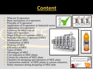
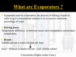
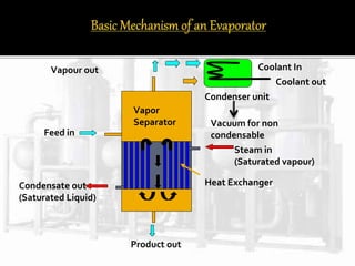
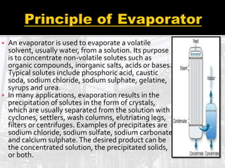
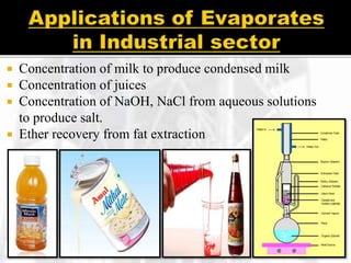
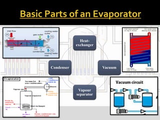
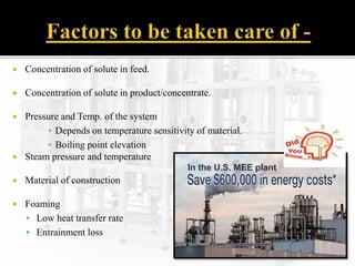
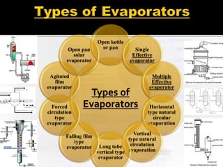
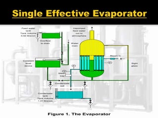
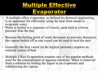
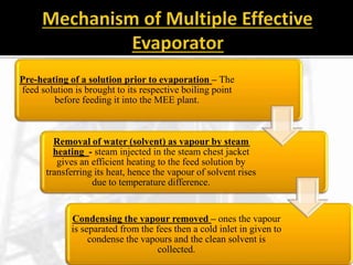
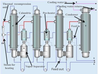
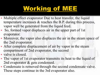
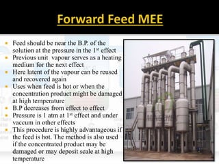
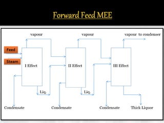
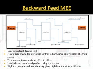
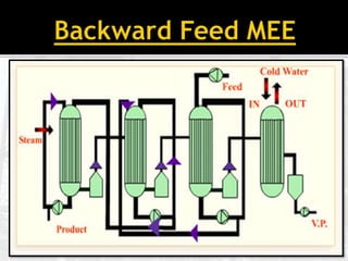
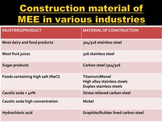
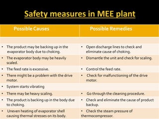


The document presents an extensive overview of evaporators, focusing on their mechanisms, principles, types, and applications within various industrial sectors. It details the functioning of multiple-effect evaporators (MEE), emphasizing their efficiency in concentrating solutions and the necessary operational considerations such as temperature, pressure, and material construction. Additionally, it outlines the challenges and maintenance issues that may arise during the operation of evaporators, along with potential solutions.


![Temperature – limiting factor [autosaved] new](https://cdn.slidesharecdn.com/ss_thumbnails/temperaturelimitingfactorautosavednew-160718170804-thumbnail.jpg?width=640&height=640&fit=bounds)


