Downloaded 273 times


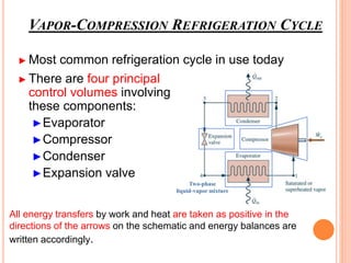
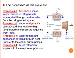
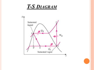
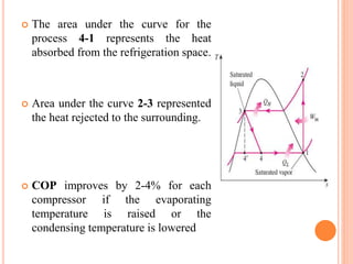
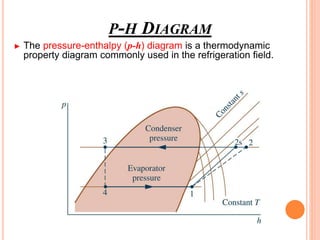


The vapor compression refrigeration cycle involves four main processes: 1) Evaporation and heat absorption in the evaporator 2) Compression of the vapor refrigerant requiring work input in the compressor 3) Condensation of the vapor and heat rejection to the surroundings in the condenser 4) Expansion of the liquid refrigerant through an expansion valve.


![Refregeration & Air Conditioning[1].pptx](https://cdn.slidesharecdn.com/ss_thumbnails/refregerationairconditioning1-251006061651-30262e8a-thumbnail.jpg?width=640&height=640&fit=bounds)