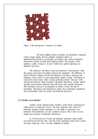
SlideShare a Scribd company logo
1 of 41
1
CHAPTER 1
1. INTRODUCTION TO REFRIGERATION
1.1 What is Refrigeration?
Refrigeration is a process in which work is done to move heat from one
location to another. Refrigeration has many applications, including, but not limited to:
household refrigerators, industrial freezers, cryogenics, air conditioning, and heat pumps.
Refrigeration cools a closed space by removing heat from it. In other words,
refrigeration is a phenomenon by virtue of which the temperature of a body is reduced
compared with the surroundings.
Definition of Refrigeration:
Refrigeration is the process of removal of heat from the confined
(closed) space so as to reduce its temperature below the surrounding
temperature and maintain it at that temperature.
The temperature at which refrigeration is to be produced depends on the
particular application.
1.2 Refrigerators:
Refrigerators work according to the second law of thermodynamics stated by
Clausius:
“It is impossible to construct a device that operates in a cycle and produces no
effect other than the transfer of heat from a body at low temperature to a body at high
temperature without any external aid”
2
Refrigerators are cyclic devices having working substances called refrigerants
used in refrigeration cycles. A refrigerant is a medium of heat transfer, which absorbs heat by
evaporating at low temperatureand gives out heat by condensing at high temperature and
pressure conditions.
Figure 1: Refrigerator
1.3 Measurement of Refrigeration Effect:
The refrigerating effect or capacity is measured in terms of ton of refrigeration or
simply ton denoted by the symbol TR.
Definition of TR:
One TR is equivalent to the production of cold at the rate at which heat
is to be removed from one US tonne of water at 0˚C to freeze it to ice at 0˚C in
24 hours.
1 TR = ((1 × 2000 lb) × 144 Btu / lb)/ 24
= 1200 Btu / h
3
Here, latent heat of fusion of ice has been taken as 144 Btu / lb. In
general, 1 TR is always equal to 12,000 Btu of heat removed per hour
irrespective of the working substance used and its temperature.
Also,
1 TR = 50.4 kcal / min
= 211 kJ / min
= 3.157 kW
=12,660 kJ/h
1.4 Applications of Refrigeration:
The application of refrigeration are numerous in our daily life, some of them are given
below:
(i) Comfort air conditioning of auditoriums, hospitals, residences, hotels, offices
etc.
Probably the most widely used current applications of refrigeration are
for air conditioning of private homes and public buildings,
(ii) Manufacture and preservation of medicines, Surgery has found a wide
application because preservation of blood and human tissue has become
possible by refrigeration only.
(iii) Storage and transportation of food stuffs such as meat, dairy product, fish,
fruit, vegetables and fruit juices etc. The use of refrigerators in kitchens for
storing fruits and vegetables has allowed adding fresh salads to the modern
diet year round, and storing fish and meats safely for long periods.
(iv) Manufacture of ice.
(v) Processing of textiles, printing work and photographic material etc.
(vi) Cooling of concrete for dams.
(vii) Production of rocked fuels.
(viii) Computer functioning
(ix) In commerce and manufacturing, there are many uses for refrigeration.
4
(a) Refrigeration is used to liquify gases - oxygen, nitrogen, propane
and methane, for example.
(b) In compressed air purification, it is used to condense water vapor
from compressed air to reduce its moisture content.
(c) In oil refineries, chemical plants, and petrochemical plants,
refrigeration is used to maintain certain processes at their needed
low temperatures (for example, in alkylation of butenes and butane
to produce a high octane gasoline component).
(d) Metal workers use refrigeration to temper steel and cutlery. In
transporting temperature-sensitive foodstuffs and other materials
by trucks, trains, airplanes and sea-going vessels, refrigeration is a
necessity.
(x) Dairy products are constantly in need of refrigeration, and it was only
discovered in the past few decades that eggs needed to be refrigerated during
shipment rather than waiting to be refrigerated after arrival at the grocery
store. Meats, poultry and fish all must be kept in climate-controlled
environments before being sold. Refrigeration also helps keep fruits and
vegetables edible longer.
1.5 Various methods of refrigeration:
Methods of refrigeration can be classified as non-cyclic, cyclic, thermoelectric
and magnetic.
1.5.1 Non-cyclic refrigeration
(a) In non-cyclic refrigeration, cooling is accomplished by melting ice or by
sublimingdry ice (frozen carbon dioxide). These methods are used for small-
scale refrigeration such as in laboratories and workshops, or in portable
coolers.
Ice owes its effectiveness as a cooling agent to its melting point of 0 °C (32
°F) at sea level. To melt, ice must absorb 333.55 kJ/kg (about 144 Btu/lb) of
heat. Foodstuffs maintained near this temperature have an increased storage
life.
(b) Solid carbon dioxide has no liquid phase at normal atmospheric pressure, and
sublimes directly from the solid to vapor phase at a temperature of -78.5 °C (-
109.3 °F), and is effective for maintaining products at low temperatures during
sublimation. Systems such as this where the refrigerant evaporates and is
vented to the atmosphere are known as "total loss refrigeration".
5
1.5.2 Cyclic refrigeration
This consists of a refrigeration cycle, where heat is removed from a
low-temperature space or source and rejected to a high-temperature sink with
the help of external work, and its inverse, the thermodynamic power cycle. In
the power cycle, heat is supplied from a high-temperature source to the engine,
part of the heat being used to produce work and the rest being rejected to a
low-temperature sink. This satisfies the second law of thermodynamics.
A refrigeration cycle describes the changes that take place in the
refrigerant as it alternately absorbs and rejects heat as it circulates through a
refrigerator.Heat naturally flows from hot to cold. Work is applied to cool a
living space or storage volume by pumping heat from a lower temperature heat
source into a higher temperature heat sink. The operating principle of the
refrigeration cycle was described mathematically by Sadi Carnot in 1824 as a
heat engine.
The most common types of refrigeration systems use the reverse-
Rankinevapor-compression refrigeration cycle, although absorption heat
pumps are used in a minority of applications.
1.5.2.1 Classification of cyclic refregeration:
(i) Vapor cycle
(ii) Gas cycle
(i) Vapor cycle refrigeration can further be classified as:
(a) Vapor-absorption refrigeration
(b) Vapor- compression refrigeration
(a) Vapor absorption cycle
Today, the vapor absorption cycle is used mainly where fuel for
heating is available but electricity is not, such as in recreational vehicles
that carry LP gas. It is also used in industrial environments where plentiful
waste heat overcomes its inefficiency.
The absorption cycle is similar to the compression cycle, except for the
method of raising the pressure of the refrigerant vapor. In the absorption
system, the compressor is replaced by an absorber which dissolves the
refrigerant in a suitable liquid, a liquid pump which raises the pressure and
a generator which, on heat addition, drives off the refrigerant vapor from
the high-pressure liquid. The most common combinations are ammonia
(refrigerant) with water (absorbent), and water (refrigerant) with lithium
bromide (absorbent).
(b) Vapour Compression Cycle:
6
Figure 2
Figure 3: Temperature vs Entropy of Vapour Compression System
The vapor-compression uses a circulating liquid refrigerant as the
medium which absorbs and removes heat from the space to be cooled and
subsequently rejects that heat elsewhere.
Figure 1 depicts a typical, single-stage vapor-compression
system. All such systems have four components: a compressor, a
7
condenser, a Thermal expansion valve (also called a throttle valve or Tx
Valve), and an evaporator.
Circulating refrigerant enters the compressor in the
thermodynamic state known as a saturated vapor and is compressed to a
higher pressure, resulting in a higher temperature as well. The hot,
compressed vapor is then in the thermodynamic state known as a
superheated vapor and it is at a temperature and pressure at which it can be
condensed with typically available cooling water or cooling air. That hot
vapor is routed through a condenser where it is cooled and condensed into
a liquid by flowing through a coil or tubes with cool water or cool air
flowing across the coil or tubes. This is where the circulating refrigerant
rejects heat from the system and the rejected heat is carried away by either
the water or the air (whichever may be the case).
The condensed liquid refrigerant, in the thermodynamic state
known as a saturated liquid, is next routed through an expansion valve
where it undergoes an abrupt reduction in pressure. That pressure
reduction results in the adiabatic flash evaporation of a part of the liquid
refrigerant. The auto-refrigeration effect of the adiabatic flash evaporation
lowers the temperature of the liquid and vapor refrigerant mixture to where
it is colder than the temperature of the enclosed space to be refrigerated.
The cold mixture is then routed through the coil or tubes in the
evaporator. A fan circulates the warm air in the enclosed space across the
coil or tubes carrying the cold refrigerant liquid and vapor mixture. That
warm air evaporates the liquid part of the cold refrigerant mixture. At the
same time, the circulating air is cooled and thus lowers the temperature of
the enclosed space to the desired temperature. The evaporator is where the
circulating refrigerant absorbs and removes heat which is subsequently
rejected in the condenser and transferred elsewhere by the water or air
used in the condenser.
To complete the refrigeration cycle, the refrigerant vapor from the
evaporator is again a saturated vapor and is routed back into the
compressor.
(ii) Gas cycle
When the working fluid is a gas that is compressed and
expanded but doesn't change phase, the refrigeration cycle is called a
gas cycle. Air is most often this working fluid. As there is no
condensation and evaporation intended in a gas cycle, components
corresponding to the condenser and evaporator in a vapor compression
cycle are the hot and cold gas-to-gas heat exchangers in gas cycles.The
gas cycle is less efficient than the vapor compression cycle.
8
1.5.3 Other Methods of Refrigeration:
(i) Thermoelectric refrigeration
Thermoelectric cooling uses the Peltier effect to create a heat
flux between the junction of two different types of materials. This
effect is commonly used in camping and portable coolers and for
cooling electronic components and small instruments.
(ii) Magnetic refrigeration
Magnetic refrigeration, or adiabatic demagnetization, is a
cooling technology based on the magnetocaloric effect, an intrinsic
property of magnetic solids. The refrigerant is often a
paramagneticsalt, such as ceriummagnesiumnitrate.
(iii) Other methods of refrigeration include the air cycle machine used in
aircraft; the vortex tube used for spot cooling, when compressed air is
available; and thermoacoustic refrigeration using sound waves in a
pressurized gas to drive heat transfer and heat exchange; steam jet
cooling popular in the early 1930s for air conditioning large buildings;
thermoelastic cooling using a smart metal alloy stretching and relaxing.
Many Stirling cycle heat engines can be run backwards to act as a
refrigerator, and therefore these engines have a niche use in cryogenics.
In addition there are other types of cryocoolers such as Gifford-
McMahon coolers, Joule-Thomson coolers, pulse-tube refrigerators.
1.6 Drawbacks of Conventional Refrigeration:
Conventional refrigerators work on vapour compression cycle and use
refrigerants as working medium.
They have following disadvantages.
(i) Power requirement:A compressor is required in the Vapour
compression cycle which draws much power.
(ii) Though ammonia (NH3) has no ozone depletion potential, no
greenhouse effect, limited flammability, low heat of combustion, high
heat of vaporization, good heat transfer characteristics, it is toxic.
(iii) All new chlorine-free refrigerants (R134a, R123) are non-flammable
and do not form explosive mixture with air, odourless but if not used
properly, they are harmful to health.
(a) They may possibly cause severe low temperature burns so we must
avoid them from getting into the eyes.
(b) If liquid refrigerant falls on skin, it takes the heat required for
evaporation from the surroundings, even if this happens to be the
9
skin. Very low temperature may occur as a result and cause
localized frostbite.
(c) All CFCs and new chlorine-free refrigerants start to evaporate or
vaporize once the container is opened. The vapours mix with
surrounding air. If inhaled, they can have detrimental effects on
human beings.
(d) With all grades of refrigerants, the main risk is that they may
displace the oxygen needed for respiration.
(e) During the transportation of refrigerants, utmost care must be taken
so as to avoid mishappenings.
(f) Contamination with water must be avoided because it accelerates
the catalytic action of all metal parts and makes the refrigerant and
oil acidic. Acidic refrigerant and oil form salts when in contact
with metal, the resulting salts then oxidize and breakdown the oil.
(g) GWP of R134a is 388 per kg and it requires large compressors and
heat exchangers because of lower pressure and lower capacity.
Owing to these reasons,we thought of various refrigeration opportunities that
are available to us,and that haven’t been explored to their fullest,including Li-Br
refrigeration,solar refrigeration using various adsorbents.
Emphasis in future will be on research for an alternative refrigerant which would
include energy efficiency of the system along with its low GWP.
10
CHAPTER 2
INTRODUCTION TO ZEOLITE-WATER AND LITERATURE REVIEW
2.1 Zeolite:
Zeolites are microporous, aluminosilicateminerals commonly used as
commercial adsorbents.
The term zeolite was originally coined in 1756 by SwedishmineralogistAxel
Fredrik Cronstedt, who observed that upon rapidly heating the material stilbite, it produced
large amounts of steam from water that had been adsorbed by the material. Based on this, he
called the material zeolite, from the Greekζέω (zéo̱ ), meaning "to boil" and λίθος (líthos),
meaning "stone"- –boiling rock which describes the effect which is to be seen if water is
poured over dry zeolite.
The name zeolite is a general term for a stonelike material which consist of
crystalline metal-alumo-silicates with a large internal surface area of up to 1000 m²/g, strong
electrostatic fields in the crystal lattice and with a volumetric density of about 0.8 kg/dm³.
As of November 2010, 194 unique zeolite frameworks have been identified,
and over 40 naturally occurring zeolite frameworks are known. Currently, the world’s annual
production of natural zeolite is about 3 million tonnes. The major producers in 2010 were
China (2 million tonnes), South Korea (210,000 t), Japan (150,000 t), Jordan (140,000 t),
Turkey (100,000 t) Slovakia (85,000 t) and United States (59,000 t). Currently the chemical
industry produces more than 1.4 million tons of synthetic zeolite annually and it can be
expected that the world wide demand and consequently the production will further increase.
The price, e.g. for laundry detergent zeolite is between 1.00 and 8.00 DM/kg, depending on
the type and consistency of material delivered. The price for specialized zeolites is higher.
2.1.1 Structure of Zeolite:
Zeolites have a porous structure that can accommodate a wide variety
of cations, such as Na+, K+, Ca2+, Mg2+ and others. These positive ions are
rather loosely held and can readily be exchanged for others in a contact
solution. Some of the more common mineral zeolites are analcime, chabazite,
clinoptilolite, heulandite, natrolite, phillipsite, and stilbite. An example
mineral formula is: Na2Al2Si3O10·2H2O, theformula for natrolite.
11
Figure 4: The microporous structure of a zeolite
The basic building blocks of zeolites are tetrahedras consisting
of four oxygen anions and one centrally positioned silicon or
aluminumcation.Zeolites are classified according to the various tetrahedral
frameworks formed by these basic building blocks. The structure of the
synthetic zeolites of types A, X and Y which have gained importance in
industrial processes.
The aluminum and silicon atoms are positioned at the junctions while
the oxygen atoms form the bridges between the tetrahedras. The difference in
electro-chemical charges between the aluminum and silicon atoms per one
aluminum atom results in a non-compensated negative charge. The balance is
restored by metal cations which occupy preferred positions. Because of the
strong local electrical dipole moment in the lattice framework, zeolites adsorb
all polar and non-polar molecules that will fit into their specific framework.
This adsorption process is accompanied by release of heat, the heat of
adsorption. Theoretical and experimental studies have determined quantitative
heat of adsorption values for zeolite based thermal processes.
2.1.2 Zeolite as an adsorber
Zeolites are the aluminosilicate members of the family of microporous
solids known as "molecular sieves." The term molecular sieve refers to a
particular property of these materials, i.e., the ability to selectively sort
molecules based primarily on a size exclusion process. This is due to a very
regular pore structure of molecular dimensions.
In 1925 the process of water and methanol separation using zeolites
was observed for the first time. And due to this separation action (sieve action)
the name "molecular sieve" was later attributed to zeolites.
12
The maximum size of the molecular or ionic species that can enter the
pores of a zeolite is controlled by the dimensions of the channels. These are
conventionally defined by the ring size of the aperture, where, for example,
the term "8-ring" refers to a closed loop that is built from 8 tetrahedrally
coordinated silicon (or aluminum) atoms and 8 oxygen atoms. These rings are
not always perfectly symmetrical due to a variety of effects, including strain
induced by the bonding between units that are needed to produce the overall
structure, or coordination of some of the oxygen atoms of the rings to cations
within the structure. Therefore, the pores in many zeolites are not cylindrical.
The most fundamental consideration regarding the adsorption of
chemical species by zeolites is molecular sieving. Species with a kinetic
diameter which makes them too large to pass through a zeolite pore are
effectively "sieved." This "sieve" effect can be utilized to produce sharp
separations of molecules by size and shape.
The particular affinity a species has for an internal zeolite cavity
depends on electronic considerations. The strong electrostatic field within a
zeolite cavity results in very strong interaction with polar molecules such as
water. Non-polar molecules are also strongly adsorbed due to the polarizing
power of these electric fields. Thus, excellent separations can be achieved by
zeolites even when no steric hindrance occurs.
Adsorption based on molecular sieving, electrostatic fields, and
polarizability are always reversible in theory and usually reversible in practice.
This allows the zeolite to be reused many times, cycling between adsorption
and desorption. This accounts for the considerable economic value of zeolite
in adsorptive applications.
2.1.3 Formation of Zeolite
Natural zeolites form where volcanic rocks and ash layers react with
alkaline groundwater. Zeolites also crystallize in post-depositional
environments over periods ranging from thousands to millions of years in
shallow marine basins. Naturally occurring zeolites are rarely pure and are
contaminated to varying degrees by other minerals, metals, quartz, or other
zeolites. For this reason, naturally occurring zeolites are excluded from many
important commercial applications where uniformity and purity are essential.
There are several types of synthetic zeolites that form by a process of
slow crystallization of a silica-alumina gel in the presence of alkalis and
organic templates. One of the important processes used to carry out zeolite
synthesis is sol-gel processing.
2.1.4 Applications of zeolite:
The application diversity of zeolites is tremendous: they are applied as
molecular sieves, as adsorbents, as catalyst in cracking of hydrocarbons in the
13
pretro-chemical industry, as filler component in paper production and as ion
exchange material in detergents
i. Zeolites are widely used as ion-exchange beds in domestic and
commercial water purification, softening, and other applications
ii. On-Board Oxygen Generating Systems (OBOGS) use zeolites to
remove nitrogen from compressed air in order to supply oxygen for
aircrews at high altitudes
iii. Synthetic zeolites are widely used as catalysts in the petrochemical
industry, for instance in fluid catalytic cracking and hydrocracking.
iv. Sandbags of zeolite can be dropped into the seawater near the nuclear
plant to adsorb radioactive caesium. Once they are loaded with trapped
fission products, the zeolite-waste can be hot pressed into an
extremely durable ceramic form, closing the pores and trapping the
waste in a solid stone block
v. Zeolites can be used as solar thermal collectors and for adsorption
refrigeration.
vi. The zeolite is used as a molecular sieve to create purified oxygen from
air using its ability to trap impurities, in a process involving the
adsorption of nitrogen, leaving highly purified oxygen and up to 5%
argon.
vii. Zeolites are marketed by pet stores for use as a filter additive in
aquariums. In aquariums, zeolites can be used to adsorb ammonia and
other nitrogenous compounds.
2.2 Water as a refrigerant:
2.2.1 Properties of water:
(i) Water has a very high specific heat capacity – the second highest
among all the heteroatomic species (after ammonia), as well as a high heat of
vaporization (40.65 kJ/mol or 2257 kJ/kg at the normal boiling point).
(ii) It is easily available.
(iv) It is non toxic and safe to use.
(v) It has zero ODP and GWP.
(vi) It is compatible with steel, copper.
(vii) It can be adsorbed by zeolite.
14
2.3 Zeolite-Water Solar adsorption
Zeolites can be used as solar thermal collectors and for adsorption refrigeration. In
these applications, their high heat of adsorption and ability to hydrate and dehydrate while
maintaining structural stability is exploited. This hygroscopic property coupled with an
inherent exothermic (heat-producing) reaction when transitioning from a dehydrated to a
hydrated form make natural zeolites useful in harvesting waste heat and solar heat energy.
The most important property of a number of zeolites is their ability for reversible
adsorption of water. Even after several thousand adsorption/desorption cycles the structural
changes of the crystal latice are insignificant if the process parameters pressure and
temperature do not exceed certain limits.
2.4 Needof Zeolite-Water Solar Adsorption Refrigeration:
The current refrigeration systems are mostly based on two
technologies in order to produce cold air:
• Compressor system: using chemical products;
• Carbon dioxide snow: formed by rapid evaporation of liquid carbon
dioxide.
Both of them induce gases emissions, thus having a negative impact on
the ozone layer andon the greenhouse effect.
Zeolite-water systems can provide food and beverage refrigeration,
mobile or stationary air conditioning, domestic hot water and general domestic
heating
(i) The main objective of using the refrigeration effect by zeolite-water
adsorption pair is to prevent spoilage of food-items in rural areas where there
is extensive load shedding, and to store food items for a longer duration. (not
achieved in the basic stage of the project).
(ii) The advantage of this new and environmental friendly cooling system is the
use of natural elements (no refrigeration gas required).
(iii)Moreover, the new refrigerators offer an increased mobility due to their
independency from the power grid. (not achieved in the basic stage of the
project).
(iv)Another objective behind this project is the development of alternative
systems that are complementary to the actual refrigeration systems, such as the
compressor system and carbon dioxide snow.
15
(v) To have flexible source of energy input: Heat and energy to drive vacuum
pump are the only necessary energy input, so that the energy supply of the
refrigerators can be assured by many sources (gas, wood, electricity, solar
collectors, mechanical means, etc).
2.5 Literature Review
The system uses intermittent thermodynamic cycle of adsorption, using water
as refrigerant and the mineral zeolite as adsorber.
The system uses a mobile adsorber, which is regenerated out of the refrigeration cycle
and no condenser is applied, because the solar regeneration is made in the ambient air. For
the regeneration, a solar cooker is considered. The cold chamber, with a capacity 2 liters, is
aimed for food and vaccine conservation or water cooling purpose.
The use of sorption processes to produce refrigeration has been extensively
studied in the last twenty years as a technological alternative to vapor compression systems.
Several theoretical and experimental studies demonstrated that sorption refrigeration systems,
especially those using solid-gas heat powered cycles, are well adapted to simple technology
applications. They can operate without moving parts and with low-grade heat from different
sources such as residual heat or solar energy.
2.5.1 Characteristics of the Adsorbent Adsorbate Pair
The choice for the working fluid – the adsorbate – depends on the
evaporator temperature and must have high latent heat of evaporation and
small molecular dimensions to allow an easy adsorption. The prototype is
aimed for cold storage, using water as adsorbate., whose most important
property is the high enthalpy of vaporization (2438 kJ/kg at 25ºC). The
pressure necessary to obtain temperatures around 0 ºC is bout below 0.6 kPa.
With water as an adsorbate, zeolite is a very suitable adsorbent.
16
Figure 5: Zeolite Granules (4 mm diameter)
In our case, spherical pellets of synthesized Zeolite of 4 mm average
diameter are used (Figure 4). For 30 ºC ambient temperature, the maximal
adsorption capacity of the zeolite-water pair is about 0.3 kg of adsorbate/kg of
adsorbent. The free energy for the desorption of water is about 1800 kJ/kg
(from X = 0,3 to X = 0,05). To regenerate this adsorbent, temperatures around
200 – 300ºC are necessary. These temperatures can be reached with a SK14
solar cooker.
2.5.2 Functioning Principle:
The technology process distinguishes two different phases:
(a) The adsorption phase: During the refrigeration phase (or adsorption) the
zeolite attracts water vapour and incorporates it in its crystal while
releasing heat at the sametime. The internal pressure drops and the
remaining water cools down and freezes immediately. This allows us to
use it for cooling purposes.
(b) The desorption phase (regeneration): During the regeneration phase (or
desorption), we heat the zeolite, the water molecules inside the zeolite
leave the crystal as vapour, and liquefy, bringing the system back to the
starting point.
The sequence of adsorption-desorption processes is completely reversible and can be
repeated indefinitely. The refrigerating process may be started and interrupted at any
moment.
17
Figure6 : Assembly using solar cooker
2.5.3 Fundamentals of the Zeolite/Water Adsorption Technology
The most important property of the zeolite is its characteristic of
reversible adsorption of water. Even after several thousands of
adsorption/desorption cycles, the structural changes of the crystal are
insignificant in the process parameters, such as the pressure and the
temperature.
18
(i) The natural mineral Zeolite has the property to attract (adsorb) water vapor
and to incorporate it in its internal crystal lattice while releasing heat at the
same time.
(ii) If this process proceeds in an evacuated (airless) environment the attraction of
water by the zeolite is so forceful that the internal pressure drops dramatically.
The remaining water in an attached vessel evaporates, cools down and freezes
immediately due to the heat of evaporation. The resulting ice can be used for
cooling and air conditioning while the simultaneously produced heat of
adsorption within the zeolite tank can be utilized for heating. If a valve is
included between the two vessels, the heat or cold production can be
interrupted for any periods without loss of energy.
(iii)The first phase of this process proceeds up to the point when the zeolite is
saturated with water. The reverse process is initiated by heating the zeolite at
high temperatures in the second phase. The adsorbed water molecules are
forced to evaporate (desorption). Condensation takes place in the water tank
(condensor). The sequence of adsorption/desorption processes is completely
reversible and can be repeated indefinitely.
(iv)A nearly continuous cooling power is accomplished if two or more of these
sorption devices are operated in a phase-shifted manner. The regeneration can
be performed with electric energy or – preferably from the perspective of
primary energy usage – with heat from combustion processes or even with
solar collectors.
(v) Even with electrical heating, a sorption system provides considerable energy
savings and a corresponding reduction of carbon dioxide production.
(vi)With other input heat sources the energy saving potential is much higher, with
corresponding environmental benefits. Even the single use mode, utilizing
only heating or only cooling power, is comparable or better (with respect to
energy utilization) than any conventional technology.
The adsorption technology, based on the working pair zeolite-
water, is well suited for the heating and refrigeration processes and inherently
provides storage of heating and cooling energy. Heat is the only necessary
energy input, so that the energy supply of the refrigerators can be assured by
many sources (gas, wood, electricity, solar collectors etc). Zeolite/water
systems can provide food and beverage refrigeration, mobile or stationary air
conditioning, domestic hot water and general domestic heating
19
2.6 Drawback of Adsorption Refrigeration:
The adsorptive systems development is still limited by the adsorber/solar collector
component cost, and by the intermittence of the incident solar radiation, which makes it
difficult to be competitive with conventional compression systems.
20
CHAPTER 3
DESIGN AND METHODOLOGIES
Adopted Methodologies:
3.1 Methodology :
Since there was no definite hard and fast procedure,we had to depend
on a few assumptions,designs and trials.
At the basic stage of design, we have made the following considerations:
(i) Refrigeration load QL=280W
(ii) Higher Temperature TH=40°C @ (7.38 kPa)
(iii)Desired Lower Temperature TL=10°C @ (0.87 kPa )
(iv) Ambient temperature- 30°C
Calculations:
From the P-h chart for water, we obtain the following values,
Ql=h1-h4=2500-125=2375 kJ/kg
Mass flow rate of refrigerant=m
=QL/Ql
.=0.28/2375
=0.0072kg/min
= .432 kg/ hr
Work done at compression stage
=zeolite energy
=W
= m × (h2-h1)
21
= 0.0072 × (2800-2500)
=2.16 kJ/min
Figure 7: P-h chart of water
For condenser,
Heat removed in condenser = m × (h2-h3)
= 0.0072 × (2800-125)
=19.26kJ/min
Thus, our aim will be to design individual components of the system
accordingly, in order to create and run the refrigerator model.
The system consists of following components:
(i) Evaporator
(ii) Zeolite container
(iii) Condenser
(iv)Throttle valve
(v) Electric Heater.
22
3.1.1Designof evaporator space:
Material and shape:
At a temperature of 30 Celsius, pressure required to vaporize water is
4.2 kPa.
The material that we zeroed in on was stainless steel, which was
insulated using polyurethane foam (P.U.F).
P.U.F has very low thermal conductivity, hence it provides the
evaporator with excellent insulation
23
Dimensions:
Cooling load assumed=Q
=280W.
Latent heat of vaporization of water = 2257.92 kJ/kg.
So in order to find out quantity of water to be vaporized to
attain cooling effect of 280 W,energy required to vaporize 1 kg of
water at 7.3814 kPa,which is at a much lesser pressure =2450kJ/kg.
Density of water vapour =0.59kg/m3 at 400C.
Its vapour pressure=7.3814kPa.
So to achieve cooling effect for 10mins
Q=280 × 10 × 60
=168000J
=168 kJ
Quantity of water to be converted to water vapour=168/2450
24
=0.068kg
Its volume= 0.068 × 0.59
=0.04m3
This is the volume of vapour formed within 10 minutes.However all
the vapour won’t accumulate in the evaporator space,since it goes to the
zeolite container which is at lower pressure.
In evaporator, temperature remains constant with a change in phase of
the refrigerant. Hence,
Heat absorbed in the evaporator by water= Refrigerating effect.
Heat absorbed in the evaporator by water= (Heat Transfer coefficient
of coil) X (Area of evaporator coil) X (Temperature drop)
Q= U.A.dT
Heat transfer coefficient values of the copper coils used lie in between
600 to 700 w/m2K.
280= 700 X ( A )X 10
Hence, A= 0.044 m2
Accordingly, we selected a copper tube of ¼ inch diameter.
Hence, Length of tube was calculated as follows:
Area= 2 X π X R X L.
0.044= 2 X 3.14 X (.25) X 2.54/100/2 X L.
L= 2.206 m.
We, hence selected a tube of the given diameter and length and bent it
into 6 tubes.
Distance between two tubes was taken as 1.5 inches.
Total length of the inner evaporating space should be more than
(6X1.5=) 9 inches.
We chose the breadth as 12 inches with a clearance of 1.5 inches on
either sides.
Total length of tube is 2.2 m which is divided into 6 parts. Hence, the
minimum length should be (2.2/6/2.54 X 100) = 14.43 inches= 15 inches
approx.
We have taken a clearance of 1.5 inch on either side here too.
Hence the total length of the inner evaporating space = 18inch.
We have selected 4 litres of water to be cooled. Hence for 4 litres of
water to comfortably be stored in the inner space, we selected the height of the
needful as 5 inches.
25
There is a PUF insulation between the inner and outer evaporating
boxes. And a clearance of 2 inches on each side of the inner box was chosen to
fit the foam.
Hence, the dimensions of the two components are as given:
Inner box:
Length= 18 inches
Breadth= 12 inches
Height= 5 inches
Outer box:
Length= 22 inches
Breadth= 16 inches
Height= 8 inches.
3.1.2Designof Zeolite container:
Material:
We choose stainless steel 40Cr13Mo10V2
It has tensile strength of 1340N/mm2
Type of zeolite used-3X
Its density is 1100 kg/m3
From earlier experimental analysis,it is observed that the quantity of
water-vapor adsorbed by saturated zeolite is 1/3rd of its weight.
0.3x = 0.072
Hence, X= 240 grams.
Volume of this quantity of zeolite
=0.24/1100
=2.18 X 10⁻⁴m3
Steel container dimensions:
Radius=r=10cm
Height=h=15cm
Volume=πr2h
26
=1.18 × 10⁻³m3
So this container is sufficient to accommodate zeolite and vapour.
Also, after testing the zeolite container, we came to realize that vapours
from the container would escape from the small space surrounding the
opening.
Hence, we made a mixture of cotton threads and Plaster of Paris and
applied it to the target area, thus completely insulating and packing the
opening.
In this way, the vapour would come out of the hose pipes only and not the
opening.
3.1.3 Designof condenser:
The air cooled condenser directly condenses exhaust steam from the outlet
of the zeolite container and returns condensate to the inlet without water
loss.
An air cooled condenser is a direct cooling system where the steam is
condensed inside air cooled finned tubes.
Since there is no intermediate surface condenser like indirect dry cooling,
the overall performance is better
An air cooled condenser is made up of modules arranged in parallel rows.
27
Each module contains a number of fin tube bundles. An axial flow, forced
draft fan cools the air across the heat exchanger. This helps the condensate
flow out of the condenser and accelerated the cooling process.
In this kind of refrigeration, we regenerate the zeolite crystals with the
help of the condenser.
Calculations of condenser:
Temperature of water vapour entering the condenser is 1200 C.
Overall heat transfer coefficient of air cooled condenser is 600-750
W/m2K
Q= U.A.dT
Now, Q is the amount of heat rejected in the air cooled condenser.
Q= m(h2-h3)
= 0.0072 ( 2800-125)
= 19.26 kJ/min
=321 W.
321= 650 X A X 80
A= 6.17 X 10⁻³m2
This is the required area of the condenser.
28
3.1.4 Pressure Relief Valve:
The relief valve controls the pressure within system.
In domestic refrigerator capillary is used as an expansion device.
In zeolite water refrigeration system water acts as a refrigerant.
If capillary is used as an expansion device, water bubble can be trapped in it.
To avoid this, pressure relief valve is used.
By allowing the pressurised water to flow from an auxiliary passage out of the system.
This valve is manually operated. Auxiliary passage is created according to required
Pressure by revolving rotating wheel.
3.1.5 Ball Valve:
It is a flow control valve. It consists of ball inside port which is used to control flow.
By rotating arm, ball revolves. Due to which one end is closed.
29
3.1.6 Other Components:
 Hose clips screw and plaster of paris are used to tighten the end of pipe joints.
 Nylon pipes are used to connect the components.
An 8 mm plastic pipe was used to connect the outlet of the evaporator to the
inlet of the zeolite container
A 12 mm nylon pipe was used to connect the outlet of the zeolite container to
the inlet of the condenser.
A 10 mm plastic pipe was used to connect the outlet of the condenser to the
throttle valve and the same was continued from the outlet of the throttle needle
valve to the inlet of the evaporator.
 Fan:
A Crompton greaves fan was used to assist the process of condensation, since
the condenser used was air cooled.
This fan had a plastic body and plastic blades.
30
Pull cords were provided for speed regulation.
The technical specifications of the fan used are given below:
Sweep Rated power
Input(watts)
Rated
speed(RPM)
Minimum Air
Delivery
(Cubic
meter/minute)
400 mm 50 1300 60
 Electric Heater:
An electric heater was used to heat the zeolite container after the zeolite was
saturated with water vapour to simulate the process of compression.
An electric heater used in the ‘Fuels Testing laboratory’ was used to heat the
container.
31
3.1.7 Names of components and specifications
NAME SPECIFICATIONS
1. Evaporator coils Copper tubes: ¼ inch diameter. Area:
0.044m2
2. Inner evaporator box L:18 inch
B:12 inch
H:5 inch
3. Outer evaporator box L: 22 inch
B: 16 inch
H: 8 inch
4. Zeolite container Stainless Steel has specifications as given
40Cr13Mo10V2
5. Zeolite Spherical pellets of synthetic zeolite having
4mm diameter
6. Condenser Air cooled.
7. Fan Rated power 50 W.
8. Electric Heater Maximum temperature achievable is 200
degrees centigrade.
9. Hose Pipes Nylon pipes of inner diameter 8mm, 10,, and
12mm.
32
CHAPTER-4
4.1 Experimental Setup:
 For refrigeration stage ,condenser is connected to the pressure relief
valve,which will carry condensed water. While passing through relief valve,
there will be a pressure drop. Pressure of water required to enter the evaporator
is achieved by adjusting the wheel of the valve.
33
 Input of the evaporator is connected to pressure relief valve and its output is
connected to zeolite container through ball valve. Adsorption phenomenon
takes place in zeolite container.
 For refrigeration stage, Zeolite container is kept in direct contact with the
electric heater.
 Its outlet is connected to the air cooled condenser which condenses steam into
water.
 Make up water is added after the condenser and before pressure relief valve.
34
4.2 Working
Phases of process:
1) The adsorption phase
 During refrigeration phase zeolite attracts water vapour and incorporates in
its crystal, while releasing heat at the same time.
 The internal pressure drops, remaining water cools down and freezes
immediately. This allows us to use it for cooling purpose
 Adsorbent cooling with adsorption process ,which results in refrigerant
evaporation inside the evaporator ,thus is the desired refrigeration effect.
 At this phase a sensible heat adsorption is consumed by cooling medium..i.e.
water
2) The desorption phase
 During the regeneration phase, we heat the zeolite ,the water molecules
inside the zeolite leave the crystals as vapour and liquify and bringing the
system to starting point.
 Adsorption heating with desorption process results in refrigerant
condensation at the condenser and heat releases in the environment.
 The heat necessary for the re-generation is supplied by electric heater.
The sequence of adsorption /desorption process is completely reversible and can be repeated
indefinitely. The refrigeration process may be started and interrupted at any moment.
4.3 Calculations :
35
h1= 2500 kJ/kg
h2= 2800kJ/kg
h3=125kJ/kg
h4= 125kJ/kg.
Actual coefficient of performance(COP):
COP= Refrigerating effect
----------------------------
Work done
= (h1-h4)/ (h2-h1)
= (2500-125)/(2800-2500)
= 7.91 (theoretical)
Work done by Electric heater in 45 minutes
36
=Power × time
= 10 (W) X 45 X 60(s)/ 1000
= 27 kJ.
But we are assuming a load factor of 80%.
Hence, actual power used in heating is,
W= 27 X 0.8
= 21.6 kJ.
Cooling effect observed for a total 45 minutes:
R.E= m.Cp.dT
= 4 X 4.184 X 2
= 33.44 kJ.
Hence, the refrigerating effect observed for a total of 45 minutes amounted to 33.44
kJ.
Co-efficient of Performance (COP)
= cooling effect / Work supplied
= 33.44/ 21.6
= 1.548
This is the actual coefficient of performance.
It can be improved by proper insulation and accurate measurement.
Result:
Expected temperature drop= 10OC
Actual temperature difference= 2OC.
37
CHAPTER 5
5.1 CONCLUSION
This project was just a trial to examine the refrigerating effect on water using the
mineral zeolite. It was a very small scale experiment and its main purpose was to verify that
cooling effect can be achieved with the help of water as a refrigerant without the use of
energy intensive compressors. Since we achieved a cooling effect, it is now known to us that
R.E is possible without the use of energy intensive equipment. And this project can be
improved by amplifying the effect of cooling/ temperature drop of water.
 This project is based on new and innovative zeolite water technology which is
non-poisonous and non-inflammable. Zeolite granules are naturally available
and compatible with the environment.
 The most important property of zeolite is its reversible adsorption quality of
water. Even after several thousands of adsorption-desorption cycles, the
structural changes in the mineral are insignificant.
 Energy is only required during the regeneration phase. Hence, it may be done
any time.
 LIMITATIONS:
 In our project major assumptions are made. One of the assumptions
is that the adsorption cycle is ideal. Ideal cycle provides a
performance limit for the adsorption cooling system.
 The difference is due to poor insulation and changing ambient
environment.
 The real adsorption cycle of zeolite exhibits lower performance than
the ideal adsorption cycle due to entropy generated from heat
transfer, fluid friction and mass transfer resistance.
5.2 FUTURE SCOPE:
 We used an electric heater in this experiment for the regeneration process only
to verify the cooling effect. But solar energy if used in the form of solar
cookers or panels can certainly provide the necessary refrigerating effect and
make this project completely environment- compatible.
 Also, Waste heat recovery can be employed in this for regeneration. Waste
heat can be utilized from the exhaust gases of an automobile.
38
39
CHAPTER 6
REFERENCES
1. Meunier F. (1998). Solid sorption heat powered cycles for cooling and
heat pumping application. Applied Thermal Engineering 18, pp. 715-
729.
2. Leite A. F. L. (1996) SistemaFrigorífico a
AdsorcaoUtilizandoCarvaoAtivadoMetanol com
RegeneracaoporEnergía Solar, Tesepresentada en
concursopublicoparaprofesor titular, Universidade Federal da Paraíba,
Campina Grande-PB, Brasil.
3. Hauer A. and Laevemann E. (1998) Adsorbents in open zeolite/water
systems for thermal and energy applications. Proceedings of Sixth
International Conference of Fundamentals of Adsorption, Paris, Meunier
F. (ed), pp 1089-1094, Elsevier, Paris
4. Zanife T. (1991) Etude d’unepompe a chaleur de 230 kW et d’une
machine frigorifique a adsorption solide These docteur.Université de
París 6, Paris Ramos M. and Horn M. (2001) Comportamiento
experimental de un refrigeradorporadsorción, Memorias del I
EncuentroIberoamericano de Refrigeración y AireAcondicionado Solar,
Sevilla, Spain.
5. L.N. Mishra-‘ A textbook of refrigeration & air conditioning’ – Vani
Educational Books,1985.
6. V.B. Bhandari “Design of machine elements”Tata McgrawHill,Third
edition,2009.
7. S.N.Sapali,”Refrigeration and air Conditioning”PHI Learning Private
Limited,2009.
40
8. W. R. Grace & Co. Enriching Lives, Everywhere. – Zeolite Structure.
Grace.com. Retrieved on 2010-12-09.
9. Heterogeneous asymmetric epoxidation of cis-ethyl cinnamte over
Jacobsen's catalyst immobilized in inorganic porous materials p. 37
[thesis p. 28], § 2.4.1 Zeolites.
10. International Zeolite Association, Database of Zeolite Structures
11. Webmineral Zeolites, Dana Classification
12. Tschernich, Rudy W. (1992). Zeolites of the World. Geoscience Press.
p. 563. Note: 237 MB (PDF).
13. Zeolites (natural), USGS Mineral Commodity Summaries 2011
14. Robert L. Virta Zeolites, USGS 2009 Minerals Yearbook (October
2010)
15. On-Board Oxygen Generating System (OBOGS)." Honeywell.
16. Levels of Radioactive Materials Rise Near Japanese Plant, The
Associated Press (via NYTimes), April 16, 2011
17. Compact and flexible thermal storage
18. Guglielmo Ventura; Lara Risegari (26 November 2007). The Art of
Cryogenics: Low-Temperature Experimental Techniques. Surendra
Kumar. pp. 17–. ISBN 978-0-08-044479-6. Retrieved 4 June 2012.
19. Dypayan Jana, Clinoptilolite – a promising pozzolan in concrete
20. Andrejkovičová et al. (2012), Air Lime Mortars with Incorporation of
Sepiolite and Synthetic Zeolite Pellets [1]
21. Thomsonite, R. V. Dietrich, 2006
22. Handbook of zeolite science and technology, Scott M. Auerbach,
Kathleen A. Carrado, Prabir K. Dutta, eds. CRC Press, 2003, p.
16. ISBN 0-8247-4020-3
23. Rhee P, Brown C, Martin M, et al. (2008). "QuikClot use in trauma for
hemorrhage control: case series of 103 documented uses". J
Trauma 64 (4): 1093–
9.doi:10.1097/TA.0b013e31812f6dbc. PMID 18404080.
24. IMA Database of Mineral Properties
25. Nickel-Strunz classification 10 ed, mindat.org
26. First, E. L., Gounaris, C. E., Wei, J., and Floudas, C. A. (2011).
"Computational characterization of zeolite porous networks: an
automated approach". Physical Chemistry
41
27. PDF document for download
at http://www.ahrinet.org/App_Content/ahri/files/standards%20pdfs/AN
SI%20standards%20pdfs/ANSI%20ARI560-2000.pdf
28. Sapali, S. N. "Lithium Bromide Absorption Refrigeration
System". Textbook Of Refrigeration And Air-Conditioning. New Delhi:
PHI learning. p. 258. ISBN 978-81-203-3360-4.
29. Eric Granryd & Björn Palm, Refrigerating engineering,
Stockholm Royal Institute of Technology, 2005, see chap. 4-3
30. "US Patent 1781541".
31. Adam Grosser (Feb 2007). "Adam Grosser and his sustainable fridge,
552 word transcript and video 3mins34". TED. Archived from the
original on 19 April 2010. Retrieved 2010-04-18.

More Related Content

What's hot

Vapour Absorption Refrigeration System
Vapour Absorption Refrigeration SystemVapour Absorption Refrigeration System
Vapour Absorption Refrigeration SystemJaswanth Gejjala
 
Refrigeration and airconditioning
Refrigeration and airconditioningRefrigeration and airconditioning
Refrigeration and airconditioningHarsh Gandhi
 
Vapour Absorption Refrigeration System
Vapour Absorption Refrigeration SystemVapour Absorption Refrigeration System
Vapour Absorption Refrigeration SystemDeep Dalsania
 
Refrigeration and Air conditioning
Refrigeration and Air conditioningRefrigeration and Air conditioning
Refrigeration and Air conditioningSLA1987
 
Refrigeration and air conditioning
Refrigeration and air conditioningRefrigeration and air conditioning
Refrigeration and air conditioningmahe49
 
Refrigeration PPT to present.ppt
Refrigeration PPT to present.pptRefrigeration PPT to present.ppt
Refrigeration PPT to present.pptBodhiSeal1
 
Refrigeration & air conditioning
Refrigeration & air conditioningRefrigeration & air conditioning
Refrigeration & air conditioningNirav Jadav
 
Basics of Refrigerartion
Basics of RefrigerartionBasics of Refrigerartion
Basics of RefrigerartionKonal Singh
 
Presentation on Thermoelectric refrigerator
Presentation on Thermoelectric refrigeratorPresentation on Thermoelectric refrigerator
Presentation on Thermoelectric refrigeratorVenkatesh Modukuru
 
Rac unit-4 psychrometric processes
Rac unit-4 psychrometric processesRac unit-4 psychrometric processes
Rac unit-4 psychrometric processesvipul kumar sharma
 
Refrigeration system
Refrigeration systemRefrigeration system
Refrigeration systemKunj Patel
 
Unit 3 refrigerants (notes)
Unit 3 refrigerants (notes)Unit 3 refrigerants (notes)
Unit 3 refrigerants (notes)Ankur Sachdeva
 
Thermoelectric cooling
Thermoelectric coolingThermoelectric cooling
Thermoelectric coolingDebasis Ray
 
Vapour compression refrigeration system
Vapour compression refrigeration systemVapour compression refrigeration system
Vapour compression refrigeration systemnaphis ahamad
 
Working of Refrigerator and its principle.
Working  of  Refrigerator  and its principle.Working  of  Refrigerator  and its principle.
Working of Refrigerator and its principle.ANNU KUMAR
 
Vapour absorption refrigeration systems
Vapour absorption refrigeration systemsVapour absorption refrigeration systems
Vapour absorption refrigeration systemsAkshay Mistri
 

What's hot (20)

Refrigeration
RefrigerationRefrigeration
Refrigeration
 
Vapour Absorption Refrigeration System
Vapour Absorption Refrigeration SystemVapour Absorption Refrigeration System
Vapour Absorption Refrigeration System
 
Refrigeration and airconditioning
Refrigeration and airconditioningRefrigeration and airconditioning
Refrigeration and airconditioning
 
Regrigeratio cycle
Regrigeratio cycleRegrigeratio cycle
Regrigeratio cycle
 
Vapour Absorption Refrigeration System
Vapour Absorption Refrigeration SystemVapour Absorption Refrigeration System
Vapour Absorption Refrigeration System
 
Refrigeration and Air conditioning
Refrigeration and Air conditioningRefrigeration and Air conditioning
Refrigeration and Air conditioning
 
Refrigeration and air conditioning
Refrigeration and air conditioningRefrigeration and air conditioning
Refrigeration and air conditioning
 
Refrigerants
RefrigerantsRefrigerants
Refrigerants
 
Refrigeration PPT to present.ppt
Refrigeration PPT to present.pptRefrigeration PPT to present.ppt
Refrigeration PPT to present.ppt
 
Refrigeration & air conditioning
Refrigeration & air conditioningRefrigeration & air conditioning
Refrigeration & air conditioning
 
Basics of Refrigerartion
Basics of RefrigerartionBasics of Refrigerartion
Basics of Refrigerartion
 
Refrigeration system
Refrigeration systemRefrigeration system
Refrigeration system
 
Presentation on Thermoelectric refrigerator
Presentation on Thermoelectric refrigeratorPresentation on Thermoelectric refrigerator
Presentation on Thermoelectric refrigerator
 
Rac unit-4 psychrometric processes
Rac unit-4 psychrometric processesRac unit-4 psychrometric processes
Rac unit-4 psychrometric processes
 
Refrigeration system
Refrigeration systemRefrigeration system
Refrigeration system
 
Unit 3 refrigerants (notes)
Unit 3 refrigerants (notes)Unit 3 refrigerants (notes)
Unit 3 refrigerants (notes)
 
Thermoelectric cooling
Thermoelectric coolingThermoelectric cooling
Thermoelectric cooling
 
Vapour compression refrigeration system
Vapour compression refrigeration systemVapour compression refrigeration system
Vapour compression refrigeration system
 
Working of Refrigerator and its principle.
Working  of  Refrigerator  and its principle.Working  of  Refrigerator  and its principle.
Working of Refrigerator and its principle.
 
Vapour absorption refrigeration systems
Vapour absorption refrigeration systemsVapour absorption refrigeration systems
Vapour absorption refrigeration systems
 

Similar to Project Report

REFRIGERATION AND AIR CONDITIONING
REFRIGERATION AND AIR CONDITIONINGREFRIGERATION AND AIR CONDITIONING
REFRIGERATION AND AIR CONDITIONINGDivakar Ketha
 
Refrigeration system
Refrigeration system Refrigeration system
Refrigeration system Sagar Joshi
 
refrigeration and air conditioning
refrigeration and air conditioningrefrigeration and air conditioning
refrigeration and air conditioningGear Abohar
 
ENERGY AUDIT presentationin power system .pptx
ENERGY AUDIT presentationin power system .pptxENERGY AUDIT presentationin power system .pptx
ENERGY AUDIT presentationin power system .pptxReshevSharma
 
process design of water chilling plant
process design of water chilling plantprocess design of water chilling plant
process design of water chilling plantDinesh Sannepally
 
Refregerant............
Refregerant............Refregerant............
Refregerant............babujutt
 
refrigeration in hvac
refrigeration in hvacrefrigeration in hvac
refrigeration in hvacsonam singh
 
Iirdem performance enhancement of vapour compression refrigeration system by ...
Iirdem performance enhancement of vapour compression refrigeration system by ...Iirdem performance enhancement of vapour compression refrigeration system by ...
Iirdem performance enhancement of vapour compression refrigeration system by ...Iaetsd Iaetsd
 
Refrigeration and Air Conditioning
Refrigeration and Air Conditioning Refrigeration and Air Conditioning
Refrigeration and Air Conditioning CHANDRA SEKHAR
 
EME Refrigeration ppt.pptx
EME Refrigeration ppt.pptxEME Refrigeration ppt.pptx
EME Refrigeration ppt.pptxsameena232004
 
B.tech i eme u 4 r & ac
B.tech i eme u 4 r & acB.tech i eme u 4 r & ac
B.tech i eme u 4 r & acRai University
 
Chapter 1 introduction to refrigeration engineering
Chapter 1 introduction to refrigeration engineeringChapter 1 introduction to refrigeration engineering
Chapter 1 introduction to refrigeration engineeringCharltonInao1
 
Heat Recovery System in Domestic Refrigerator
Heat Recovery System in Domestic RefrigeratorHeat Recovery System in Domestic Refrigerator
Heat Recovery System in Domestic RefrigeratorIjrdt Journal
 
Refrigeration and air conditioning (repaired)
Refrigeration and air conditioning (repaired)Refrigeration and air conditioning (repaired)
Refrigeration and air conditioning (repaired)Prashanth J
 

Similar to Project Report (20)

Methods of Refrigeration.pdf
Methods of Refrigeration.pdfMethods of Refrigeration.pdf
Methods of Refrigeration.pdf
 
ref1.pptx
ref1.pptxref1.pptx
ref1.pptx
 
REFRIGERATION AND AIR CONDITIONING
REFRIGERATION AND AIR CONDITIONINGREFRIGERATION AND AIR CONDITIONING
REFRIGERATION AND AIR CONDITIONING
 
Refrigeration system
Refrigeration system Refrigeration system
Refrigeration system
 
ref.pdf
ref.pdfref.pdf
ref.pdf
 
refrigeration and air conditioning
refrigeration and air conditioningrefrigeration and air conditioning
refrigeration and air conditioning
 
ENERGY AUDIT presentationin power system .pptx
ENERGY AUDIT presentationin power system .pptxENERGY AUDIT presentationin power system .pptx
ENERGY AUDIT presentationin power system .pptx
 
process design of water chilling plant
process design of water chilling plantprocess design of water chilling plant
process design of water chilling plant
 
Refregerant............
Refregerant............Refregerant............
Refregerant............
 
Refrigeration
RefrigerationRefrigeration
Refrigeration
 
refrigeration in hvac
refrigeration in hvacrefrigeration in hvac
refrigeration in hvac
 
Iirdem performance enhancement of vapour compression refrigeration system by ...
Iirdem performance enhancement of vapour compression refrigeration system by ...Iirdem performance enhancement of vapour compression refrigeration system by ...
Iirdem performance enhancement of vapour compression refrigeration system by ...
 
Refrigeration and Air Conditioning
Refrigeration and Air Conditioning Refrigeration and Air Conditioning
Refrigeration and Air Conditioning
 
refrigeration.pptx
refrigeration.pptxrefrigeration.pptx
refrigeration.pptx
 
EME Refrigeration ppt.pptx
EME Refrigeration ppt.pptxEME Refrigeration ppt.pptx
EME Refrigeration ppt.pptx
 
B.tech i eme u 4 r & ac
B.tech i eme u 4 r & acB.tech i eme u 4 r & ac
B.tech i eme u 4 r & ac
 
Chapter 1 introduction to refrigeration engineering
Chapter 1 introduction to refrigeration engineeringChapter 1 introduction to refrigeration engineering
Chapter 1 introduction to refrigeration engineering
 
REFRIGERATION by Avneesh
REFRIGERATION by AvneeshREFRIGERATION by Avneesh
REFRIGERATION by Avneesh
 
Heat Recovery System in Domestic Refrigerator
Heat Recovery System in Domestic RefrigeratorHeat Recovery System in Domestic Refrigerator
Heat Recovery System in Domestic Refrigerator
 
Refrigeration and air conditioning (repaired)
Refrigeration and air conditioning (repaired)Refrigeration and air conditioning (repaired)
Refrigeration and air conditioning (repaired)
 

Project Report

  • 1. 1 CHAPTER 1 1. INTRODUCTION TO REFRIGERATION 1.1 What is Refrigeration? Refrigeration is a process in which work is done to move heat from one location to another. Refrigeration has many applications, including, but not limited to: household refrigerators, industrial freezers, cryogenics, air conditioning, and heat pumps. Refrigeration cools a closed space by removing heat from it. In other words, refrigeration is a phenomenon by virtue of which the temperature of a body is reduced compared with the surroundings. Definition of Refrigeration: Refrigeration is the process of removal of heat from the confined (closed) space so as to reduce its temperature below the surrounding temperature and maintain it at that temperature. The temperature at which refrigeration is to be produced depends on the particular application. 1.2 Refrigerators: Refrigerators work according to the second law of thermodynamics stated by Clausius: “It is impossible to construct a device that operates in a cycle and produces no effect other than the transfer of heat from a body at low temperature to a body at high temperature without any external aid”
  • 2. 2 Refrigerators are cyclic devices having working substances called refrigerants used in refrigeration cycles. A refrigerant is a medium of heat transfer, which absorbs heat by evaporating at low temperatureand gives out heat by condensing at high temperature and pressure conditions. Figure 1: Refrigerator 1.3 Measurement of Refrigeration Effect: The refrigerating effect or capacity is measured in terms of ton of refrigeration or simply ton denoted by the symbol TR. Definition of TR: One TR is equivalent to the production of cold at the rate at which heat is to be removed from one US tonne of water at 0˚C to freeze it to ice at 0˚C in 24 hours. 1 TR = ((1 × 2000 lb) × 144 Btu / lb)/ 24 = 1200 Btu / h
  • 3. 3 Here, latent heat of fusion of ice has been taken as 144 Btu / lb. In general, 1 TR is always equal to 12,000 Btu of heat removed per hour irrespective of the working substance used and its temperature. Also, 1 TR = 50.4 kcal / min = 211 kJ / min = 3.157 kW =12,660 kJ/h 1.4 Applications of Refrigeration: The application of refrigeration are numerous in our daily life, some of them are given below: (i) Comfort air conditioning of auditoriums, hospitals, residences, hotels, offices etc. Probably the most widely used current applications of refrigeration are for air conditioning of private homes and public buildings, (ii) Manufacture and preservation of medicines, Surgery has found a wide application because preservation of blood and human tissue has become possible by refrigeration only. (iii) Storage and transportation of food stuffs such as meat, dairy product, fish, fruit, vegetables and fruit juices etc. The use of refrigerators in kitchens for storing fruits and vegetables has allowed adding fresh salads to the modern diet year round, and storing fish and meats safely for long periods. (iv) Manufacture of ice. (v) Processing of textiles, printing work and photographic material etc. (vi) Cooling of concrete for dams. (vii) Production of rocked fuels. (viii) Computer functioning (ix) In commerce and manufacturing, there are many uses for refrigeration.
  • 4. 4 (a) Refrigeration is used to liquify gases - oxygen, nitrogen, propane and methane, for example. (b) In compressed air purification, it is used to condense water vapor from compressed air to reduce its moisture content. (c) In oil refineries, chemical plants, and petrochemical plants, refrigeration is used to maintain certain processes at their needed low temperatures (for example, in alkylation of butenes and butane to produce a high octane gasoline component). (d) Metal workers use refrigeration to temper steel and cutlery. In transporting temperature-sensitive foodstuffs and other materials by trucks, trains, airplanes and sea-going vessels, refrigeration is a necessity. (x) Dairy products are constantly in need of refrigeration, and it was only discovered in the past few decades that eggs needed to be refrigerated during shipment rather than waiting to be refrigerated after arrival at the grocery store. Meats, poultry and fish all must be kept in climate-controlled environments before being sold. Refrigeration also helps keep fruits and vegetables edible longer. 1.5 Various methods of refrigeration: Methods of refrigeration can be classified as non-cyclic, cyclic, thermoelectric and magnetic. 1.5.1 Non-cyclic refrigeration (a) In non-cyclic refrigeration, cooling is accomplished by melting ice or by sublimingdry ice (frozen carbon dioxide). These methods are used for small- scale refrigeration such as in laboratories and workshops, or in portable coolers. Ice owes its effectiveness as a cooling agent to its melting point of 0 °C (32 °F) at sea level. To melt, ice must absorb 333.55 kJ/kg (about 144 Btu/lb) of heat. Foodstuffs maintained near this temperature have an increased storage life. (b) Solid carbon dioxide has no liquid phase at normal atmospheric pressure, and sublimes directly from the solid to vapor phase at a temperature of -78.5 °C (- 109.3 °F), and is effective for maintaining products at low temperatures during sublimation. Systems such as this where the refrigerant evaporates and is vented to the atmosphere are known as "total loss refrigeration".
  • 5. 5 1.5.2 Cyclic refrigeration This consists of a refrigeration cycle, where heat is removed from a low-temperature space or source and rejected to a high-temperature sink with the help of external work, and its inverse, the thermodynamic power cycle. In the power cycle, heat is supplied from a high-temperature source to the engine, part of the heat being used to produce work and the rest being rejected to a low-temperature sink. This satisfies the second law of thermodynamics. A refrigeration cycle describes the changes that take place in the refrigerant as it alternately absorbs and rejects heat as it circulates through a refrigerator.Heat naturally flows from hot to cold. Work is applied to cool a living space or storage volume by pumping heat from a lower temperature heat source into a higher temperature heat sink. The operating principle of the refrigeration cycle was described mathematically by Sadi Carnot in 1824 as a heat engine. The most common types of refrigeration systems use the reverse- Rankinevapor-compression refrigeration cycle, although absorption heat pumps are used in a minority of applications. 1.5.2.1 Classification of cyclic refregeration: (i) Vapor cycle (ii) Gas cycle (i) Vapor cycle refrigeration can further be classified as: (a) Vapor-absorption refrigeration (b) Vapor- compression refrigeration (a) Vapor absorption cycle Today, the vapor absorption cycle is used mainly where fuel for heating is available but electricity is not, such as in recreational vehicles that carry LP gas. It is also used in industrial environments where plentiful waste heat overcomes its inefficiency. The absorption cycle is similar to the compression cycle, except for the method of raising the pressure of the refrigerant vapor. In the absorption system, the compressor is replaced by an absorber which dissolves the refrigerant in a suitable liquid, a liquid pump which raises the pressure and a generator which, on heat addition, drives off the refrigerant vapor from the high-pressure liquid. The most common combinations are ammonia (refrigerant) with water (absorbent), and water (refrigerant) with lithium bromide (absorbent). (b) Vapour Compression Cycle:
  • 6. 6 Figure 2 Figure 3: Temperature vs Entropy of Vapour Compression System The vapor-compression uses a circulating liquid refrigerant as the medium which absorbs and removes heat from the space to be cooled and subsequently rejects that heat elsewhere. Figure 1 depicts a typical, single-stage vapor-compression system. All such systems have four components: a compressor, a
  • 7. 7 condenser, a Thermal expansion valve (also called a throttle valve or Tx Valve), and an evaporator. Circulating refrigerant enters the compressor in the thermodynamic state known as a saturated vapor and is compressed to a higher pressure, resulting in a higher temperature as well. The hot, compressed vapor is then in the thermodynamic state known as a superheated vapor and it is at a temperature and pressure at which it can be condensed with typically available cooling water or cooling air. That hot vapor is routed through a condenser where it is cooled and condensed into a liquid by flowing through a coil or tubes with cool water or cool air flowing across the coil or tubes. This is where the circulating refrigerant rejects heat from the system and the rejected heat is carried away by either the water or the air (whichever may be the case). The condensed liquid refrigerant, in the thermodynamic state known as a saturated liquid, is next routed through an expansion valve where it undergoes an abrupt reduction in pressure. That pressure reduction results in the adiabatic flash evaporation of a part of the liquid refrigerant. The auto-refrigeration effect of the adiabatic flash evaporation lowers the temperature of the liquid and vapor refrigerant mixture to where it is colder than the temperature of the enclosed space to be refrigerated. The cold mixture is then routed through the coil or tubes in the evaporator. A fan circulates the warm air in the enclosed space across the coil or tubes carrying the cold refrigerant liquid and vapor mixture. That warm air evaporates the liquid part of the cold refrigerant mixture. At the same time, the circulating air is cooled and thus lowers the temperature of the enclosed space to the desired temperature. The evaporator is where the circulating refrigerant absorbs and removes heat which is subsequently rejected in the condenser and transferred elsewhere by the water or air used in the condenser. To complete the refrigeration cycle, the refrigerant vapor from the evaporator is again a saturated vapor and is routed back into the compressor. (ii) Gas cycle When the working fluid is a gas that is compressed and expanded but doesn't change phase, the refrigeration cycle is called a gas cycle. Air is most often this working fluid. As there is no condensation and evaporation intended in a gas cycle, components corresponding to the condenser and evaporator in a vapor compression cycle are the hot and cold gas-to-gas heat exchangers in gas cycles.The gas cycle is less efficient than the vapor compression cycle.
  • 8. 8 1.5.3 Other Methods of Refrigeration: (i) Thermoelectric refrigeration Thermoelectric cooling uses the Peltier effect to create a heat flux between the junction of two different types of materials. This effect is commonly used in camping and portable coolers and for cooling electronic components and small instruments. (ii) Magnetic refrigeration Magnetic refrigeration, or adiabatic demagnetization, is a cooling technology based on the magnetocaloric effect, an intrinsic property of magnetic solids. The refrigerant is often a paramagneticsalt, such as ceriummagnesiumnitrate. (iii) Other methods of refrigeration include the air cycle machine used in aircraft; the vortex tube used for spot cooling, when compressed air is available; and thermoacoustic refrigeration using sound waves in a pressurized gas to drive heat transfer and heat exchange; steam jet cooling popular in the early 1930s for air conditioning large buildings; thermoelastic cooling using a smart metal alloy stretching and relaxing. Many Stirling cycle heat engines can be run backwards to act as a refrigerator, and therefore these engines have a niche use in cryogenics. In addition there are other types of cryocoolers such as Gifford- McMahon coolers, Joule-Thomson coolers, pulse-tube refrigerators. 1.6 Drawbacks of Conventional Refrigeration: Conventional refrigerators work on vapour compression cycle and use refrigerants as working medium. They have following disadvantages. (i) Power requirement:A compressor is required in the Vapour compression cycle which draws much power. (ii) Though ammonia (NH3) has no ozone depletion potential, no greenhouse effect, limited flammability, low heat of combustion, high heat of vaporization, good heat transfer characteristics, it is toxic. (iii) All new chlorine-free refrigerants (R134a, R123) are non-flammable and do not form explosive mixture with air, odourless but if not used properly, they are harmful to health. (a) They may possibly cause severe low temperature burns so we must avoid them from getting into the eyes. (b) If liquid refrigerant falls on skin, it takes the heat required for evaporation from the surroundings, even if this happens to be the
  • 9. 9 skin. Very low temperature may occur as a result and cause localized frostbite. (c) All CFCs and new chlorine-free refrigerants start to evaporate or vaporize once the container is opened. The vapours mix with surrounding air. If inhaled, they can have detrimental effects on human beings. (d) With all grades of refrigerants, the main risk is that they may displace the oxygen needed for respiration. (e) During the transportation of refrigerants, utmost care must be taken so as to avoid mishappenings. (f) Contamination with water must be avoided because it accelerates the catalytic action of all metal parts and makes the refrigerant and oil acidic. Acidic refrigerant and oil form salts when in contact with metal, the resulting salts then oxidize and breakdown the oil. (g) GWP of R134a is 388 per kg and it requires large compressors and heat exchangers because of lower pressure and lower capacity. Owing to these reasons,we thought of various refrigeration opportunities that are available to us,and that haven’t been explored to their fullest,including Li-Br refrigeration,solar refrigeration using various adsorbents. Emphasis in future will be on research for an alternative refrigerant which would include energy efficiency of the system along with its low GWP.
  • 10. 10 CHAPTER 2 INTRODUCTION TO ZEOLITE-WATER AND LITERATURE REVIEW 2.1 Zeolite: Zeolites are microporous, aluminosilicateminerals commonly used as commercial adsorbents. The term zeolite was originally coined in 1756 by SwedishmineralogistAxel Fredrik Cronstedt, who observed that upon rapidly heating the material stilbite, it produced large amounts of steam from water that had been adsorbed by the material. Based on this, he called the material zeolite, from the Greekζέω (zéo̱ ), meaning "to boil" and λίθος (líthos), meaning "stone"- –boiling rock which describes the effect which is to be seen if water is poured over dry zeolite. The name zeolite is a general term for a stonelike material which consist of crystalline metal-alumo-silicates with a large internal surface area of up to 1000 m²/g, strong electrostatic fields in the crystal lattice and with a volumetric density of about 0.8 kg/dm³. As of November 2010, 194 unique zeolite frameworks have been identified, and over 40 naturally occurring zeolite frameworks are known. Currently, the world’s annual production of natural zeolite is about 3 million tonnes. The major producers in 2010 were China (2 million tonnes), South Korea (210,000 t), Japan (150,000 t), Jordan (140,000 t), Turkey (100,000 t) Slovakia (85,000 t) and United States (59,000 t). Currently the chemical industry produces more than 1.4 million tons of synthetic zeolite annually and it can be expected that the world wide demand and consequently the production will further increase. The price, e.g. for laundry detergent zeolite is between 1.00 and 8.00 DM/kg, depending on the type and consistency of material delivered. The price for specialized zeolites is higher. 2.1.1 Structure of Zeolite: Zeolites have a porous structure that can accommodate a wide variety of cations, such as Na+, K+, Ca2+, Mg2+ and others. These positive ions are rather loosely held and can readily be exchanged for others in a contact solution. Some of the more common mineral zeolites are analcime, chabazite, clinoptilolite, heulandite, natrolite, phillipsite, and stilbite. An example mineral formula is: Na2Al2Si3O10·2H2O, theformula for natrolite.
  • 11. 11 Figure 4: The microporous structure of a zeolite The basic building blocks of zeolites are tetrahedras consisting of four oxygen anions and one centrally positioned silicon or aluminumcation.Zeolites are classified according to the various tetrahedral frameworks formed by these basic building blocks. The structure of the synthetic zeolites of types A, X and Y which have gained importance in industrial processes. The aluminum and silicon atoms are positioned at the junctions while the oxygen atoms form the bridges between the tetrahedras. The difference in electro-chemical charges between the aluminum and silicon atoms per one aluminum atom results in a non-compensated negative charge. The balance is restored by metal cations which occupy preferred positions. Because of the strong local electrical dipole moment in the lattice framework, zeolites adsorb all polar and non-polar molecules that will fit into their specific framework. This adsorption process is accompanied by release of heat, the heat of adsorption. Theoretical and experimental studies have determined quantitative heat of adsorption values for zeolite based thermal processes. 2.1.2 Zeolite as an adsorber Zeolites are the aluminosilicate members of the family of microporous solids known as "molecular sieves." The term molecular sieve refers to a particular property of these materials, i.e., the ability to selectively sort molecules based primarily on a size exclusion process. This is due to a very regular pore structure of molecular dimensions. In 1925 the process of water and methanol separation using zeolites was observed for the first time. And due to this separation action (sieve action) the name "molecular sieve" was later attributed to zeolites.
  • 12. 12 The maximum size of the molecular or ionic species that can enter the pores of a zeolite is controlled by the dimensions of the channels. These are conventionally defined by the ring size of the aperture, where, for example, the term "8-ring" refers to a closed loop that is built from 8 tetrahedrally coordinated silicon (or aluminum) atoms and 8 oxygen atoms. These rings are not always perfectly symmetrical due to a variety of effects, including strain induced by the bonding between units that are needed to produce the overall structure, or coordination of some of the oxygen atoms of the rings to cations within the structure. Therefore, the pores in many zeolites are not cylindrical. The most fundamental consideration regarding the adsorption of chemical species by zeolites is molecular sieving. Species with a kinetic diameter which makes them too large to pass through a zeolite pore are effectively "sieved." This "sieve" effect can be utilized to produce sharp separations of molecules by size and shape. The particular affinity a species has for an internal zeolite cavity depends on electronic considerations. The strong electrostatic field within a zeolite cavity results in very strong interaction with polar molecules such as water. Non-polar molecules are also strongly adsorbed due to the polarizing power of these electric fields. Thus, excellent separations can be achieved by zeolites even when no steric hindrance occurs. Adsorption based on molecular sieving, electrostatic fields, and polarizability are always reversible in theory and usually reversible in practice. This allows the zeolite to be reused many times, cycling between adsorption and desorption. This accounts for the considerable economic value of zeolite in adsorptive applications. 2.1.3 Formation of Zeolite Natural zeolites form where volcanic rocks and ash layers react with alkaline groundwater. Zeolites also crystallize in post-depositional environments over periods ranging from thousands to millions of years in shallow marine basins. Naturally occurring zeolites are rarely pure and are contaminated to varying degrees by other minerals, metals, quartz, or other zeolites. For this reason, naturally occurring zeolites are excluded from many important commercial applications where uniformity and purity are essential. There are several types of synthetic zeolites that form by a process of slow crystallization of a silica-alumina gel in the presence of alkalis and organic templates. One of the important processes used to carry out zeolite synthesis is sol-gel processing. 2.1.4 Applications of zeolite: The application diversity of zeolites is tremendous: they are applied as molecular sieves, as adsorbents, as catalyst in cracking of hydrocarbons in the
  • 13. 13 pretro-chemical industry, as filler component in paper production and as ion exchange material in detergents i. Zeolites are widely used as ion-exchange beds in domestic and commercial water purification, softening, and other applications ii. On-Board Oxygen Generating Systems (OBOGS) use zeolites to remove nitrogen from compressed air in order to supply oxygen for aircrews at high altitudes iii. Synthetic zeolites are widely used as catalysts in the petrochemical industry, for instance in fluid catalytic cracking and hydrocracking. iv. Sandbags of zeolite can be dropped into the seawater near the nuclear plant to adsorb radioactive caesium. Once they are loaded with trapped fission products, the zeolite-waste can be hot pressed into an extremely durable ceramic form, closing the pores and trapping the waste in a solid stone block v. Zeolites can be used as solar thermal collectors and for adsorption refrigeration. vi. The zeolite is used as a molecular sieve to create purified oxygen from air using its ability to trap impurities, in a process involving the adsorption of nitrogen, leaving highly purified oxygen and up to 5% argon. vii. Zeolites are marketed by pet stores for use as a filter additive in aquariums. In aquariums, zeolites can be used to adsorb ammonia and other nitrogenous compounds. 2.2 Water as a refrigerant: 2.2.1 Properties of water: (i) Water has a very high specific heat capacity – the second highest among all the heteroatomic species (after ammonia), as well as a high heat of vaporization (40.65 kJ/mol or 2257 kJ/kg at the normal boiling point). (ii) It is easily available. (iv) It is non toxic and safe to use. (v) It has zero ODP and GWP. (vi) It is compatible with steel, copper. (vii) It can be adsorbed by zeolite.
  • 14. 14 2.3 Zeolite-Water Solar adsorption Zeolites can be used as solar thermal collectors and for adsorption refrigeration. In these applications, their high heat of adsorption and ability to hydrate and dehydrate while maintaining structural stability is exploited. This hygroscopic property coupled with an inherent exothermic (heat-producing) reaction when transitioning from a dehydrated to a hydrated form make natural zeolites useful in harvesting waste heat and solar heat energy. The most important property of a number of zeolites is their ability for reversible adsorption of water. Even after several thousand adsorption/desorption cycles the structural changes of the crystal latice are insignificant if the process parameters pressure and temperature do not exceed certain limits. 2.4 Needof Zeolite-Water Solar Adsorption Refrigeration: The current refrigeration systems are mostly based on two technologies in order to produce cold air: • Compressor system: using chemical products; • Carbon dioxide snow: formed by rapid evaporation of liquid carbon dioxide. Both of them induce gases emissions, thus having a negative impact on the ozone layer andon the greenhouse effect. Zeolite-water systems can provide food and beverage refrigeration, mobile or stationary air conditioning, domestic hot water and general domestic heating (i) The main objective of using the refrigeration effect by zeolite-water adsorption pair is to prevent spoilage of food-items in rural areas where there is extensive load shedding, and to store food items for a longer duration. (not achieved in the basic stage of the project). (ii) The advantage of this new and environmental friendly cooling system is the use of natural elements (no refrigeration gas required). (iii)Moreover, the new refrigerators offer an increased mobility due to their independency from the power grid. (not achieved in the basic stage of the project). (iv)Another objective behind this project is the development of alternative systems that are complementary to the actual refrigeration systems, such as the compressor system and carbon dioxide snow.
  • 15. 15 (v) To have flexible source of energy input: Heat and energy to drive vacuum pump are the only necessary energy input, so that the energy supply of the refrigerators can be assured by many sources (gas, wood, electricity, solar collectors, mechanical means, etc). 2.5 Literature Review The system uses intermittent thermodynamic cycle of adsorption, using water as refrigerant and the mineral zeolite as adsorber. The system uses a mobile adsorber, which is regenerated out of the refrigeration cycle and no condenser is applied, because the solar regeneration is made in the ambient air. For the regeneration, a solar cooker is considered. The cold chamber, with a capacity 2 liters, is aimed for food and vaccine conservation or water cooling purpose. The use of sorption processes to produce refrigeration has been extensively studied in the last twenty years as a technological alternative to vapor compression systems. Several theoretical and experimental studies demonstrated that sorption refrigeration systems, especially those using solid-gas heat powered cycles, are well adapted to simple technology applications. They can operate without moving parts and with low-grade heat from different sources such as residual heat or solar energy. 2.5.1 Characteristics of the Adsorbent Adsorbate Pair The choice for the working fluid – the adsorbate – depends on the evaporator temperature and must have high latent heat of evaporation and small molecular dimensions to allow an easy adsorption. The prototype is aimed for cold storage, using water as adsorbate., whose most important property is the high enthalpy of vaporization (2438 kJ/kg at 25ºC). The pressure necessary to obtain temperatures around 0 ºC is bout below 0.6 kPa. With water as an adsorbate, zeolite is a very suitable adsorbent.
  • 16. 16 Figure 5: Zeolite Granules (4 mm diameter) In our case, spherical pellets of synthesized Zeolite of 4 mm average diameter are used (Figure 4). For 30 ºC ambient temperature, the maximal adsorption capacity of the zeolite-water pair is about 0.3 kg of adsorbate/kg of adsorbent. The free energy for the desorption of water is about 1800 kJ/kg (from X = 0,3 to X = 0,05). To regenerate this adsorbent, temperatures around 200 – 300ºC are necessary. These temperatures can be reached with a SK14 solar cooker. 2.5.2 Functioning Principle: The technology process distinguishes two different phases: (a) The adsorption phase: During the refrigeration phase (or adsorption) the zeolite attracts water vapour and incorporates it in its crystal while releasing heat at the sametime. The internal pressure drops and the remaining water cools down and freezes immediately. This allows us to use it for cooling purposes. (b) The desorption phase (regeneration): During the regeneration phase (or desorption), we heat the zeolite, the water molecules inside the zeolite leave the crystal as vapour, and liquefy, bringing the system back to the starting point. The sequence of adsorption-desorption processes is completely reversible and can be repeated indefinitely. The refrigerating process may be started and interrupted at any moment.
  • 17. 17 Figure6 : Assembly using solar cooker 2.5.3 Fundamentals of the Zeolite/Water Adsorption Technology The most important property of the zeolite is its characteristic of reversible adsorption of water. Even after several thousands of adsorption/desorption cycles, the structural changes of the crystal are insignificant in the process parameters, such as the pressure and the temperature.
  • 18. 18 (i) The natural mineral Zeolite has the property to attract (adsorb) water vapor and to incorporate it in its internal crystal lattice while releasing heat at the same time. (ii) If this process proceeds in an evacuated (airless) environment the attraction of water by the zeolite is so forceful that the internal pressure drops dramatically. The remaining water in an attached vessel evaporates, cools down and freezes immediately due to the heat of evaporation. The resulting ice can be used for cooling and air conditioning while the simultaneously produced heat of adsorption within the zeolite tank can be utilized for heating. If a valve is included between the two vessels, the heat or cold production can be interrupted for any periods without loss of energy. (iii)The first phase of this process proceeds up to the point when the zeolite is saturated with water. The reverse process is initiated by heating the zeolite at high temperatures in the second phase. The adsorbed water molecules are forced to evaporate (desorption). Condensation takes place in the water tank (condensor). The sequence of adsorption/desorption processes is completely reversible and can be repeated indefinitely. (iv)A nearly continuous cooling power is accomplished if two or more of these sorption devices are operated in a phase-shifted manner. The regeneration can be performed with electric energy or – preferably from the perspective of primary energy usage – with heat from combustion processes or even with solar collectors. (v) Even with electrical heating, a sorption system provides considerable energy savings and a corresponding reduction of carbon dioxide production. (vi)With other input heat sources the energy saving potential is much higher, with corresponding environmental benefits. Even the single use mode, utilizing only heating or only cooling power, is comparable or better (with respect to energy utilization) than any conventional technology. The adsorption technology, based on the working pair zeolite- water, is well suited for the heating and refrigeration processes and inherently provides storage of heating and cooling energy. Heat is the only necessary energy input, so that the energy supply of the refrigerators can be assured by many sources (gas, wood, electricity, solar collectors etc). Zeolite/water systems can provide food and beverage refrigeration, mobile or stationary air conditioning, domestic hot water and general domestic heating
  • 19. 19 2.6 Drawback of Adsorption Refrigeration: The adsorptive systems development is still limited by the adsorber/solar collector component cost, and by the intermittence of the incident solar radiation, which makes it difficult to be competitive with conventional compression systems.
  • 20. 20 CHAPTER 3 DESIGN AND METHODOLOGIES Adopted Methodologies: 3.1 Methodology : Since there was no definite hard and fast procedure,we had to depend on a few assumptions,designs and trials. At the basic stage of design, we have made the following considerations: (i) Refrigeration load QL=280W (ii) Higher Temperature TH=40°C @ (7.38 kPa) (iii)Desired Lower Temperature TL=10°C @ (0.87 kPa ) (iv) Ambient temperature- 30°C Calculations: From the P-h chart for water, we obtain the following values, Ql=h1-h4=2500-125=2375 kJ/kg Mass flow rate of refrigerant=m =QL/Ql .=0.28/2375 =0.0072kg/min = .432 kg/ hr Work done at compression stage =zeolite energy =W = m × (h2-h1)
  • 21. 21 = 0.0072 × (2800-2500) =2.16 kJ/min Figure 7: P-h chart of water For condenser, Heat removed in condenser = m × (h2-h3) = 0.0072 × (2800-125) =19.26kJ/min Thus, our aim will be to design individual components of the system accordingly, in order to create and run the refrigerator model. The system consists of following components: (i) Evaporator (ii) Zeolite container (iii) Condenser (iv)Throttle valve (v) Electric Heater.
  • 22. 22 3.1.1Designof evaporator space: Material and shape: At a temperature of 30 Celsius, pressure required to vaporize water is 4.2 kPa. The material that we zeroed in on was stainless steel, which was insulated using polyurethane foam (P.U.F). P.U.F has very low thermal conductivity, hence it provides the evaporator with excellent insulation
  • 23. 23 Dimensions: Cooling load assumed=Q =280W. Latent heat of vaporization of water = 2257.92 kJ/kg. So in order to find out quantity of water to be vaporized to attain cooling effect of 280 W,energy required to vaporize 1 kg of water at 7.3814 kPa,which is at a much lesser pressure =2450kJ/kg. Density of water vapour =0.59kg/m3 at 400C. Its vapour pressure=7.3814kPa. So to achieve cooling effect for 10mins Q=280 × 10 × 60 =168000J =168 kJ Quantity of water to be converted to water vapour=168/2450
  • 24. 24 =0.068kg Its volume= 0.068 × 0.59 =0.04m3 This is the volume of vapour formed within 10 minutes.However all the vapour won’t accumulate in the evaporator space,since it goes to the zeolite container which is at lower pressure. In evaporator, temperature remains constant with a change in phase of the refrigerant. Hence, Heat absorbed in the evaporator by water= Refrigerating effect. Heat absorbed in the evaporator by water= (Heat Transfer coefficient of coil) X (Area of evaporator coil) X (Temperature drop) Q= U.A.dT Heat transfer coefficient values of the copper coils used lie in between 600 to 700 w/m2K. 280= 700 X ( A )X 10 Hence, A= 0.044 m2 Accordingly, we selected a copper tube of ¼ inch diameter. Hence, Length of tube was calculated as follows: Area= 2 X π X R X L. 0.044= 2 X 3.14 X (.25) X 2.54/100/2 X L. L= 2.206 m. We, hence selected a tube of the given diameter and length and bent it into 6 tubes. Distance between two tubes was taken as 1.5 inches. Total length of the inner evaporating space should be more than (6X1.5=) 9 inches. We chose the breadth as 12 inches with a clearance of 1.5 inches on either sides. Total length of tube is 2.2 m which is divided into 6 parts. Hence, the minimum length should be (2.2/6/2.54 X 100) = 14.43 inches= 15 inches approx. We have taken a clearance of 1.5 inch on either side here too. Hence the total length of the inner evaporating space = 18inch. We have selected 4 litres of water to be cooled. Hence for 4 litres of water to comfortably be stored in the inner space, we selected the height of the needful as 5 inches.
  • 25. 25 There is a PUF insulation between the inner and outer evaporating boxes. And a clearance of 2 inches on each side of the inner box was chosen to fit the foam. Hence, the dimensions of the two components are as given: Inner box: Length= 18 inches Breadth= 12 inches Height= 5 inches Outer box: Length= 22 inches Breadth= 16 inches Height= 8 inches. 3.1.2Designof Zeolite container: Material: We choose stainless steel 40Cr13Mo10V2 It has tensile strength of 1340N/mm2 Type of zeolite used-3X Its density is 1100 kg/m3 From earlier experimental analysis,it is observed that the quantity of water-vapor adsorbed by saturated zeolite is 1/3rd of its weight. 0.3x = 0.072 Hence, X= 240 grams. Volume of this quantity of zeolite =0.24/1100 =2.18 X 10⁻⁴m3 Steel container dimensions: Radius=r=10cm Height=h=15cm Volume=πr2h
  • 26. 26 =1.18 × 10⁻³m3 So this container is sufficient to accommodate zeolite and vapour. Also, after testing the zeolite container, we came to realize that vapours from the container would escape from the small space surrounding the opening. Hence, we made a mixture of cotton threads and Plaster of Paris and applied it to the target area, thus completely insulating and packing the opening. In this way, the vapour would come out of the hose pipes only and not the opening. 3.1.3 Designof condenser: The air cooled condenser directly condenses exhaust steam from the outlet of the zeolite container and returns condensate to the inlet without water loss. An air cooled condenser is a direct cooling system where the steam is condensed inside air cooled finned tubes. Since there is no intermediate surface condenser like indirect dry cooling, the overall performance is better An air cooled condenser is made up of modules arranged in parallel rows.
  • 27. 27 Each module contains a number of fin tube bundles. An axial flow, forced draft fan cools the air across the heat exchanger. This helps the condensate flow out of the condenser and accelerated the cooling process. In this kind of refrigeration, we regenerate the zeolite crystals with the help of the condenser. Calculations of condenser: Temperature of water vapour entering the condenser is 1200 C. Overall heat transfer coefficient of air cooled condenser is 600-750 W/m2K Q= U.A.dT Now, Q is the amount of heat rejected in the air cooled condenser. Q= m(h2-h3) = 0.0072 ( 2800-125) = 19.26 kJ/min =321 W. 321= 650 X A X 80 A= 6.17 X 10⁻³m2 This is the required area of the condenser.
  • 28. 28 3.1.4 Pressure Relief Valve: The relief valve controls the pressure within system. In domestic refrigerator capillary is used as an expansion device. In zeolite water refrigeration system water acts as a refrigerant. If capillary is used as an expansion device, water bubble can be trapped in it. To avoid this, pressure relief valve is used. By allowing the pressurised water to flow from an auxiliary passage out of the system. This valve is manually operated. Auxiliary passage is created according to required Pressure by revolving rotating wheel. 3.1.5 Ball Valve: It is a flow control valve. It consists of ball inside port which is used to control flow. By rotating arm, ball revolves. Due to which one end is closed.
  • 29. 29 3.1.6 Other Components:  Hose clips screw and plaster of paris are used to tighten the end of pipe joints.  Nylon pipes are used to connect the components. An 8 mm plastic pipe was used to connect the outlet of the evaporator to the inlet of the zeolite container A 12 mm nylon pipe was used to connect the outlet of the zeolite container to the inlet of the condenser. A 10 mm plastic pipe was used to connect the outlet of the condenser to the throttle valve and the same was continued from the outlet of the throttle needle valve to the inlet of the evaporator.  Fan: A Crompton greaves fan was used to assist the process of condensation, since the condenser used was air cooled. This fan had a plastic body and plastic blades.
  • 30. 30 Pull cords were provided for speed regulation. The technical specifications of the fan used are given below: Sweep Rated power Input(watts) Rated speed(RPM) Minimum Air Delivery (Cubic meter/minute) 400 mm 50 1300 60  Electric Heater: An electric heater was used to heat the zeolite container after the zeolite was saturated with water vapour to simulate the process of compression. An electric heater used in the ‘Fuels Testing laboratory’ was used to heat the container.
  • 31. 31 3.1.7 Names of components and specifications NAME SPECIFICATIONS 1. Evaporator coils Copper tubes: ¼ inch diameter. Area: 0.044m2 2. Inner evaporator box L:18 inch B:12 inch H:5 inch 3. Outer evaporator box L: 22 inch B: 16 inch H: 8 inch 4. Zeolite container Stainless Steel has specifications as given 40Cr13Mo10V2 5. Zeolite Spherical pellets of synthetic zeolite having 4mm diameter 6. Condenser Air cooled. 7. Fan Rated power 50 W. 8. Electric Heater Maximum temperature achievable is 200 degrees centigrade. 9. Hose Pipes Nylon pipes of inner diameter 8mm, 10,, and 12mm.
  • 32. 32 CHAPTER-4 4.1 Experimental Setup:  For refrigeration stage ,condenser is connected to the pressure relief valve,which will carry condensed water. While passing through relief valve, there will be a pressure drop. Pressure of water required to enter the evaporator is achieved by adjusting the wheel of the valve.
  • 33. 33  Input of the evaporator is connected to pressure relief valve and its output is connected to zeolite container through ball valve. Adsorption phenomenon takes place in zeolite container.  For refrigeration stage, Zeolite container is kept in direct contact with the electric heater.  Its outlet is connected to the air cooled condenser which condenses steam into water.  Make up water is added after the condenser and before pressure relief valve.
  • 34. 34 4.2 Working Phases of process: 1) The adsorption phase  During refrigeration phase zeolite attracts water vapour and incorporates in its crystal, while releasing heat at the same time.  The internal pressure drops, remaining water cools down and freezes immediately. This allows us to use it for cooling purpose  Adsorbent cooling with adsorption process ,which results in refrigerant evaporation inside the evaporator ,thus is the desired refrigeration effect.  At this phase a sensible heat adsorption is consumed by cooling medium..i.e. water 2) The desorption phase  During the regeneration phase, we heat the zeolite ,the water molecules inside the zeolite leave the crystals as vapour and liquify and bringing the system to starting point.  Adsorption heating with desorption process results in refrigerant condensation at the condenser and heat releases in the environment.  The heat necessary for the re-generation is supplied by electric heater. The sequence of adsorption /desorption process is completely reversible and can be repeated indefinitely. The refrigeration process may be started and interrupted at any moment. 4.3 Calculations :
  • 35. 35 h1= 2500 kJ/kg h2= 2800kJ/kg h3=125kJ/kg h4= 125kJ/kg. Actual coefficient of performance(COP): COP= Refrigerating effect ---------------------------- Work done = (h1-h4)/ (h2-h1) = (2500-125)/(2800-2500) = 7.91 (theoretical) Work done by Electric heater in 45 minutes
  • 36. 36 =Power × time = 10 (W) X 45 X 60(s)/ 1000 = 27 kJ. But we are assuming a load factor of 80%. Hence, actual power used in heating is, W= 27 X 0.8 = 21.6 kJ. Cooling effect observed for a total 45 minutes: R.E= m.Cp.dT = 4 X 4.184 X 2 = 33.44 kJ. Hence, the refrigerating effect observed for a total of 45 minutes amounted to 33.44 kJ. Co-efficient of Performance (COP) = cooling effect / Work supplied = 33.44/ 21.6 = 1.548 This is the actual coefficient of performance. It can be improved by proper insulation and accurate measurement. Result: Expected temperature drop= 10OC Actual temperature difference= 2OC.
  • 37. 37 CHAPTER 5 5.1 CONCLUSION This project was just a trial to examine the refrigerating effect on water using the mineral zeolite. It was a very small scale experiment and its main purpose was to verify that cooling effect can be achieved with the help of water as a refrigerant without the use of energy intensive compressors. Since we achieved a cooling effect, it is now known to us that R.E is possible without the use of energy intensive equipment. And this project can be improved by amplifying the effect of cooling/ temperature drop of water.  This project is based on new and innovative zeolite water technology which is non-poisonous and non-inflammable. Zeolite granules are naturally available and compatible with the environment.  The most important property of zeolite is its reversible adsorption quality of water. Even after several thousands of adsorption-desorption cycles, the structural changes in the mineral are insignificant.  Energy is only required during the regeneration phase. Hence, it may be done any time.  LIMITATIONS:  In our project major assumptions are made. One of the assumptions is that the adsorption cycle is ideal. Ideal cycle provides a performance limit for the adsorption cooling system.  The difference is due to poor insulation and changing ambient environment.  The real adsorption cycle of zeolite exhibits lower performance than the ideal adsorption cycle due to entropy generated from heat transfer, fluid friction and mass transfer resistance. 5.2 FUTURE SCOPE:  We used an electric heater in this experiment for the regeneration process only to verify the cooling effect. But solar energy if used in the form of solar cookers or panels can certainly provide the necessary refrigerating effect and make this project completely environment- compatible.  Also, Waste heat recovery can be employed in this for regeneration. Waste heat can be utilized from the exhaust gases of an automobile.
  • 38. 38
  • 39. 39 CHAPTER 6 REFERENCES 1. Meunier F. (1998). Solid sorption heat powered cycles for cooling and heat pumping application. Applied Thermal Engineering 18, pp. 715- 729. 2. Leite A. F. L. (1996) SistemaFrigorífico a AdsorcaoUtilizandoCarvaoAtivadoMetanol com RegeneracaoporEnergía Solar, Tesepresentada en concursopublicoparaprofesor titular, Universidade Federal da Paraíba, Campina Grande-PB, Brasil. 3. Hauer A. and Laevemann E. (1998) Adsorbents in open zeolite/water systems for thermal and energy applications. Proceedings of Sixth International Conference of Fundamentals of Adsorption, Paris, Meunier F. (ed), pp 1089-1094, Elsevier, Paris 4. Zanife T. (1991) Etude d’unepompe a chaleur de 230 kW et d’une machine frigorifique a adsorption solide These docteur.Université de París 6, Paris Ramos M. and Horn M. (2001) Comportamiento experimental de un refrigeradorporadsorción, Memorias del I EncuentroIberoamericano de Refrigeración y AireAcondicionado Solar, Sevilla, Spain. 5. L.N. Mishra-‘ A textbook of refrigeration & air conditioning’ – Vani Educational Books,1985. 6. V.B. Bhandari “Design of machine elements”Tata McgrawHill,Third edition,2009. 7. S.N.Sapali,”Refrigeration and air Conditioning”PHI Learning Private Limited,2009.
  • 40. 40 8. W. R. Grace & Co. Enriching Lives, Everywhere. – Zeolite Structure. Grace.com. Retrieved on 2010-12-09. 9. Heterogeneous asymmetric epoxidation of cis-ethyl cinnamte over Jacobsen's catalyst immobilized in inorganic porous materials p. 37 [thesis p. 28], § 2.4.1 Zeolites. 10. International Zeolite Association, Database of Zeolite Structures 11. Webmineral Zeolites, Dana Classification 12. Tschernich, Rudy W. (1992). Zeolites of the World. Geoscience Press. p. 563. Note: 237 MB (PDF). 13. Zeolites (natural), USGS Mineral Commodity Summaries 2011 14. Robert L. Virta Zeolites, USGS 2009 Minerals Yearbook (October 2010) 15. On-Board Oxygen Generating System (OBOGS)." Honeywell. 16. Levels of Radioactive Materials Rise Near Japanese Plant, The Associated Press (via NYTimes), April 16, 2011 17. Compact and flexible thermal storage 18. Guglielmo Ventura; Lara Risegari (26 November 2007). The Art of Cryogenics: Low-Temperature Experimental Techniques. Surendra Kumar. pp. 17–. ISBN 978-0-08-044479-6. Retrieved 4 June 2012. 19. Dypayan Jana, Clinoptilolite – a promising pozzolan in concrete 20. Andrejkovičová et al. (2012), Air Lime Mortars with Incorporation of Sepiolite and Synthetic Zeolite Pellets [1] 21. Thomsonite, R. V. Dietrich, 2006 22. Handbook of zeolite science and technology, Scott M. Auerbach, Kathleen A. Carrado, Prabir K. Dutta, eds. CRC Press, 2003, p. 16. ISBN 0-8247-4020-3 23. Rhee P, Brown C, Martin M, et al. (2008). "QuikClot use in trauma for hemorrhage control: case series of 103 documented uses". J Trauma 64 (4): 1093– 9.doi:10.1097/TA.0b013e31812f6dbc. PMID 18404080. 24. IMA Database of Mineral Properties 25. Nickel-Strunz classification 10 ed, mindat.org 26. First, E. L., Gounaris, C. E., Wei, J., and Floudas, C. A. (2011). "Computational characterization of zeolite porous networks: an automated approach". Physical Chemistry
  • 41. 41 27. PDF document for download at http://www.ahrinet.org/App_Content/ahri/files/standards%20pdfs/AN SI%20standards%20pdfs/ANSI%20ARI560-2000.pdf 28. Sapali, S. N. "Lithium Bromide Absorption Refrigeration System". Textbook Of Refrigeration And Air-Conditioning. New Delhi: PHI learning. p. 258. ISBN 978-81-203-3360-4. 29. Eric Granryd & Björn Palm, Refrigerating engineering, Stockholm Royal Institute of Technology, 2005, see chap. 4-3 30. "US Patent 1781541". 31. Adam Grosser (Feb 2007). "Adam Grosser and his sustainable fridge, 552 word transcript and video 3mins34". TED. Archived from the original on 19 April 2010. Retrieved 2010-04-18.