Downloaded 117 times
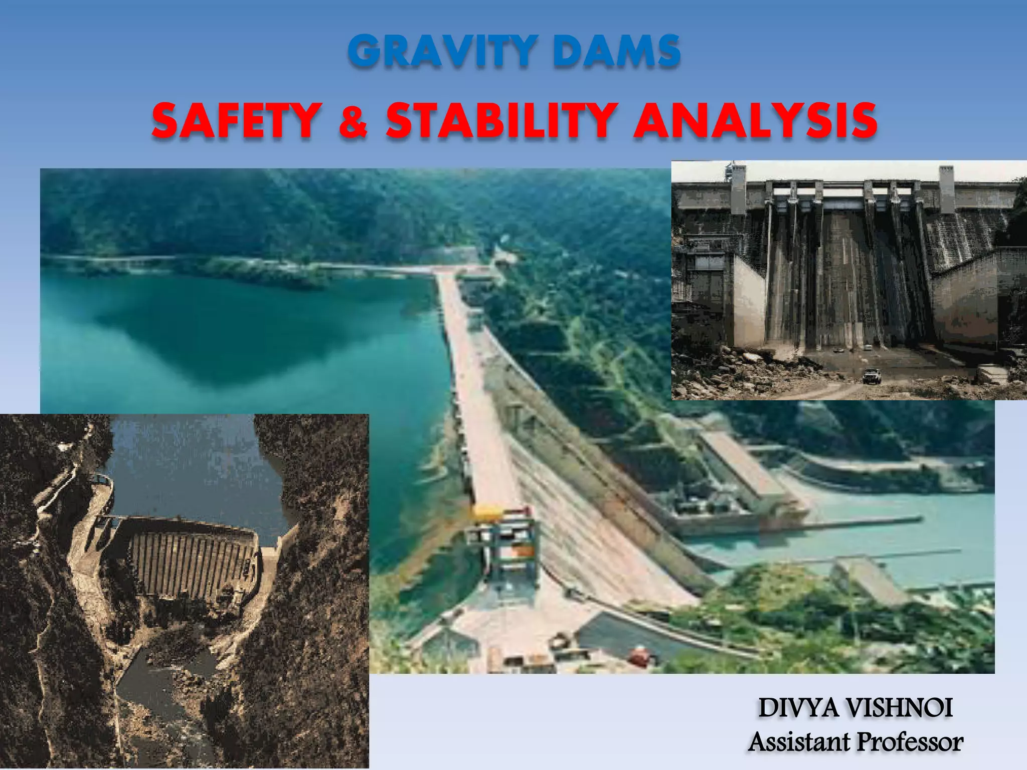

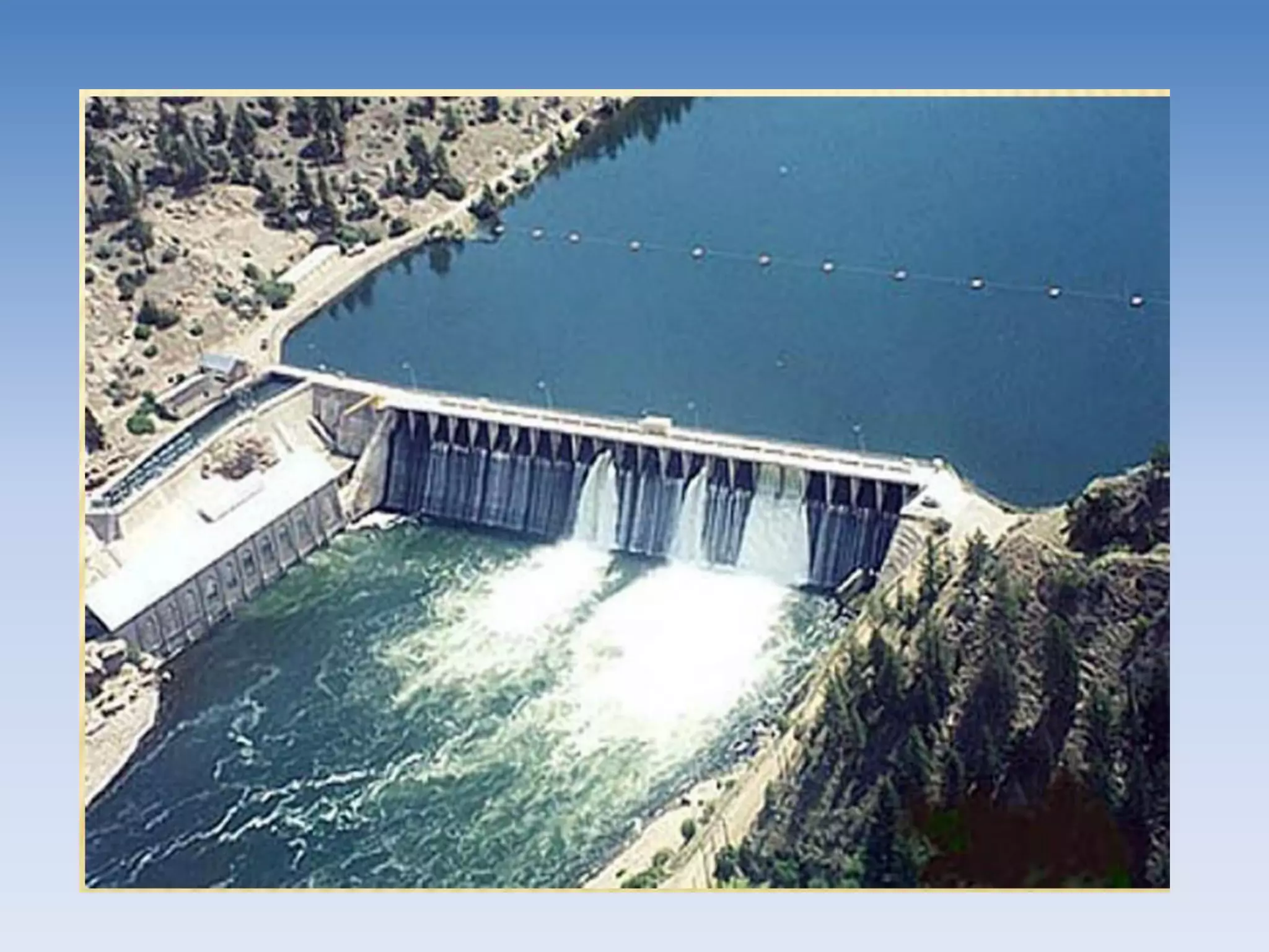
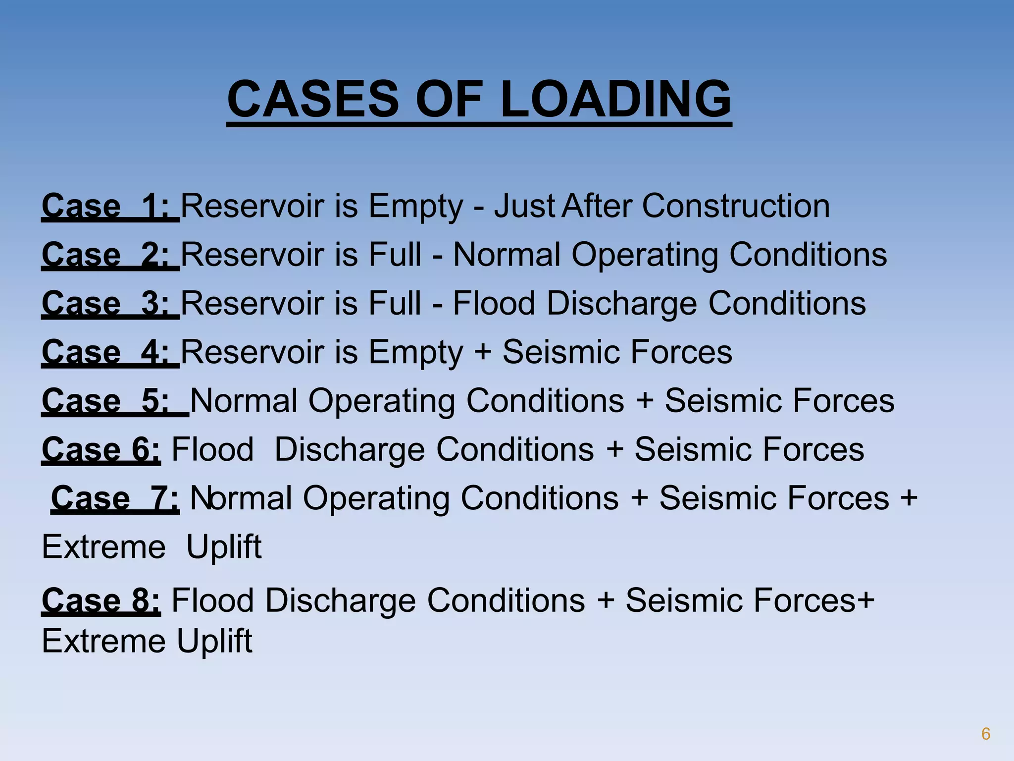
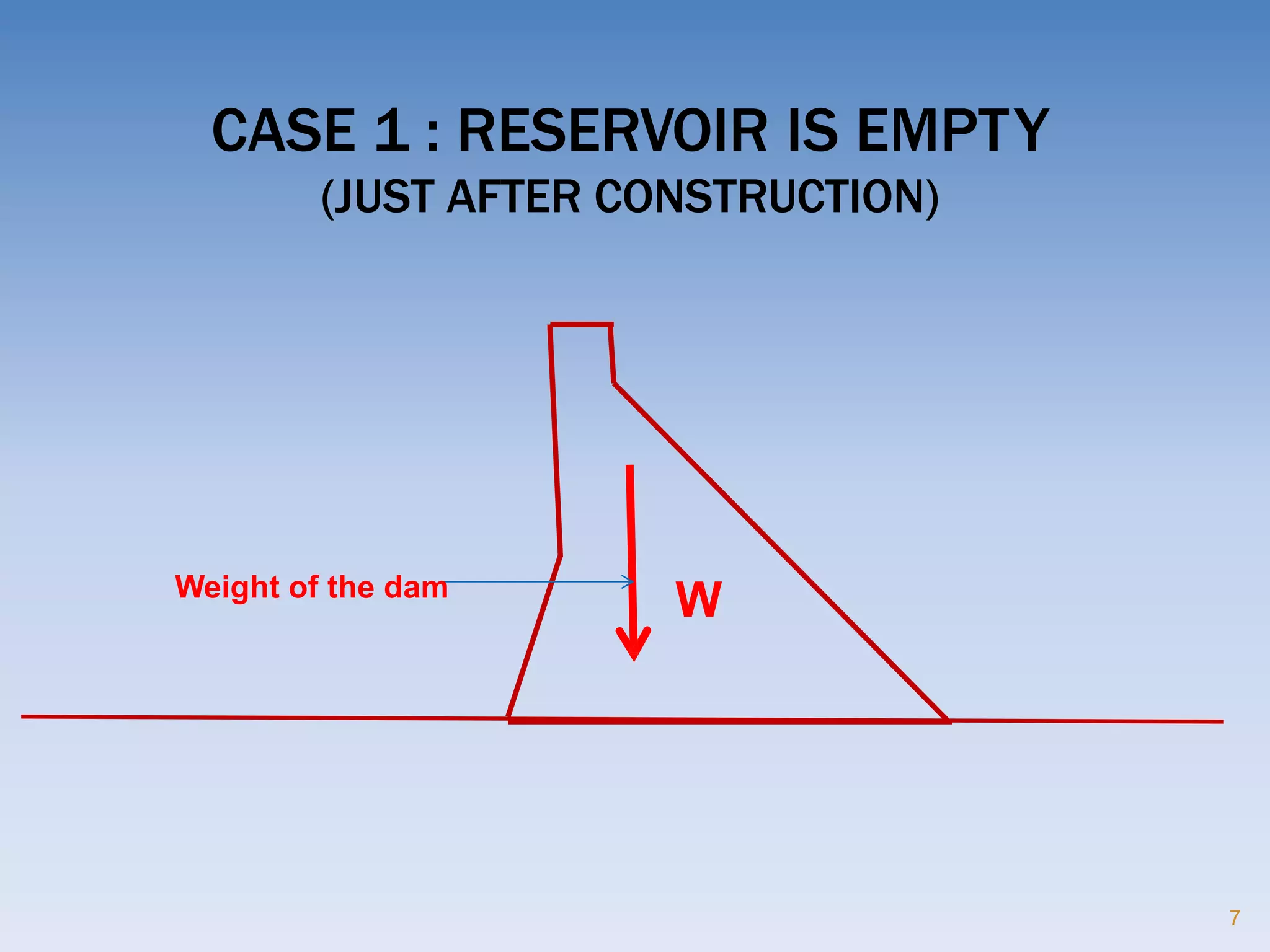
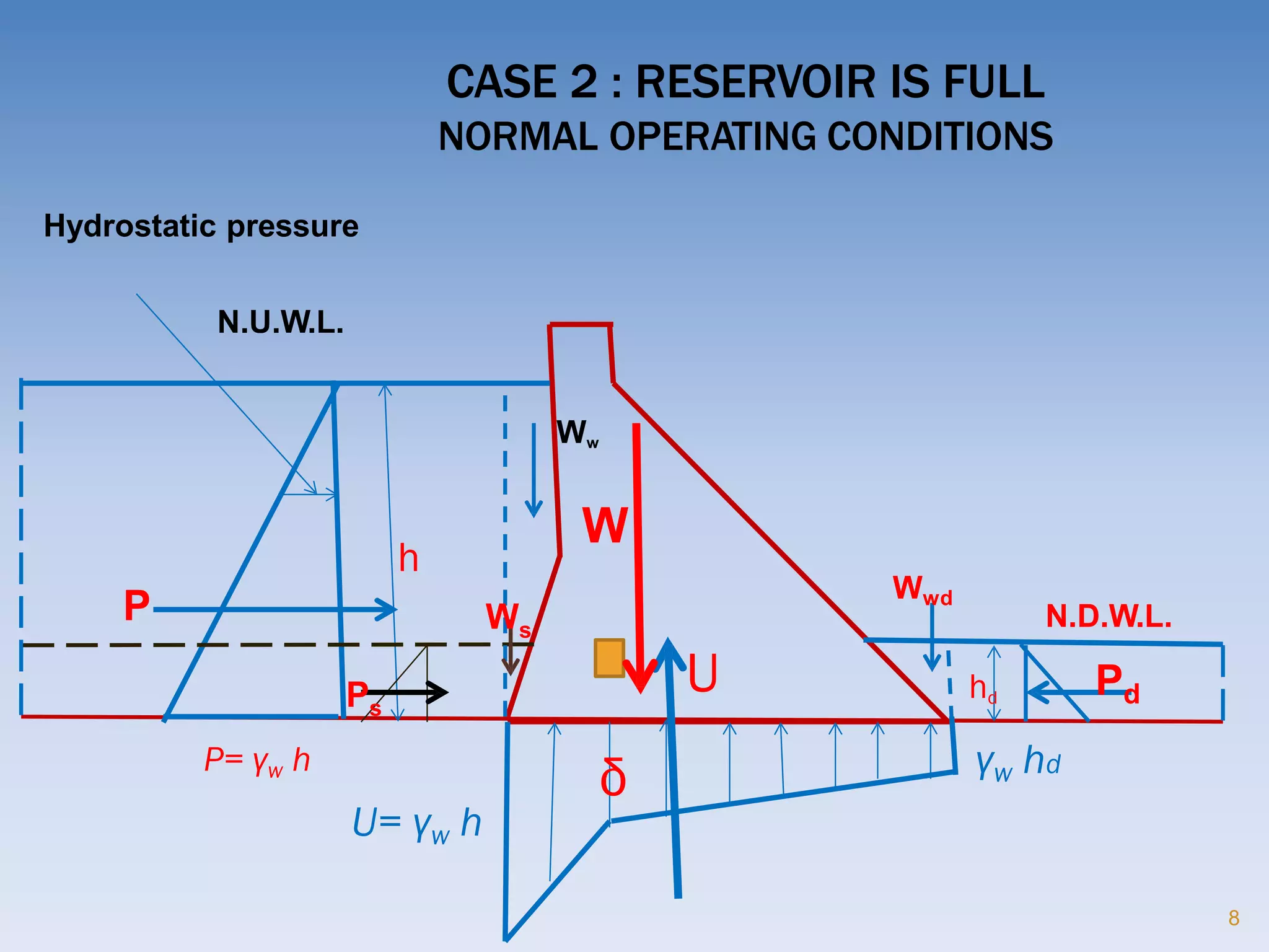
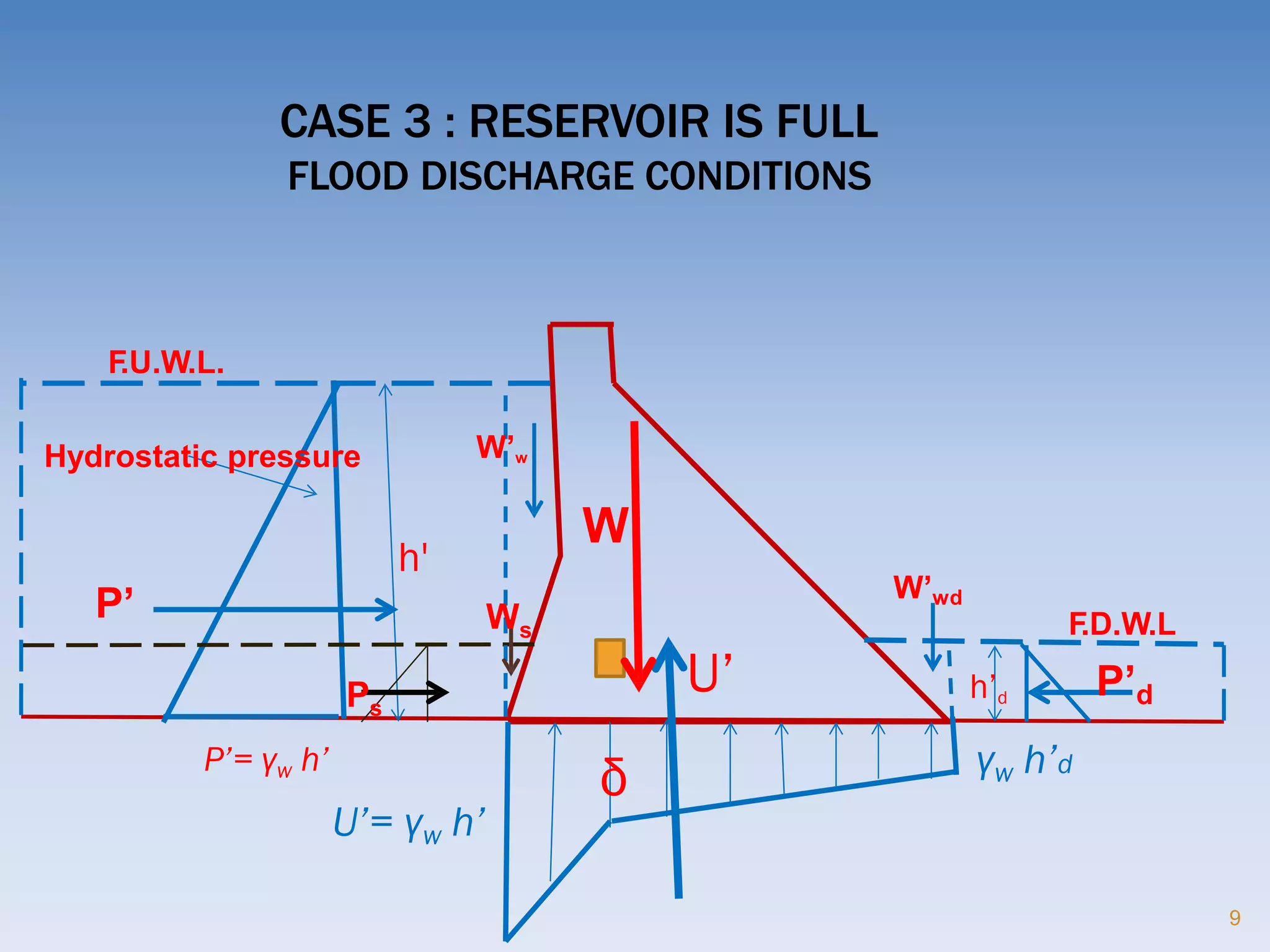
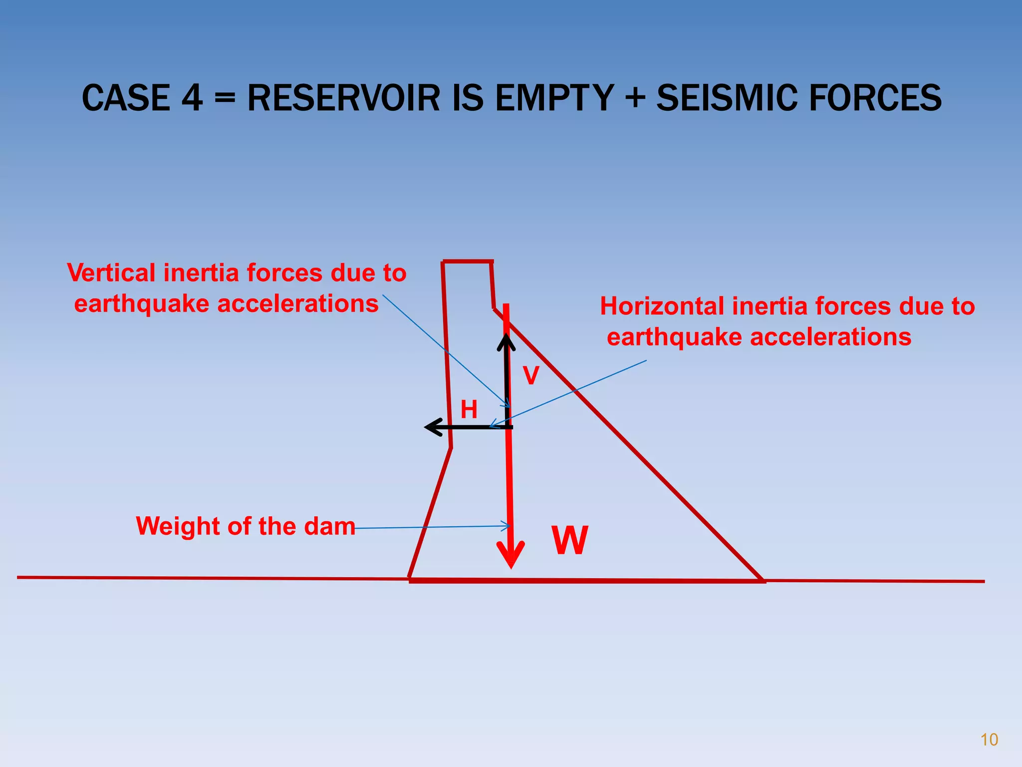
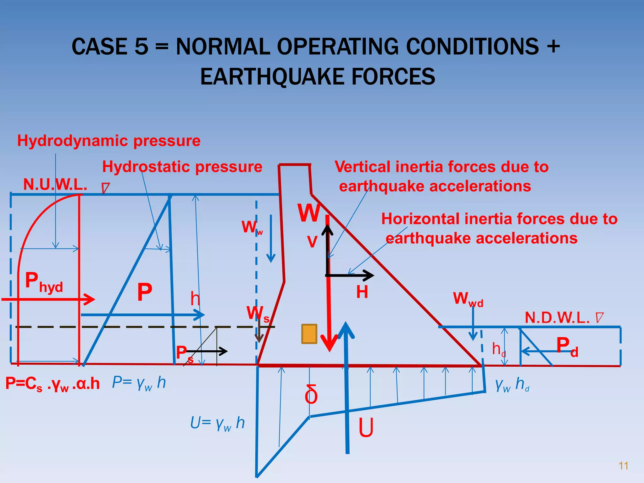
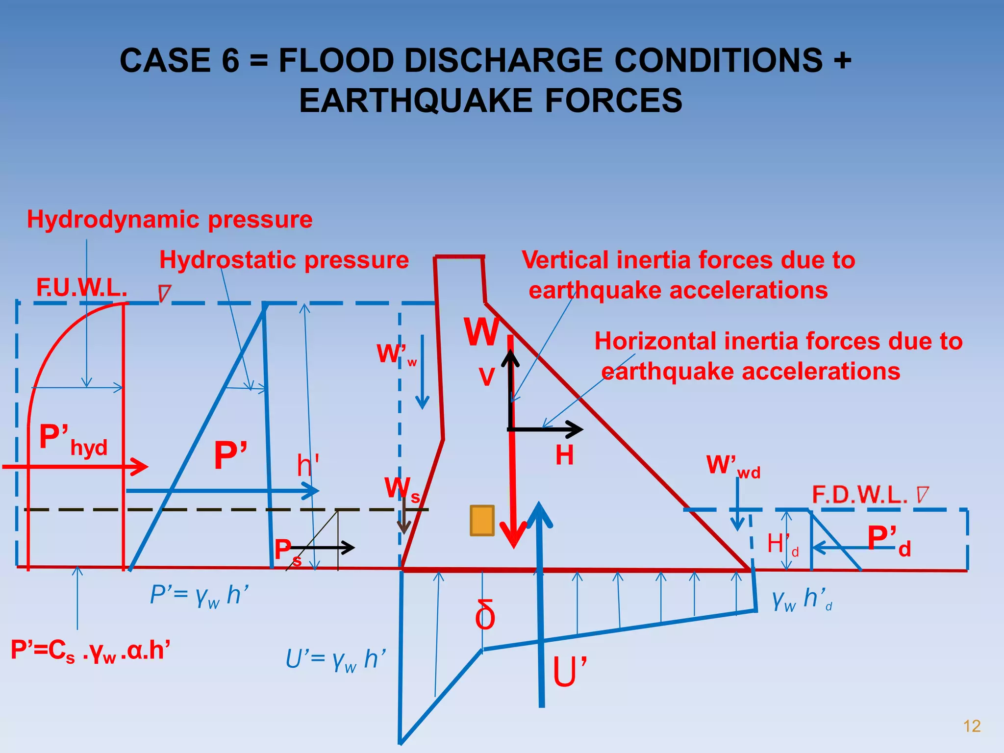
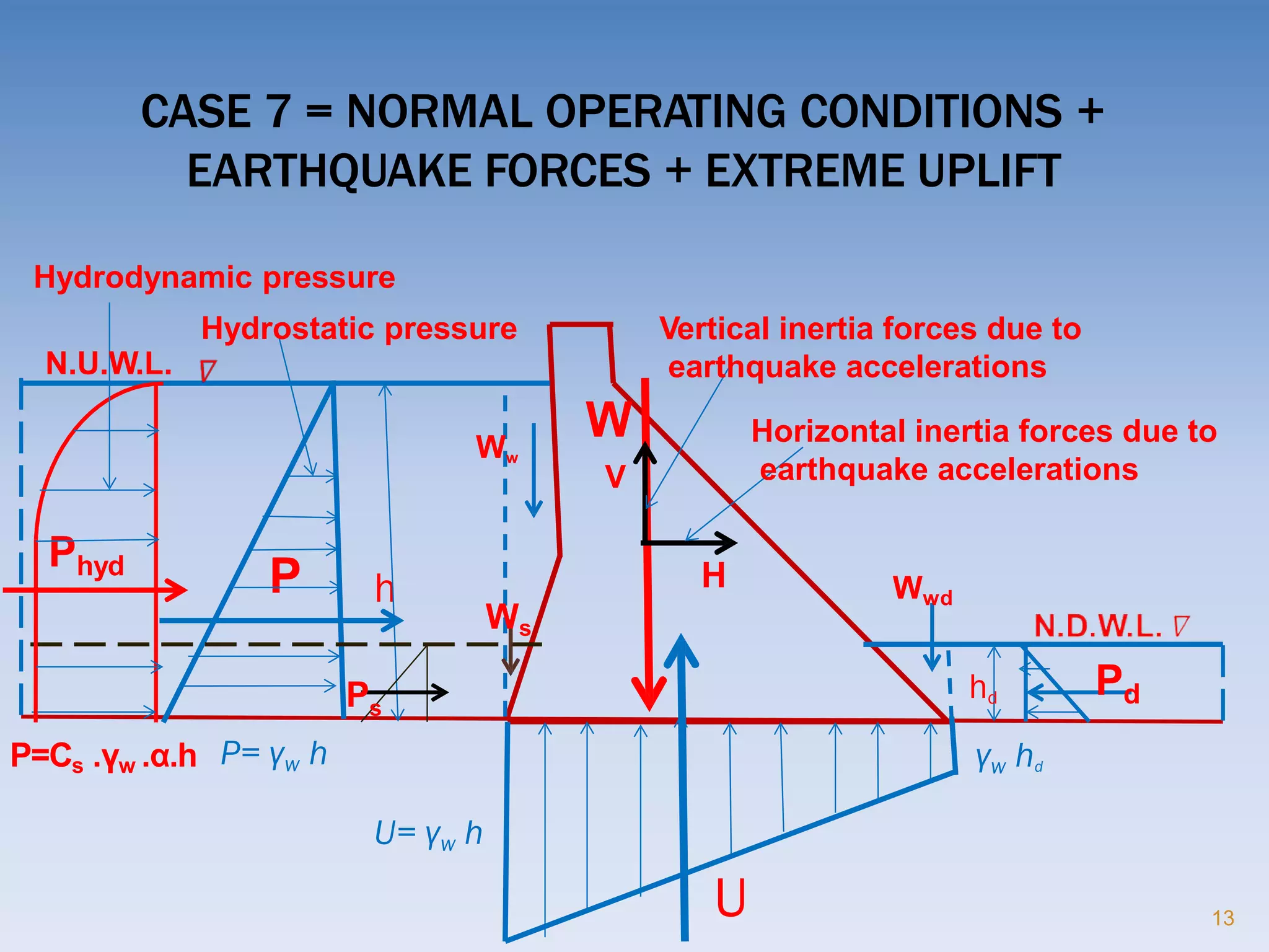
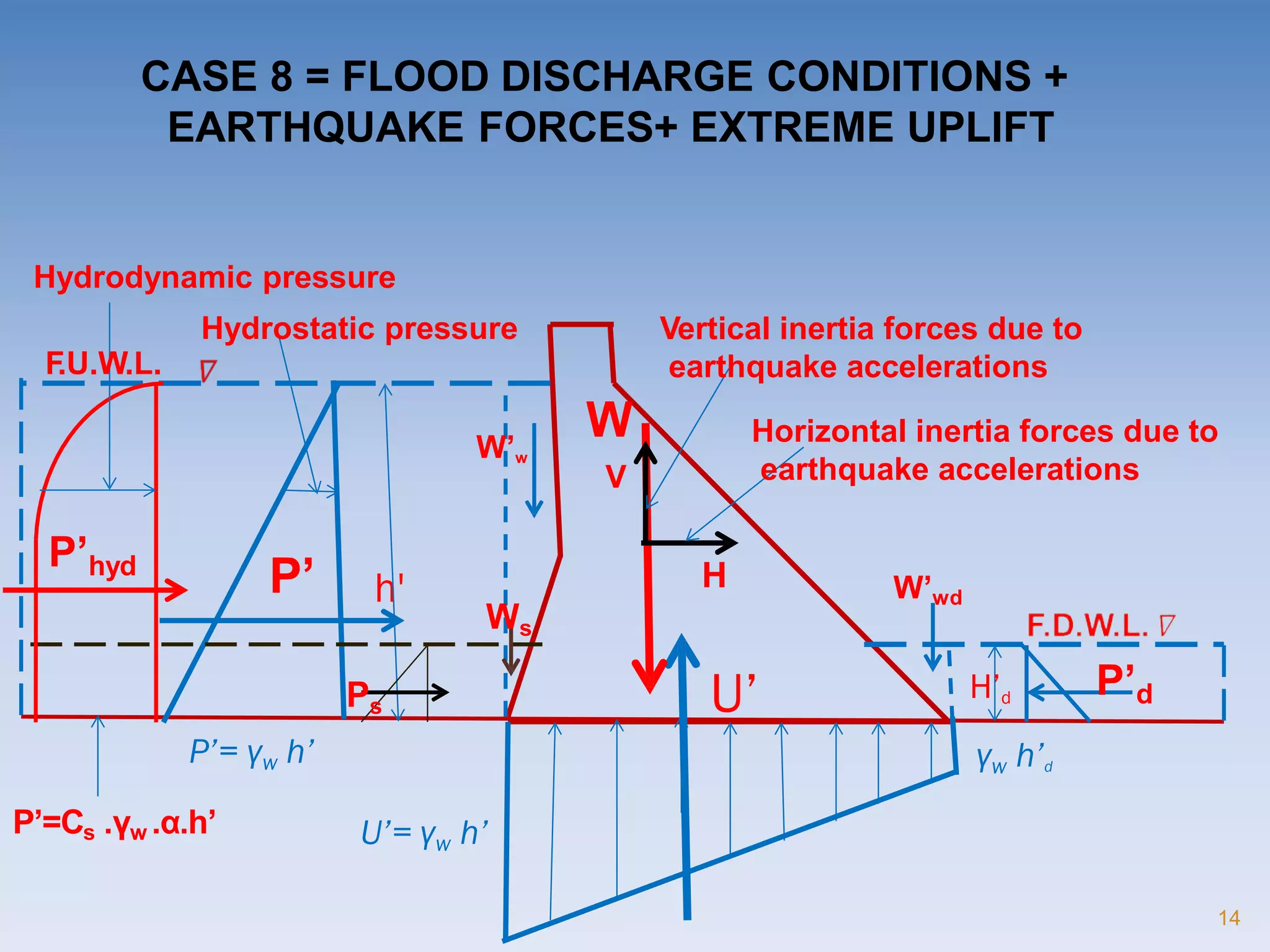


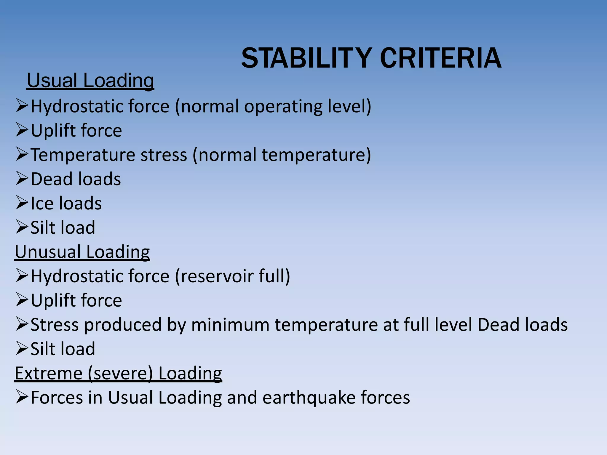
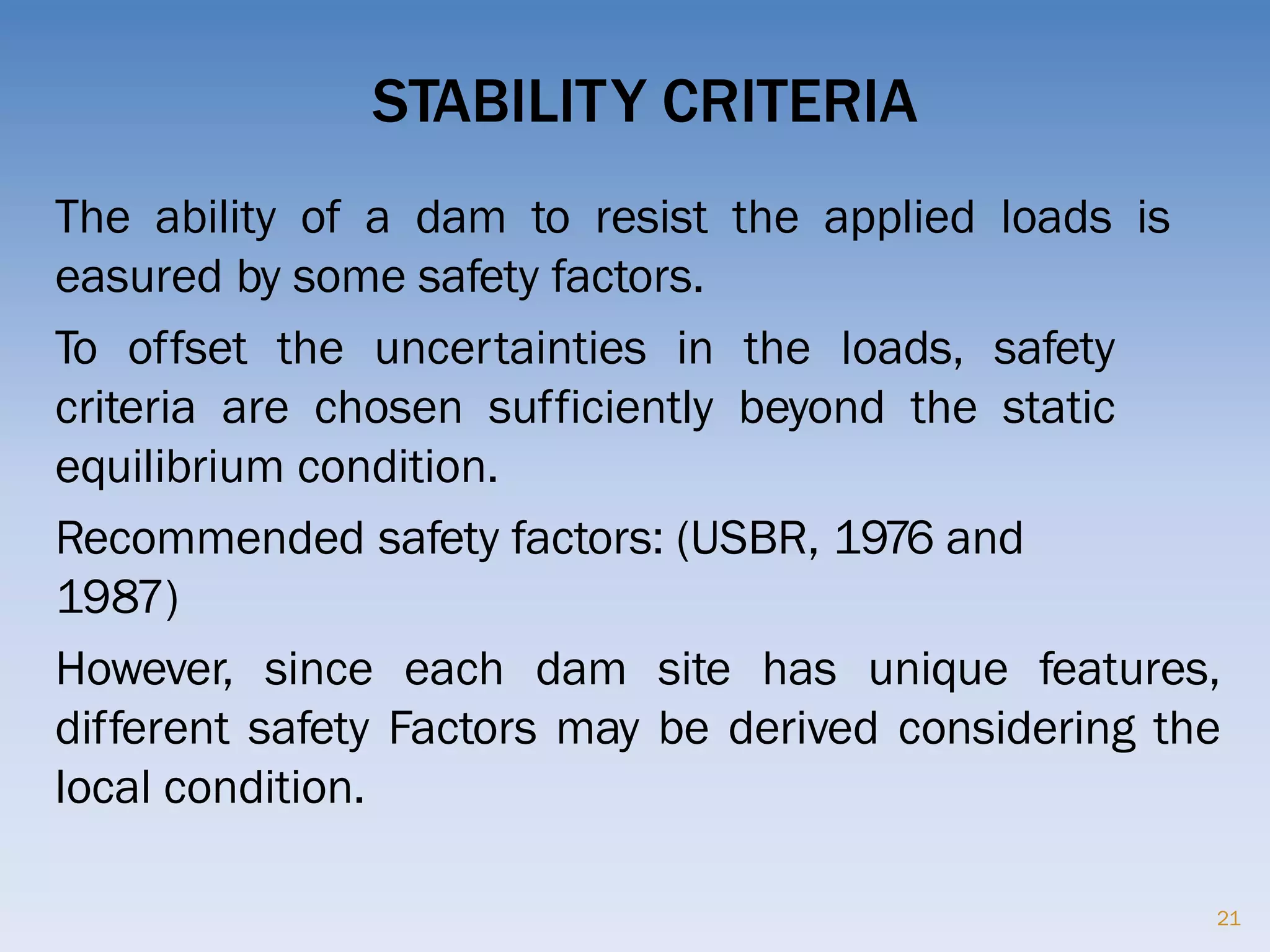
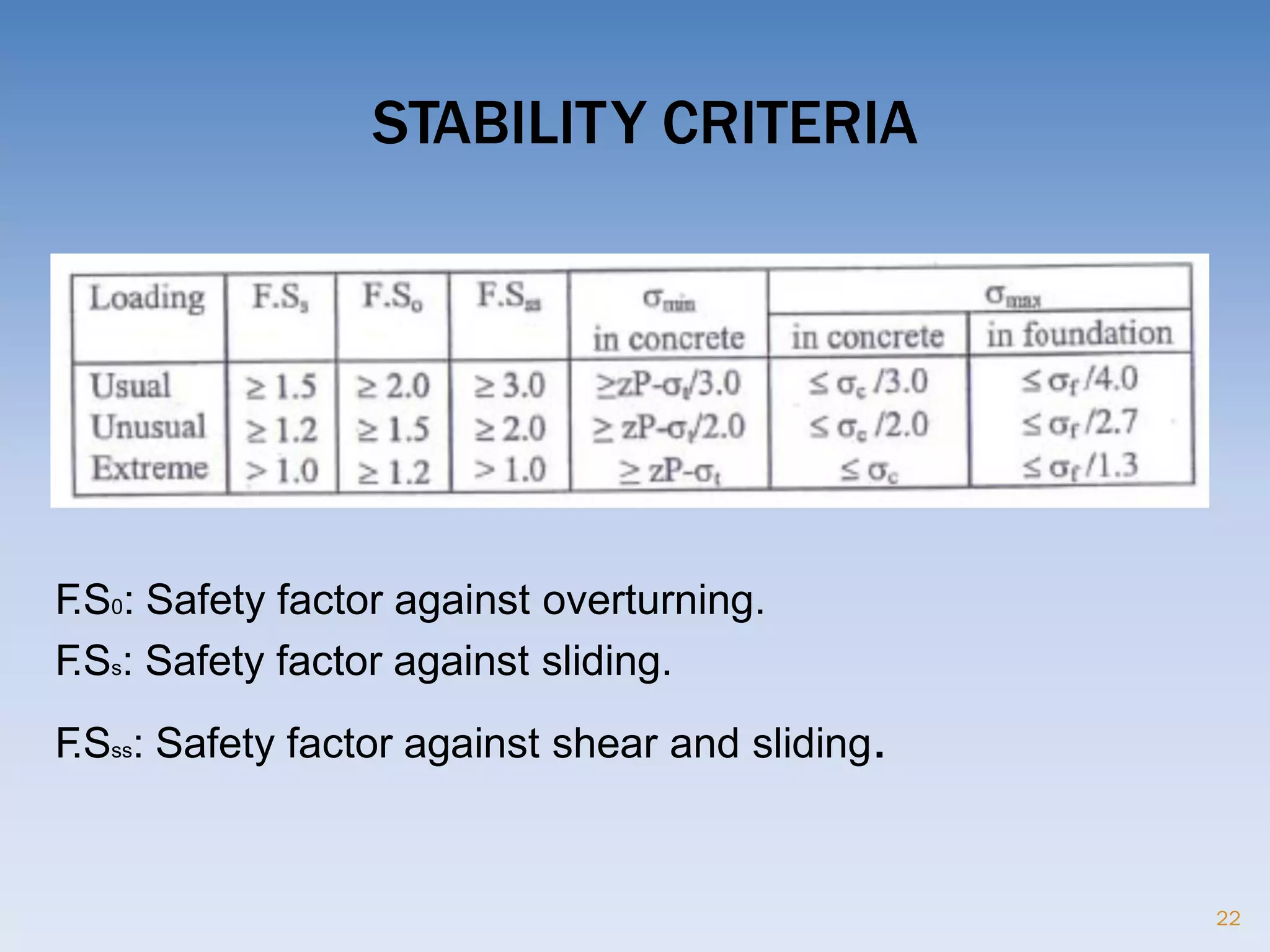
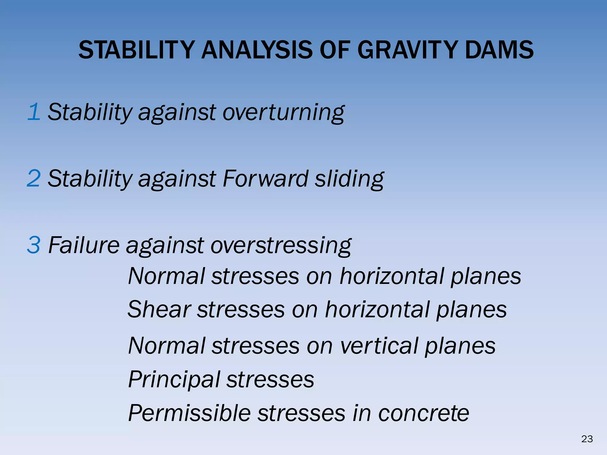
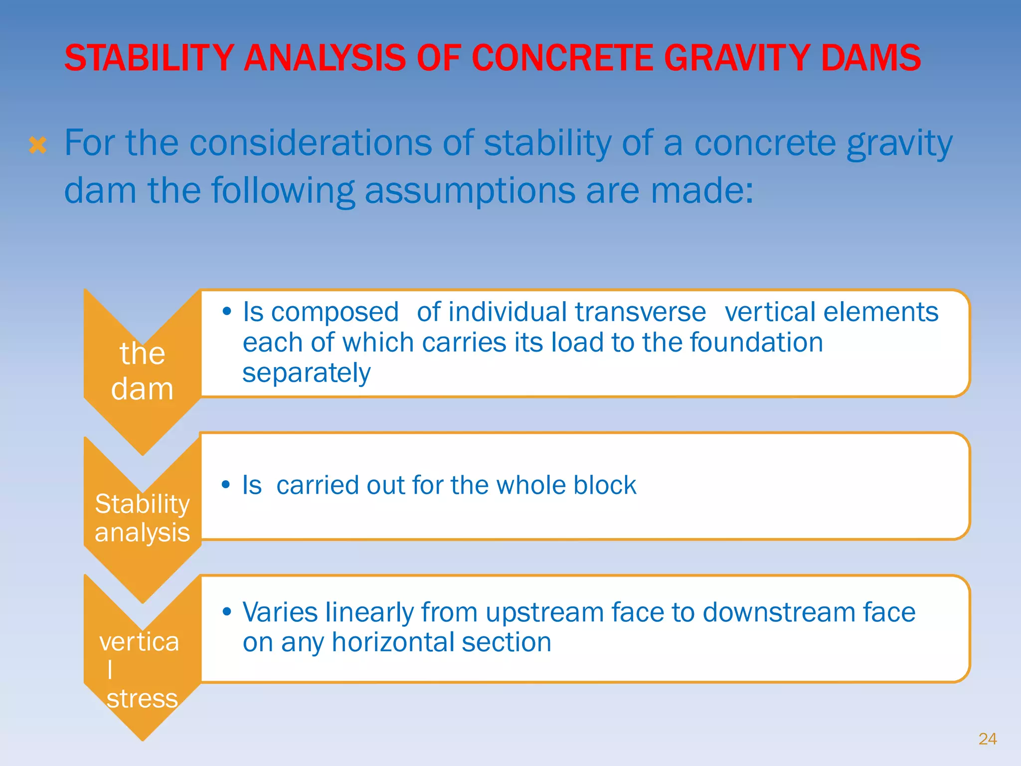
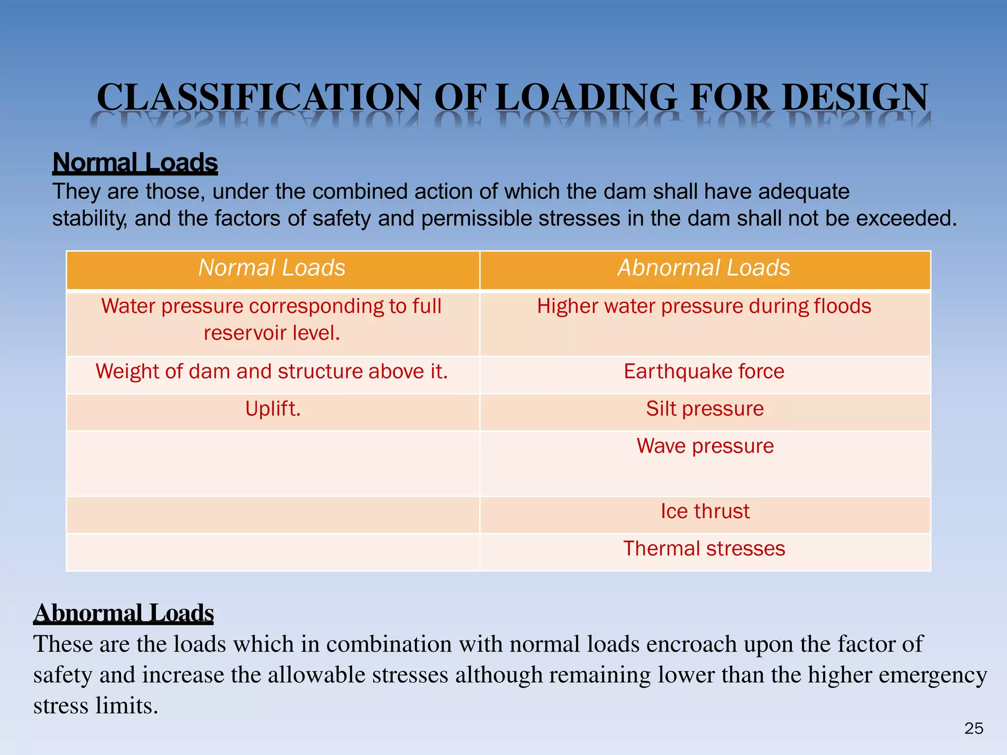
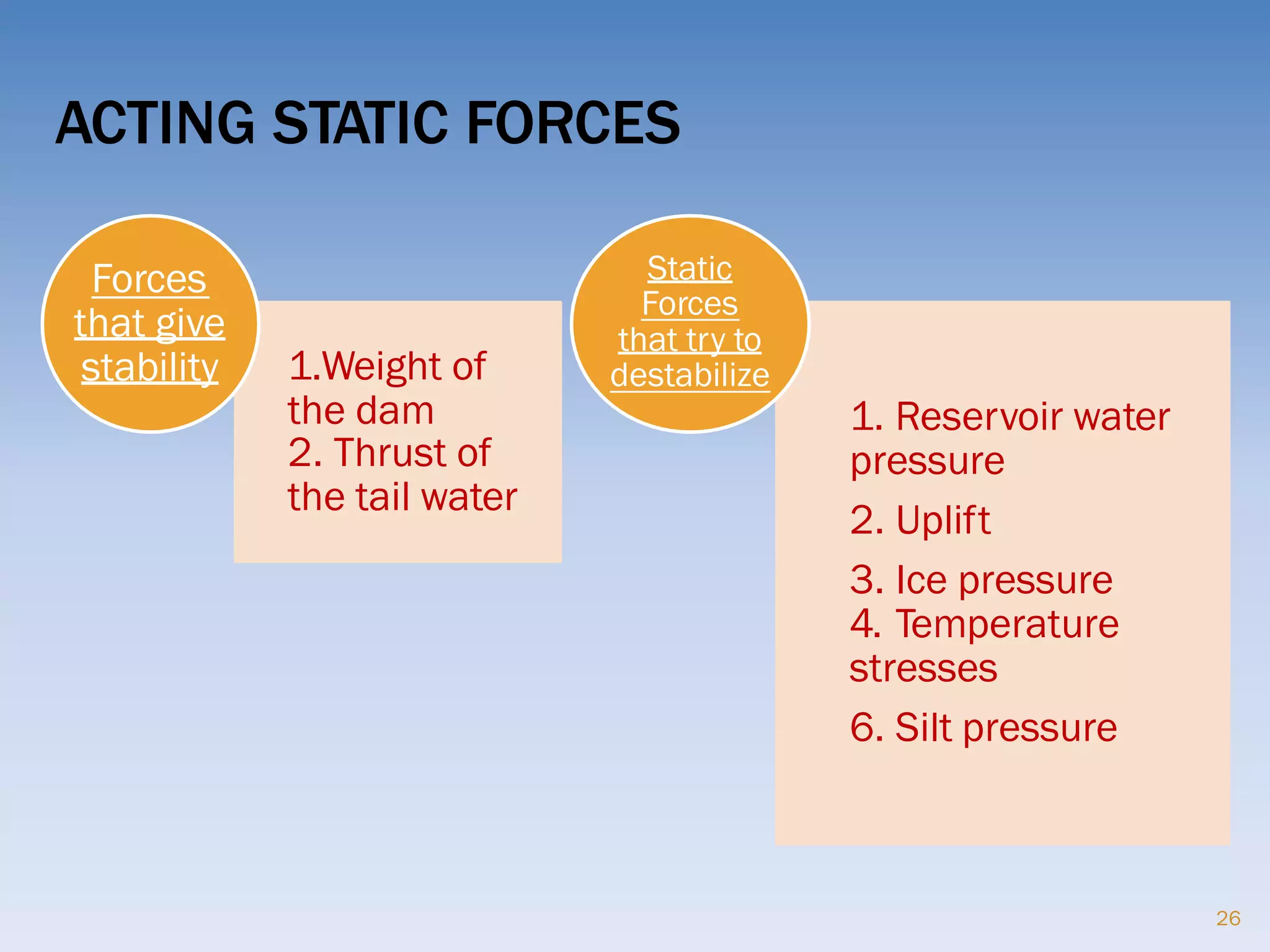
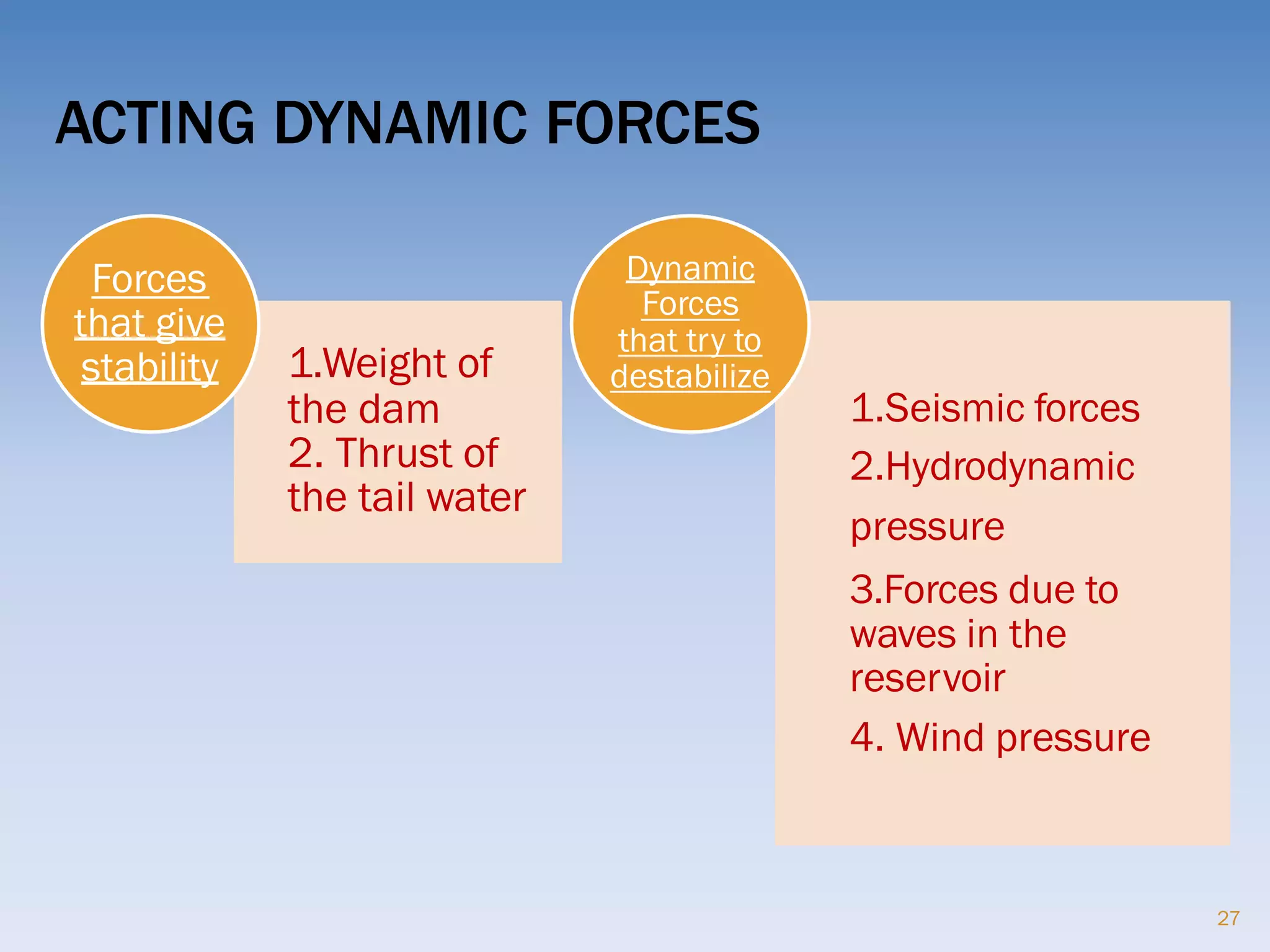
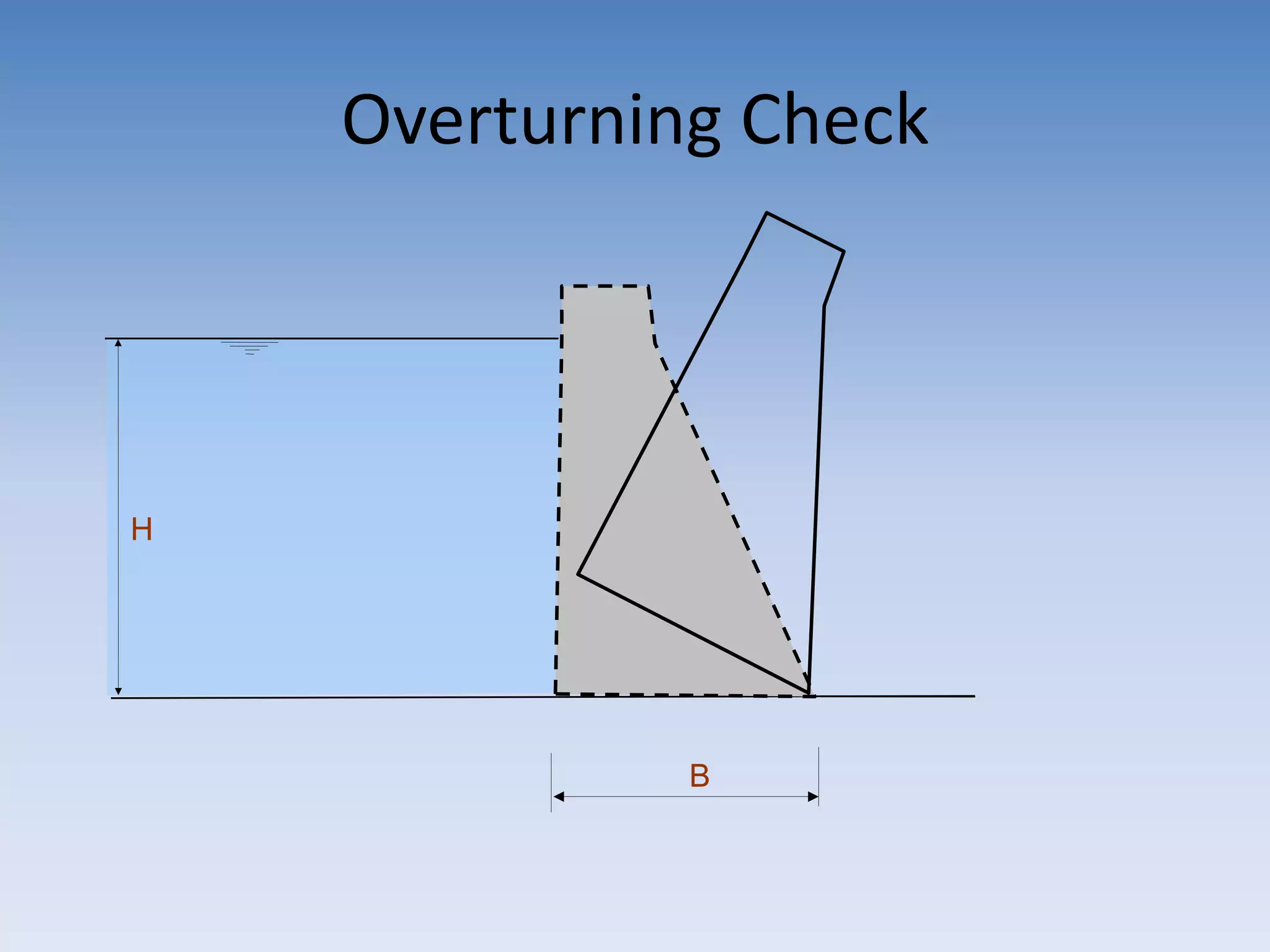
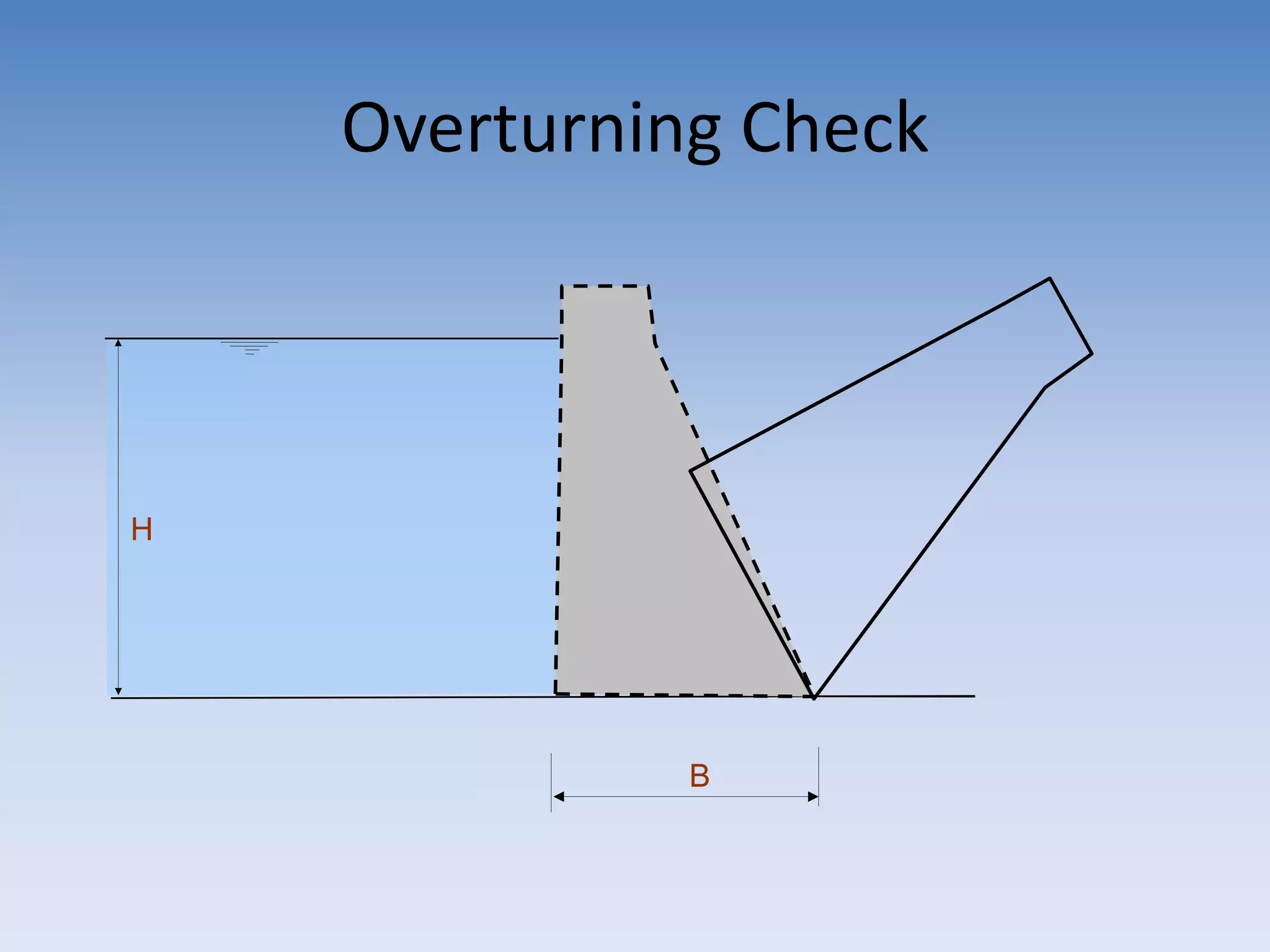
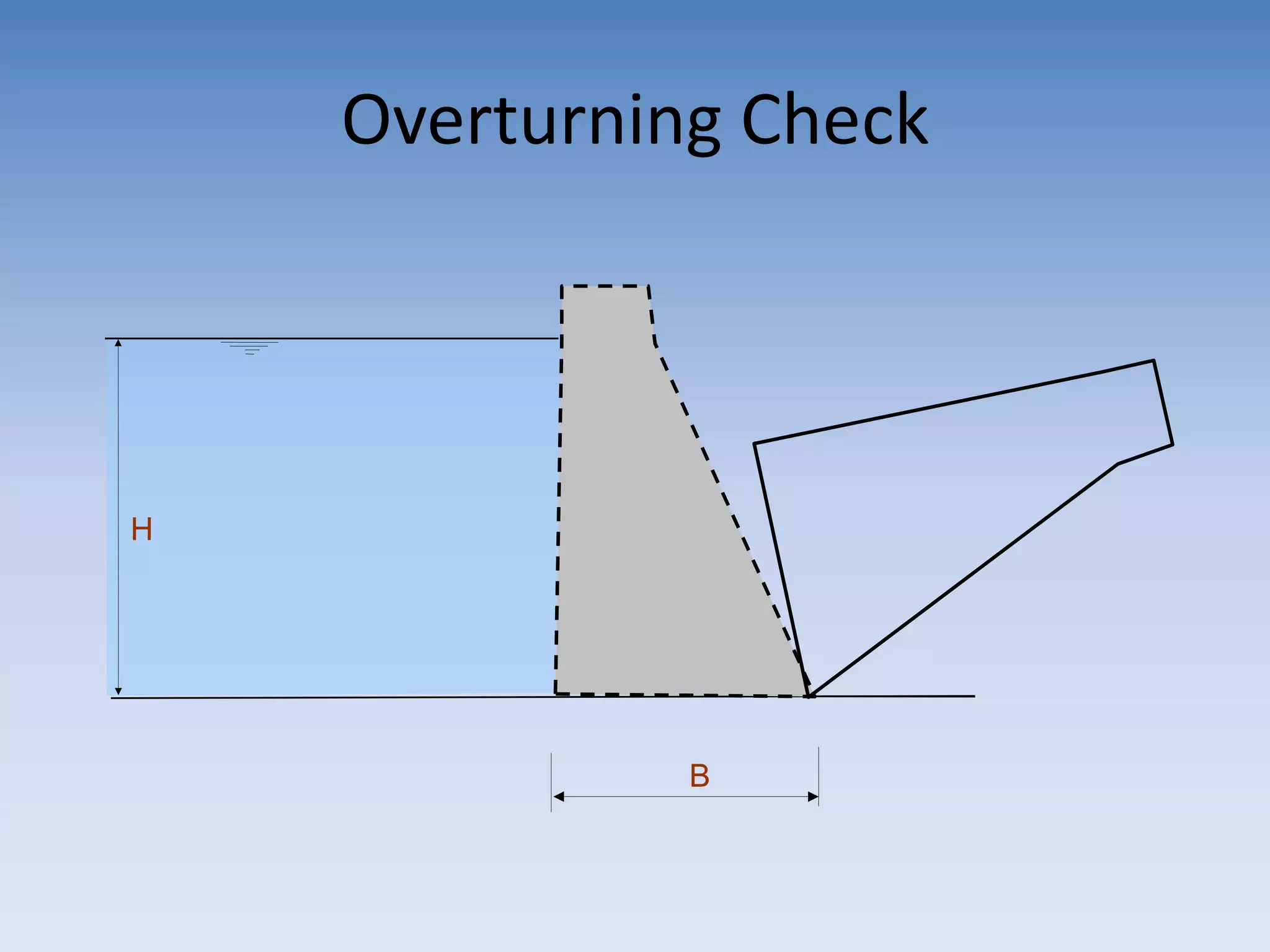
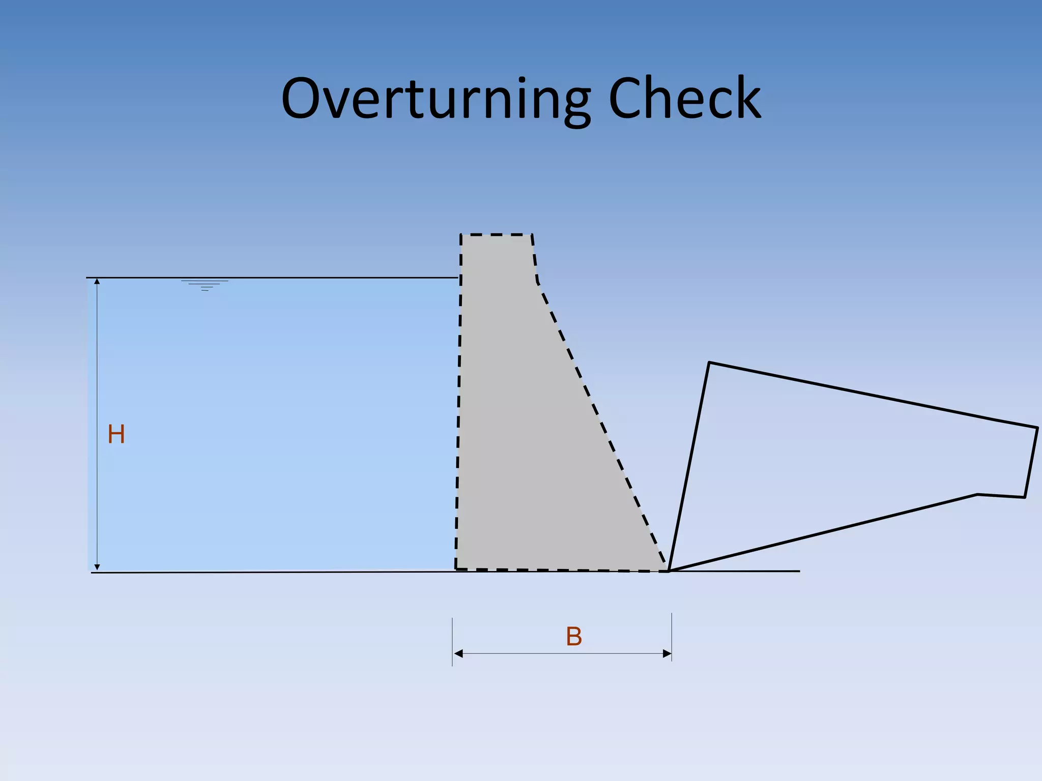
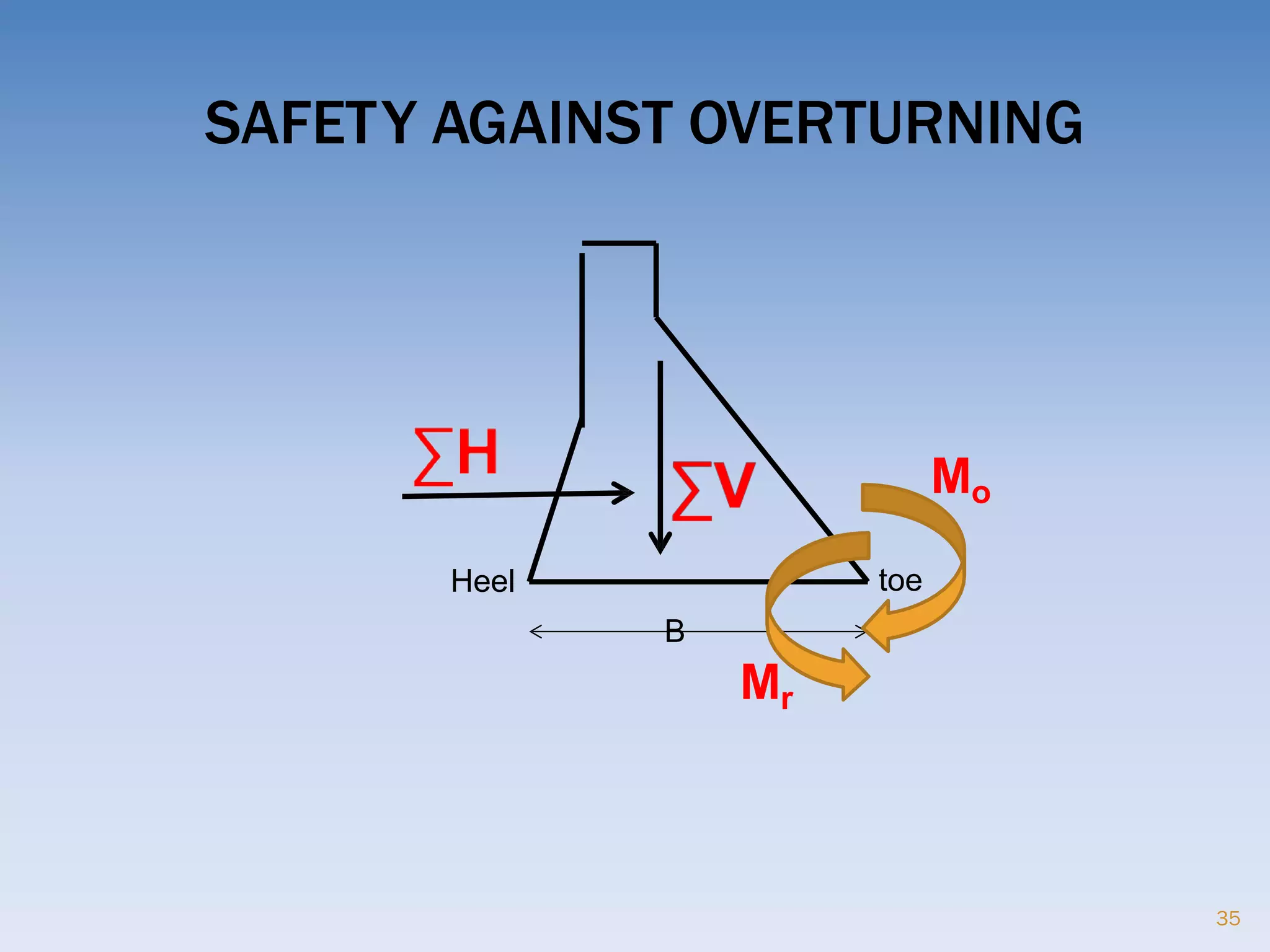
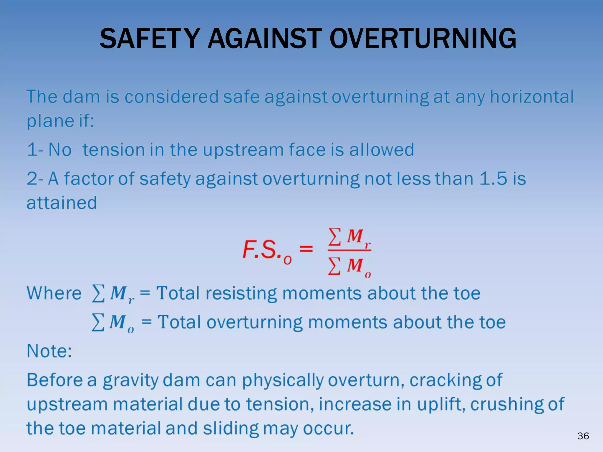

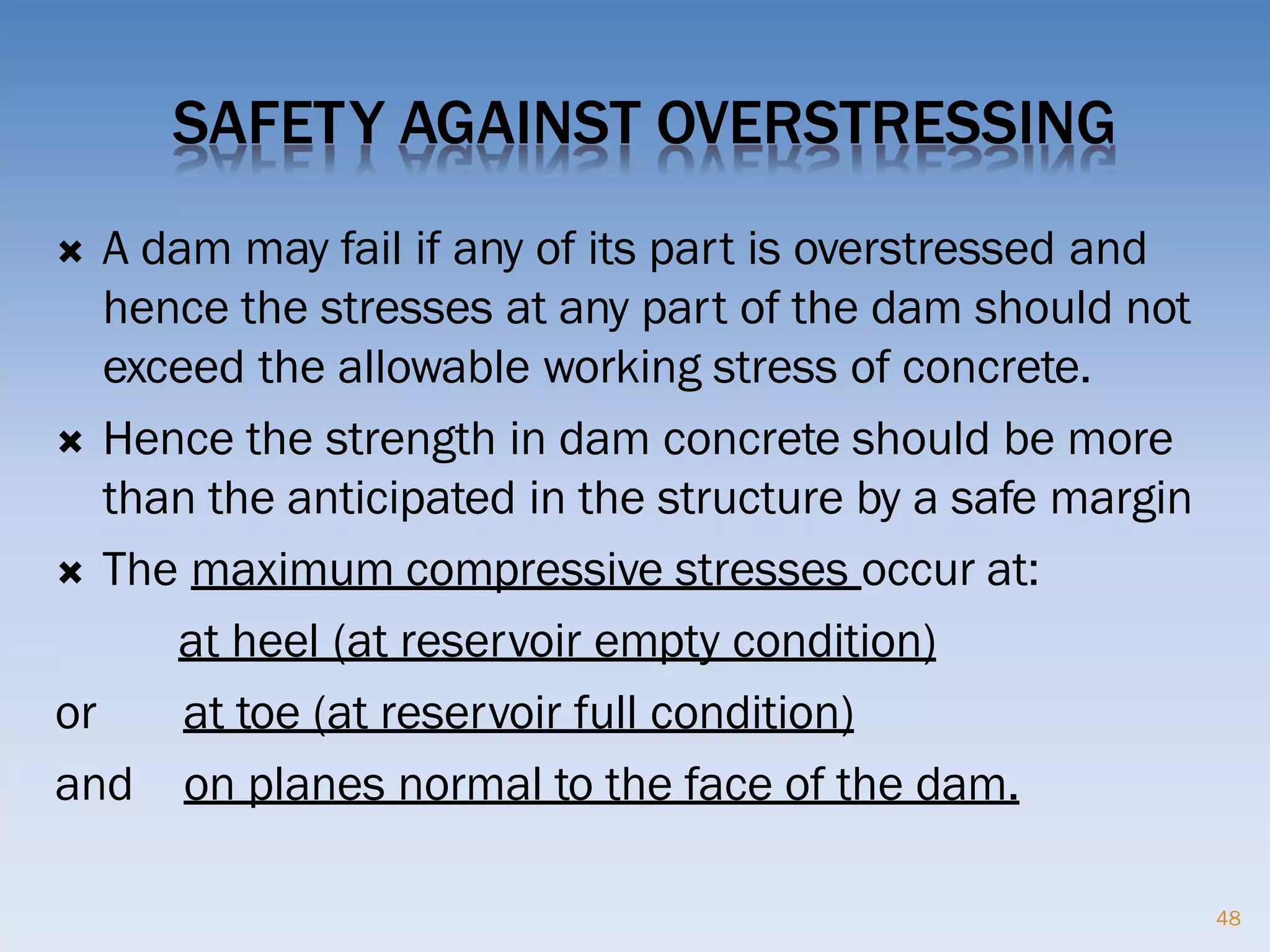
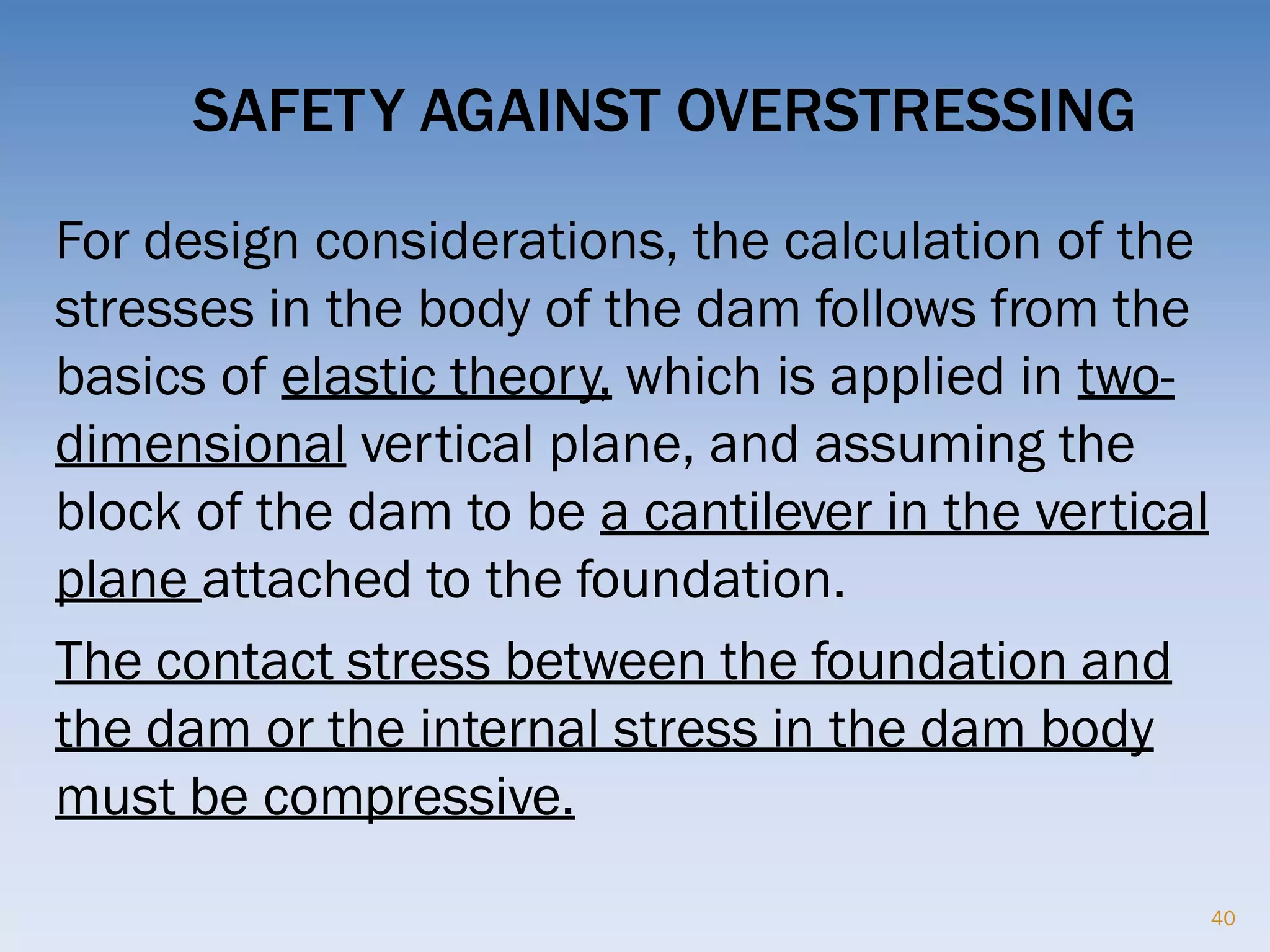
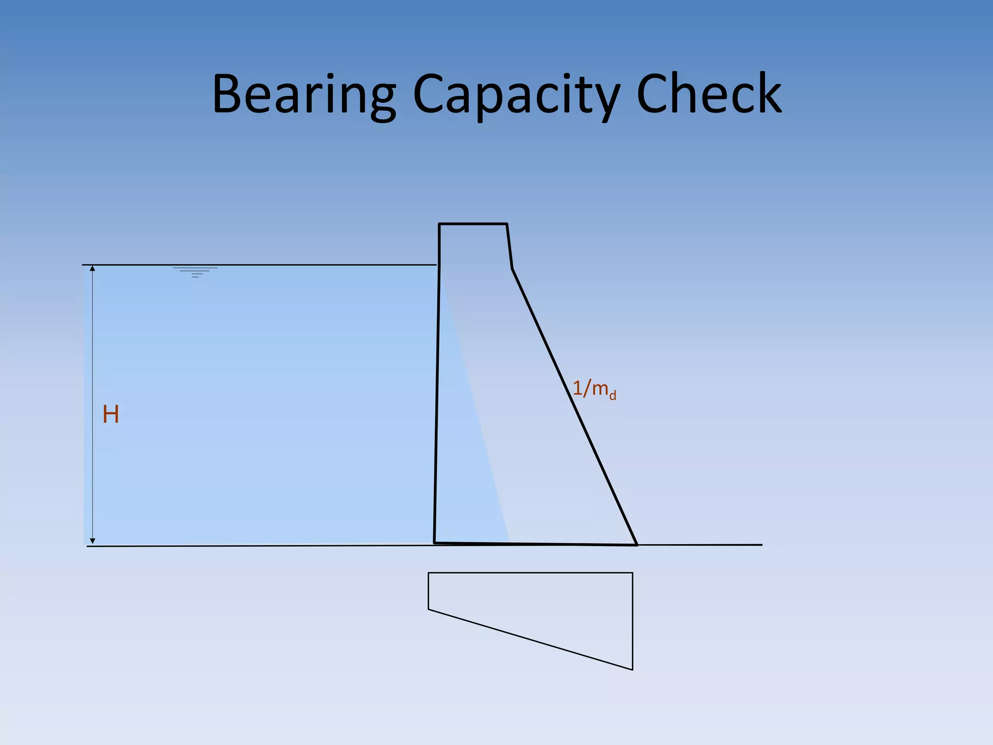
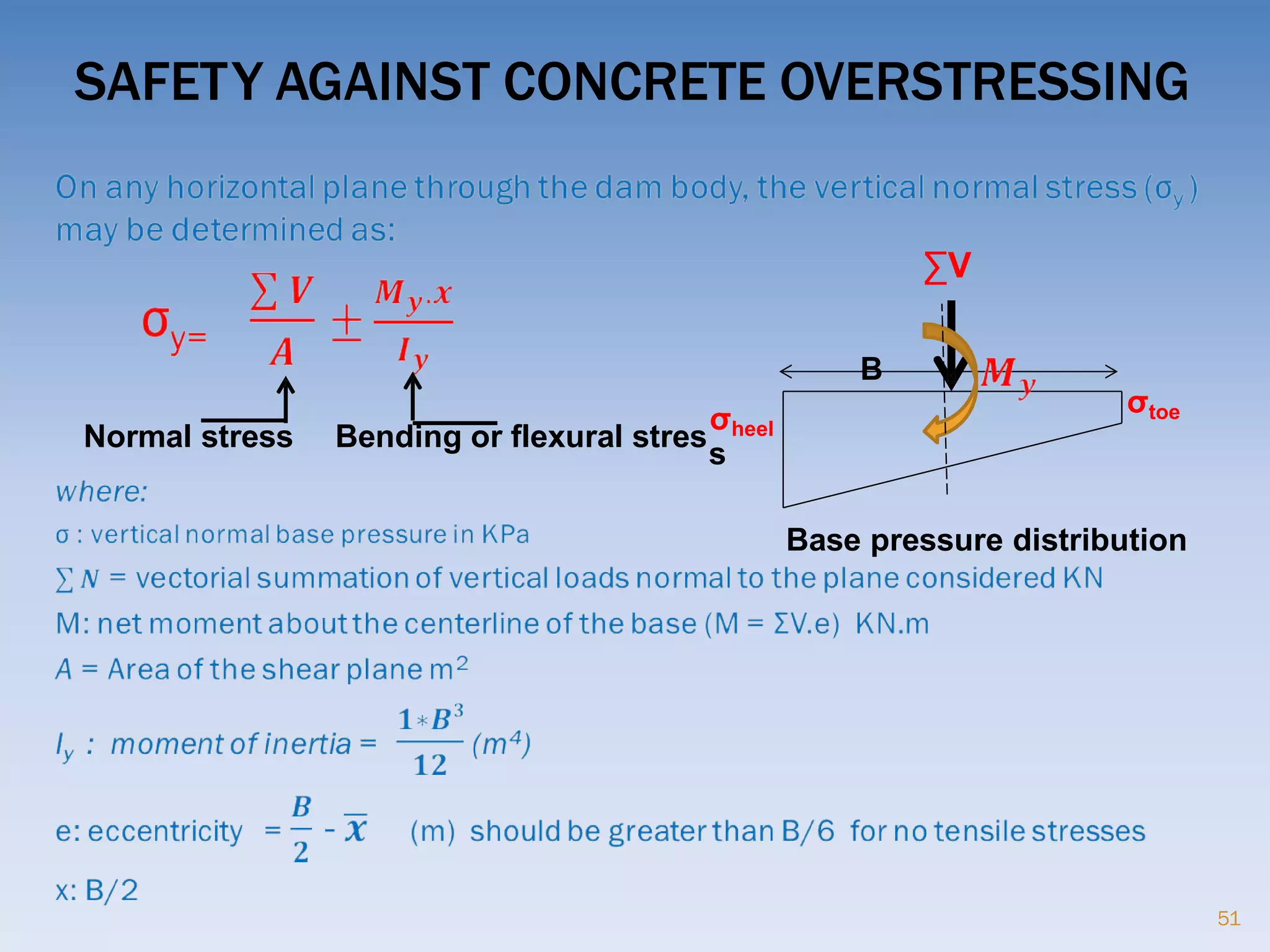
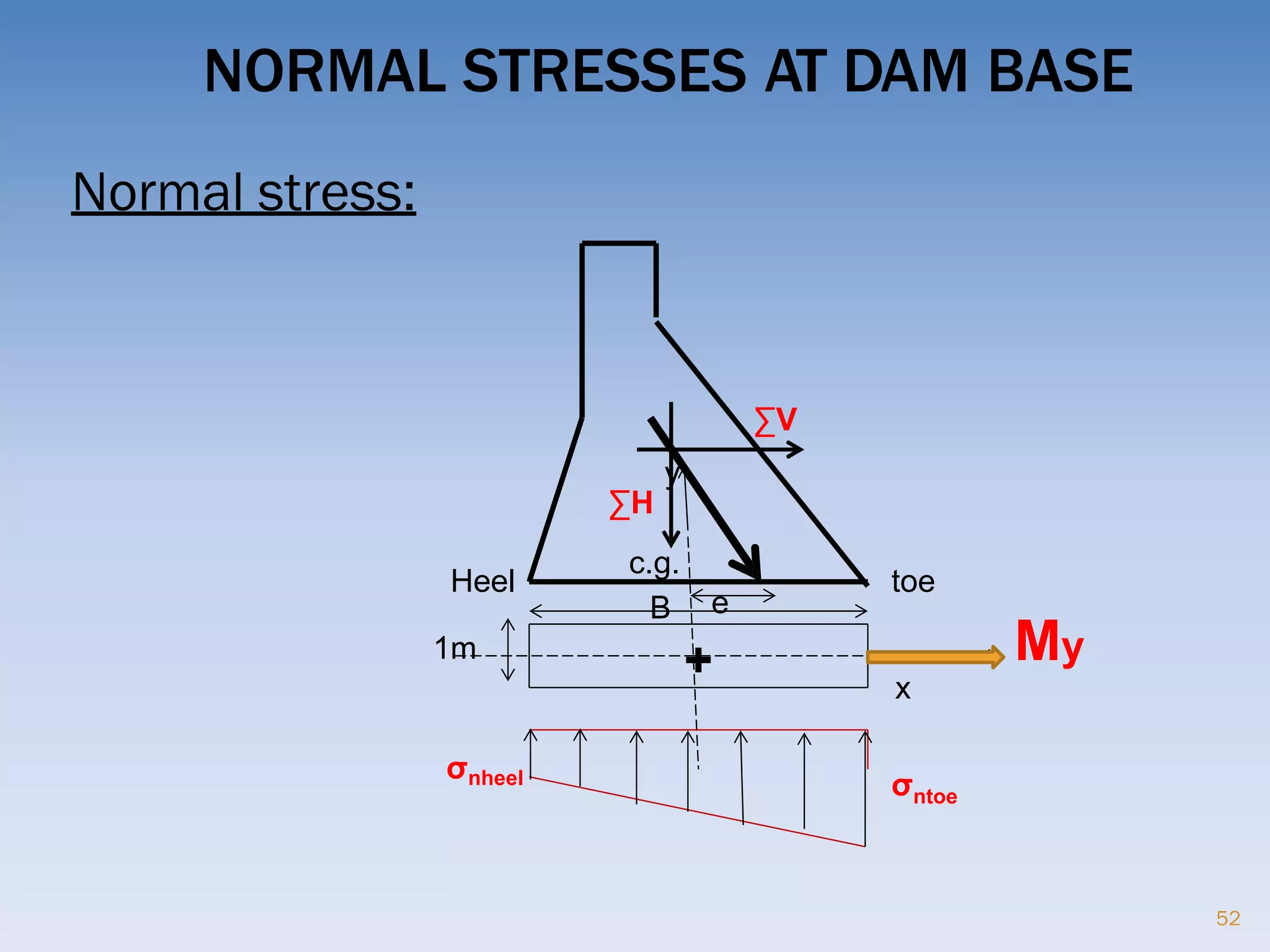
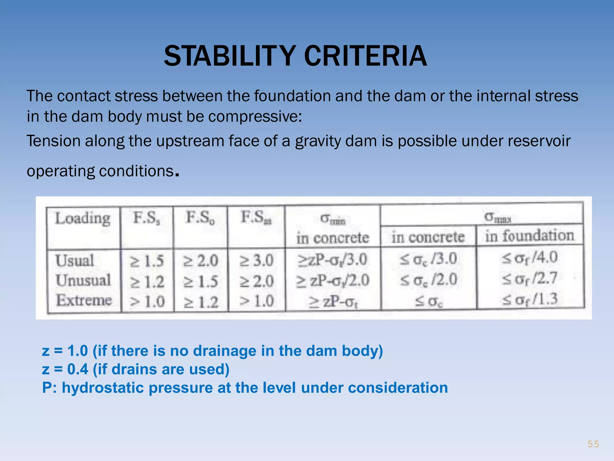


This document provides information on analyzing the stability and safety of concrete gravity dams. It discusses the different loading cases to consider, including empty reservoir, full reservoir under normal and flood conditions, and with seismic forces. It describes analyzing the dam's stability against overturning, sliding, shear stresses, and foundation and concrete overstresses. The document outlines the assumptions made in stability analysis and the recommended safety factors. It also discusses determining normal and principal stresses in the dam, and ensuring compressive stresses are maintained.


