This document discusses forces acting on concrete gravity dams, including uplift pressure. Uplift pressure is an important force to consider in gravity dam design and safety, as it can compromise structural integrity, especially in cracked dams. The document outlines the traditional approach to modeling uplift pressure as varying linearly from full reservoir pressure at the base upstream to zero pressure downstream. It notes that a more conservative modern approach is to apply uplift pressure across the full base area. Proper consideration of uplift pressure is crucial for gravity dam safety evaluations and design.


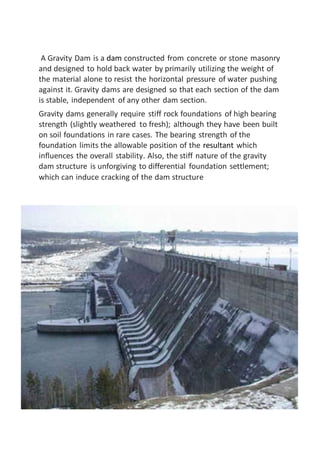

![of the foundation. In addition, a grout curtain positioned upstream of a
drain curtain within the dam’s base can also facilitate the reduction of
uplift pressures by eliminating or decreasing the number of seepage
paths.
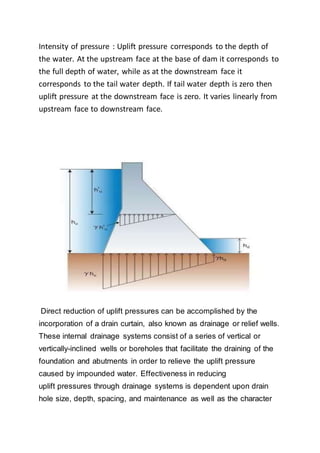
To address the potential for highly variable nature of foundation rock
and concrete properties as well as construction quality within a given
structure “the current design practice [for estimating uplift pressures in
concrete gravity dams] relies heavily on simple empirical rules… It is
assumed that uplift pressure at the base of a dam without drains
varies linearly from full reservoir pressure at the heel to tailwater at the
toe. For dams with foundation drains, the pressure is assumed to
follow a bi-linear tailwater plus some fraction of the difference between
headwater and tailwater at the line of drains, to tailwater at the toe.
Prior to the 1920s, many gravity dams in the United States were
designed without any allowance for uplift. The general view was that
uplift could not develop at the base of a gravity dam to any significant
degree since the dam by its own weight placed the structure in positive
contact with its foundation. After some highly publicized dam failures in](https://image.slidesharecdn.com/adam-170828145757/85/Gravity-dams-13-320.jpg)