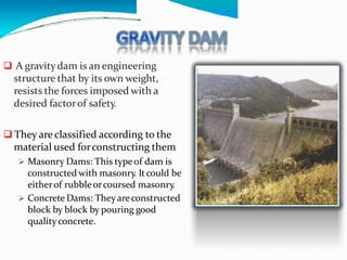
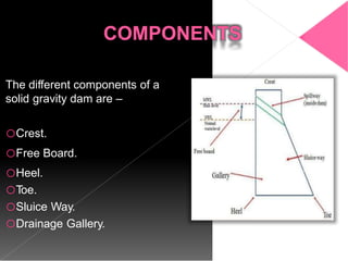
2. A dam is an impervious high barrier which is constructed
across a valley to form a deep storage reservoir.
Its suitable in the hilly regions where a deep gorge
section is available for the storage reservoir.
It is meant for serving multipurpose functions
Irrigation.
Hydroelectric Power Generation.
Flood Control.
Water Supply.
Fishery.
Recreation.
such as –
3. Based on Materials of Construction
Rigid.
Non-Rigid.
–
Based on Structural Behaviour
Gravity Dam.
Arch Dam.
Buttress Dam.
Embankment Dam.
Based on Functions –
Storage Dam.
Detention Dam.
Diversion Dam.
Coffer dam.
–
Based on Hydraulic Behaviour –
Over Flow Dam.
Non Over Flow Dam.
4. –
A gravitydam is an engineering
structure that by its own weight,
resists the forces imposed with a
desired factorof safety.
They are classified according to the
material used forconstructing them
Masonry Dams: This type of dam is
constructed with masonry. Itcould be
eitherof rubbleorcoursed masonry.
Concrete Dams: Theyareconstructed
block by block by pouring good
qualityconcrete.
5. The different components of a
solid gravity dam are –
oCrest.
oFree Board.
oHeel.
oToe.
oSluice Way.
oDrainage Gallery.
6. dam are –
Self Weight.
Hydraulic Pressure.
Uplift Force.
Wave Pressure.
Wind Pressure.
Seismic Force.
7. •The self weight of the gravity dam is the n stabilising force
which counter balances all the external forces acting on it.
•For construction of gravity dams the specific weight of
than 2400 kg/m3
concrete & stone masonry shouldn’t be le
& 2300 kg/m3 respectively.
•The self weight of the gravity
gravity of the.
dam acts the centre of
•Its calculated by the following formula –
Where γm is the specific weight of the s material.
8. Water Pressure is the most major
external force acting on a gravity dam.
On upstream face pressure exerted
by water is stored upto the full
reservoir level. The upstream face may
either be vertical or inclined.
On downstream face the pressure is
exerted by tail water. The downstream
face is always inclined.
It is calculated by the following
formula –
Where γw is the unit weight of water & h
is the height of water.
9. The water stored on the upstream side
of the dam has a tendency to seep
through the soil below foundation.
While seeping, the water exerts a uplift
force on the base of the dam depending
upon the head of water.
This uplift pressure reduces the self
weight of the dam.
T
o reduce the uplift pressure, drainage
galleries are provided on the base of the
dams.
It is calculated by the following formula –
1
whB
U
2
Where ‘B’ is the width of the base of the dam.
10. When very high wind flows over the
water surface of the reservoir, waves are
formed which exert pressure on the
upstream part of the dam.
The magnitude of waves depend upon
The velocity of wind.
Depth of Reservoir.
Area of Water Surface.
–
It is calculated by the following formula-
Where ‘hw’ is the wave height.
11. WIND PRESSURE
The top exposed portion on the dam is small &
hence the wind pressure on this portion of dam is
negligible.
But still an allowance should be made for the wind
pressure at the rate of about 150 kg/m2 for the
exposed surface area of the upstream & downstream
faces.
12. Dams are subjected to vibration
during earthquakes.
Vibration affects both the body of
0.1 W1
the dam as well as the water
reservoir behind the dam.
in the
0.1 W2
W1
The most danger effect occurs
when the vibration is perpendicular
to the face of the dam.
W2
Body Forces
Body Forces: Body force
horizontally at the center
and is calculated as:
acts
of gravity
Water Force: Water vibration
produces a force on the dam
horizontally & calculated by:
h Pew
acting
2/5 h
Water Force
14. These are horizontal joints provided for ease in
construction of the gravity dams.
They also permits systematic, convenient & economical
construction of the dam.
The thickness of each la
1.5m.
of co shouldn’t exceed
The thickness of first layer of concrete above rock
foundation shouldn’t exceed 7.5 m.
CONSTRUCTION JOINTS
15.
avoid cracks caused due to shrinkage
of concrete due to temperature
changes.
Contraction joints are of two types –
Transverse Joints: These jo ts are
continuous from upstream to
downstream face.
Longitudinal Joints: These joints are
staggered or broken.
CONTRACTION JOINTS
16. When water is stored against any vertical face, then
it exerts pressure perpendicular to the face which is
zero at top & maximum at bottom.
The required top thickness is thus zero & bottom
thickness is maximum forming a right angled triangle
with the apex at top, one face vertical & some base
width.
Two conditions should be satisfied to achieve
stability –
When empty - The external force is zero & its
self weight passes through C.G. of the
triangle.
When Full - The resultant force should pass
through the extreme right end of the middle-
third.
The limiting condition is –
where, σc=allowable compressive stress.
17. Various parameters in fixing the parameters of
the dam section are –
Free Board –IS 6512, 1972 specifies that the
free board will be 1.5 times the wave height
above normal pool level.
T
op Width – The topwidth of thedam is
generallyfixed according to requirementsof the
roadway to be provided. The mosteconomical
topwidthof thedam is 14 % of its height.
Base Width – The base width of the dam shall
be safe against overturning, sliding & no tension
in dam body. Forelementaryprofile –
When uplift is considered,
When uplift isn’tconsidered,
18.
19. A low gravity dam is designed
on the basis if of elementary
profile, where the resultant force
passes through the middle-third
of its base. The principal stress
is given by –
σ = γ H (S – C + 1)
Where, σ=principal stress,
γ=unit weight, S=Specific
Gravity and C=Aconstant.
The principal stress varies
with ‘H’ as all other terms are
constant. T
o avoid failure of the
dam the value of ‘σ’ shouldn’t
exceed allowable working
stress(f).
F = γ H (S – C + 1)
20. The high gravity is a
complicated structure, where
the resultant force may pass
through a point outside the
middle-third of the base.
The section of the dam is
modified by providing extra
slope on the upstream and
downstream side.
The condition for the high
gravity dam are –
Where, f=allowable working
stress.
21. Failure of gravity dams are caused due to –
Sliding – It may take place on a horizontal joint above formation, on
the foundation. Sliding takes place when total ontal forces are
grater than the combined shearing resistance of the joint and the static
friction induced by total vertical forces.
Overturning – A dam fails in overturning when total horizontal forces
acting on the dam section are quite great in co
vertical forces. In such cases the resultant of two
limits of the dam.
ison with total
passes outside the
Dam may fail when tension is produced in the oncrete.
Dam may fail in crushing.
22. T
o prevent overturning, the resultant of all forces acting on the
dam should remain within the middle-third of the base width of
the dam.
In the dam, the sliding should be fully resisted when the condition
for no sliding exists in the dam section.
In the dam section, the compressive stresses of concrete or
masonry should not exceed the permissible working stress to
avoid failure due to crushing.
There should be no tension in the dam section to avoid the
formation of cracks.
The factor of safety should be maintained between 4 to 5.
23. During setting of concrete heat of
hydration is evolved producing internal
temperature stresses resulting in
development of internal cracks can get
formed. T
o control the temperature the
following steps may be taken –
Low heat cement may be used in
concrete.
The water & coarse aggregates should
be cooled down to 5°C by suitable means
before mixing.
During laying the height of concrete
blocks should not be more than 1.5 m. It
helps radiate heat to the atmosphere
more quickly.
The water is cooled by crushed ice
before using it for the curing purpose.
24. Gravity dams are more suitable in narrow valleys.
Maintenance cost is lower
Failure of these dams is not very sudden.
Gravity dams may be built to any height.
Loss of water by seepage in gravity dams is less.
Initial cost for construction of gravity dams is very higher.
Gravity dams of greater height can only be constructed on
sound rock foundations.
Require skill labour for construction.
Design of gravity dams is very complicated.
25. SOME FAMOUS GRAVITY DAMS
Bhavani Sagar Dam Indira Sagar Dam
Tungabhadra Dam
Bisalpur Dam