This document discusses the safety and stability analysis of gravity dams. It covers the following key points in 3 sentences:
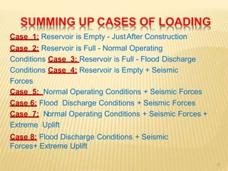
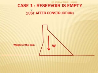
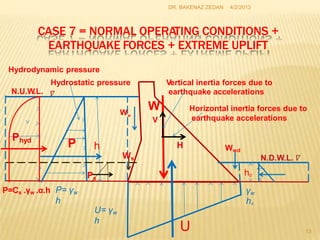
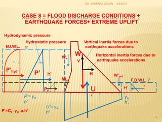
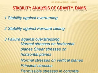
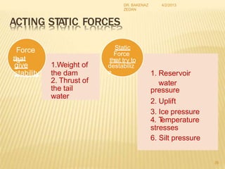
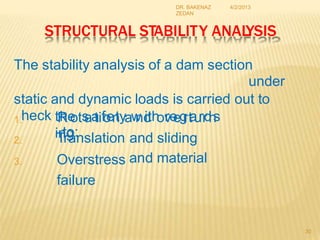
Gravity dams derive stability from their weight resisting overturning forces from reservoir water. Various loading cases are analyzed including empty, full, seismic, and flood conditions. Stability is checked against overturning, sliding, shear stresses and overstressing to ensure safety factors are not exceeded under different load combinations.
This document discusses the analysis of safety and stability for concrete gravity dams. It begins with an outline of the topics to be covered in Lecture 5, including a summary of loading cases, design of concrete gravity dams, safety analysis, and stability analysis. The document then provides detailed descriptions and diagrams for each of the 8 loading cases to be considered in the safety and stability analysis. It discusses the design of gravity dams and the procedures for analysis. Key aspects of the safety and stability analysis are described, including checking for overturning, sliding, shear stresses, and overstressing of the concrete. Diagrams are provided to illustrate the concepts of checking for overturning, sliding, and factors of safety.
This document presents an analysis of slope stability under rapid drawdown conditions and seismic loads for the Mandali Dam in Iraq. It uses the finite element software SLIDE V.6.0 to analyze the upstream slope stability during rapid drawdown from an operating water level of 182.5m to 172m. The analysis finds that the factor of safety decreases from 2.983 under normal conditions to 1.837 during rapid drawdown. Adding seismic loads of 0.07g further reduces the factor of safety to 1.376 and 1.254 for seismic loads in one and two directions, respectively. However, the upstream slope is found to remain stable even under these rapid drawdown and seismic conditions.
Comparison between static and dynamic analysis of elevated water tank 2IAEME Publication
The document compares the static and dynamic analysis of elevated water tanks. It aims to study the dynamic response of tanks using both analysis methods and to examine the effects of hydrodynamic pressure. Static analysis may provide considerably different responses than dynamic analysis for the same tank parameters. As tank capacity increases, so too does the difference between static and dynamic responses. Hydrodynamic pressure from water sloshing also affects tank response, with impulsive pressure typically greater for smaller tanks and convective pressure greater for larger tanks.
The document discusses using linear fluid viscous dampers to dissipate seismic energy in steel structures, summarizing how the dampers work by resisting force through piston movement in viscous fluid according to velocity. A study is presented analyzing the seismic response of a 12-story steel building with diagonal fluid viscous dampers subjected to earthquake accelerations, finding the dampers significantly improve the structure's dissipative capacity and reduce necessary steel quantities.
LECTURE 5 safety and stability analysis- modified-2Bakenaz A. Zeidan
This document discusses the analysis of safety and stability for concrete gravity dams. It begins with an outline of the lecture, which covers stability analysis, stress analysis, design criteria, and a solved example. The document then summarizes the 8 cases of loading considered in stability analysis, including empty, full, flood, and seismic loading conditions. It provides details on the design of gravity dams, including their weight-based stability and structural components. The document outlines the procedures for concrete gravity dam design and analysis of stability against overturning, sliding, shear stresses, and overstressing. Safety criteria and factors of safety are discussed.
This document provides information on analyzing the stability and safety of concrete gravity dams. It discusses the different loading cases to consider, including empty reservoir, full reservoir under normal and flood conditions, and with seismic forces. It describes analyzing the dam's stability against overturning, sliding, shear stresses, and foundation and concrete overstresses. The document outlines the assumptions made in stability analysis and the recommended safety factors. It also discusses determining normal and principal stresses in the dam, and ensuring compressive stresses are maintained.
This document provides an overview of the design and analysis of concrete gravity dams. It discusses the key components and layout of concrete gravity dams, as well as the design steps and expected loadings. The main loads considered include dead load, water pressure, uplift pressure, silt pressure, wave pressure, and earthquake loads. Formulas are provided for calculating each of these loads. The document also discusses factors like stability, stress analysis, and freeboard that are important considerations in the design of concrete gravity dams.
This document discusses forces acting on concrete gravity dams, including uplift pressure. Uplift pressure is an important force to consider in gravity dam design and safety, as it can compromise structural integrity, especially in cracked dams. The document outlines the traditional approach to modeling uplift pressure as varying linearly from full reservoir pressure at the base upstream to zero pressure downstream. It notes that a more conservative modern approach is to apply uplift pressure across the full base area. Proper consideration of uplift pressure is crucial for gravity dam safety evaluations and design.
This document discusses the various loads that act on a gravity dam. It identifies primary loads such as water load, self-weight, and uplift pressure as the major loads that are important for all dam types. Secondary loads like silt load, wave pressure, thermal load are also discussed. Exceptional loads include earthquake force, which exerts both vertical and horizontal components that must be designed for. The document provides details on calculating and accounting for these various dam loads in the planning and design of gravity dams.
Types of Gravity Dam
Forces Acting on a Gravity Dam
Causes of failure of Gravity Dam
Elementary Profile of Gravity Dam
Practical Profile of Gravity Dam
Limiting height of Gravity Dam
Drainage and Inspection Galleries
This document discusses gravity dams and earth dams. For gravity dams, it describes the typical cross-section and forces acting on the dam, including water pressure, dam weight, uplift pressure, and more. It also discusses potential failure modes like overturning, sliding, compression, and tension. For earth dams, it outlines the components including shells and cores, and failure causes such as hydraulic failure from overtopping, seepage failure, and structural failure from cracking or sliding. It provides details on preliminary sections for earth dams and criteria for their safe design.
This document provides an overview of the state of the art in design and analysis of concrete gravity dams. It discusses the key components of gravity dam design including introduction, types of loads, theoretical approaches, modeling techniques, analysis methods, and safety criteria. The presentation covers the basic definitions and properties of concrete gravity dams and their foundations. It also examines various analytical, experimental, and numerical modeling approaches used in the design process.
This document discusses stability evaluation techniques for staged construction projects involving soft cohesive soils, where controlled rates of loading are used. It reviews three types of stability analyses: total stress analysis, effective stress analysis, and undrained strength analysis. For staged construction, the key issue is what drainage condition is assumed during potential failure - drained or undrained. An effective stress analysis inherently assumes drained failure, but failures often occur undrained. The document argues undrained strength analysis is most appropriate for staged construction, as it accounts for changes in undrained shear strength during construction. Case histories are presented to illustrate the importance of the drainage assumption made. The document provides recommendations on conducting undrained strength analyses and monitoring field performance during staged construction.
Gravity dams are solid structures constructed of concrete or masonry across a river to create an upstream reservoir. They resist forces through their own weight distributed in a triangular cross-section. Forces on gravity dams include the weight of the dam, water pressure, uplift pressure, silt pressure, wave pressure, and earthquake forces. Dams are designed to withstand these forces through computation of vertical and horizontal force components and consideration of factors like reservoir level, foundation type, and seismic zone.
This lecture discusses building design considerations for resisting loads and natural hazards. It begins by outlining the objectives of understanding differential movement design and rational terms to resist phenomena like earthquakes, flooding, and meet user needs. Various loads that affect building design are then defined, including dead loads from building materials, live loads from occupants, and lateral loads from wind, snow, and earthquakes. The importance of structural stability and equilibrium is discussed. The lecture concludes by examining how building design factors like massing, floor plan complexity, and structural symmetry influence earthquake vulnerability.
1. A gravity dam is a solid structure made of concrete or masonry that is constructed across a river to create an upstream reservoir. It resists forces through its own weight and triangular cross-section, with the widest part at the bottom.
2. Forces acting on a gravity dam include water pressure, uplift pressure, earthquake forces, and the weight of the dam itself. Uplift pressure is caused by water seeping through the dam and its foundation.
3. Dams are designed to withstand these forces through their weight and cross-sectional shape. Additional design considerations include drainage systems to relieve uplift pressure, and seismic design using coefficients and response spectrum analysis for earthquake forces.
This document discusses the types of loads acting on concrete dams and the methods used for designing gravity dams. It describes primary loads like water pressure and self-weight, secondary loads like sediment and wind, and exceptional loads like seismic activity. It also covers load combinations, factors of safety against overturning and sliding, and considers the shear strength of the concrete and foundation. Design aims to satisfy equilibrium conditions and ensure stresses do not exceed allowable limits.
This document discusses the key forces acting on a gravity dam, including its weight, water pressure, uplift pressure, silt pressure, wave pressure, and earthquake forces. It defines key terms like structural height, maximum base width, and hydraulic height. It also provides details on how to calculate or estimate the various forces, for example explaining that water pressure acts normal to the face of the dam and can be calculated based on horizontal and vertical components. Uplift pressure is defined as the upward pressure of water seeping through the dam or its foundation. Earthquake forces cause random vibrations that impart accelerations to the dam's foundation.
Topics:
1. Types of Gravity Dam
2. Forces Acting on a Gravity Dam
3. Causes of failure of Gravity Dam
4. Elementary Profile of Gravity Dam
5. Practical Profile of Gravity Dam
6. Limiting height of Gravity Dam
7. Drainage and Inspection Galleries
This document discusses the forces acting on gravity dams and their environmental impacts. It outlines various forces like water pressure, weight of the dam, uplift pressure, earthquake pressure, and wave pressure. It also explains how these forces are calculated. Regarding failure, it notes dams can fail through overturning, sliding, compression, or tension. The document concludes by covering environmental impacts of dam construction like pollution, and impacts of reservoirs like habitat destruction and sedimentation.
Causes of settlement, foundation loading and computationPirpasha Ujede
This document discusses various types of settlement that can occur in foundations and soils due to applied loads. It describes immediate settlement (Si) due to soil distortion, primary consolidation settlement (Sc) due to pore pressure dissipation in clays, and secondary consolidation settlement (Ss) in organic soils. The total settlement (S) is the sum of these three components. It also outlines other causes of settlement like erosion, temperature changes, vibrations, and mining. The document concludes by defining and explaining the different types of design loads that cause settlement, including dead loads, live loads, wind loads, snow loads, earth pressures, water pressures, and earthquake loads.
This document discusses the various loads that act on concrete dams, including primary, secondary, and exceptional loads. It provides details on the following primary loads: water load, self-weight load, and seepage loads (internal and external uplift). Secondary loads discussed include sediment load, wave load, wind load, and ice load. Exceptional loads mentioned include seismic and tectonic effects. The document also contains schematic diagrams that illustrate how these loads are distributed on gravity dams and their points of application. Equations are provided for calculating the magnitudes of several load types.
Gravity dams resist forces through their own weight and come in masonry and concrete varieties. Key components include the crest, freeboard, heel, toe, sluice way, and drainage gallery. Dams are vulnerable to vibrations from earthquakes which can impact the dam body and reservoir. The largest danger occurs when vibrations are perpendicular to the dam face. Parameters like freeboard, top width, and base width are considered in the dam section design based on factors like roadway needs, uplift forces, and stability. Low and high gravity dams differ in how the resultant force passes through the base.
A gravity dam resists external forces through its own weight. It is a solid, durable structure constructed of masonry or concrete. Forces acting on a gravity dam include water pressure, the weight of the dam, uplift pressure, silt pressure, wave pressure, ice pressure, and pressure from earthquake forces. Water pressure is the major external force and varies with depth, while the weight of the dam is the main resisting force.
Review on seismic analysis of elevated water tank 2IAEME Publication
This document summarizes research on analyzing the seismic performance of elevated water tanks. It discusses how elevated water tanks are vulnerable to earthquakes due to their large mass concentrated at the top of slender supporting structures. Several past earthquakes resulted in collapsed or damaged water tanks due to unsuitable designs. The document reviews various studies on analyzing water tanks using static and dynamic methods, and accounting for factors like sloshing effects, hydrodynamic pressures, and flexible supports. It discusses recommendations to improve seismic provisions in building codes. The review indicates the importance of proper modeling and consideration of fluid-structure interaction for accurately evaluating the seismic response of elevated water tanks.
This document discusses the design and construction of gravity dams. It explains that gravity dams resist forces through their massive weight and have vertical or near-vertical faces. The key components, external forces, and methods of stress analysis are described. Failure can occur through sliding, overturning, cracking or crushing, so factors of safety are considered. Joints are used to aid construction and control cracking. High construction costs require stable foundations, but maintenance costs are lower with less water loss.
Design of-steel-structures bhavakkati- by easy engineering.netsaibabu48
The document contains repeated text blocks noting that content was downloaded from www.EasyEngineering.net. It requests that other websites or blogs do not copy or republish the materials and to report any instances of finding the same materials with the EasyEngineering watermark. The document provides attribution to EasyEngineering.net as the source but does not contain any other substantive content.
The document outlines the key terms of a lease agreement between John Doe as the landlord and Jane Smith as the tenant. It specifies the monthly rent amount and due date, the security deposit required, allows for pets but prohibits smoking, and describes the process for repairs, entry by the landlord, and early termination of the lease. The landlord and tenant must both sign the agreement prior to the tenant moving into the rental property.
This document provides information about structural steel materials and specifications used in steel structures. It discusses different grades of structural steel like IS 226, IS 2062, and IS 961. It also describes common rolled steel sections like I-sections, channel sections, angle sections, and their designations. Key concepts covered are materials properties, stress-strain curves, working stress method, limit state design method, analysis and design of steel structures. The document is intended as a reference for the design of steel structures course.
This document discusses tension members in structural engineering. It defines tension members as linear members that experience axial forces that elongate or stretch the member. Examples given include ropes, ties in trusses, suspenders in bridges. The document discusses the types of cross-sections used for tension members like angles, channels, rods. It also discusses the calculation of net effective sectional area and provides examples. Other topics covered include types of failures in tension members, design strength calculations, limiting slenderness ratios, tension splices, and lug angles.
This document contains a question bank for the subject of Design of Steel Structures. It includes multiple choice and numerical questions covering various topics in steel design such as bolted and welded connections, tension members, riveted joints, and limit state design approach. Some sample 16-mark design questions are provided related to designing tension members using angles, plates, and bolted/riveted connections to gusset plates to transmit axial forces. The document is intended as a study guide for students in the third year of a Civil Engineering program.
This document contains a question bank for a steel structures design course. It includes 20 questions in Part A testing basic knowledge of steel structures terminology and concepts. Part B contains 14 design problems testing application and evaluation skills. Topics covered include riveted and bolted connections, tension members, compression members, beams, plate girders, roof trusses, and crane girders. Students are asked to calculate strengths, suitable dimensions, and designs meeting loading criteria. Design factors like load magnitudes, member lengths, connection materials, and support conditions are provided.
The document contains 43 pages of lecture notes from Srividya College of Engineering and Technology on the design of steel structures. The notes cover various topics related to the design of tension members, compression members, and beams under the bending, shear, and axial forces. Design examples are included for the analysis and design of different steel structural elements.
1. The document discusses best practices for analyzing risks related to dam and levee spillway gates.
2. It describes different types of spillway gates and their vulnerabilities, including issues that led to the 1995 failure of Gate 3 at Folsom Dam in California due to trunnion pin friction.
3. Key factors that influence spillway gate risk are discussed, such as reservoir water level, seismic hazard, gate size, maintenance practices, and the potential for multiple gate failures. Event tree and fragility curve methods are presented for evaluating failure probabilities under different loading conditions.
Spillways are designed to safely pass excess water from a reservoir to prevent overtopping of a dam. They come in many forms depending on site conditions but commonly include an overflow structure like an ogee crest to control reservoir levels. Proper spillway capacity is essential for dam safety as inadequate capacity contributes to 40% of dam failures. Spillway design considers hydrologic factors, hydraulic performance including discharge coefficients, and structural aspects like cost-effectiveness. Gates may be added to overflows to allow flexible reservoir operation while preventing overtopping during floods.
The document provides information on diversion headworks for water resources engineering projects. It discusses the different types of diversion headworks including storage and temporary diversion structures. Key components of diversion headworks are described such as weirs, barrages, divide walls, fish ladders, and canal head regulators. Factors for selecting sites for diversion structures are outlined. Causes of failures for weirs built on permeable foundations and remedies are summarized.
1) Canals are artificial channels constructed to carry water from a source like a river or reservoir to agricultural fields.
2) Canals are classified based on their water source (permanent or inundation), function (irrigation, navigation, power), alignment (watershed, contour, side slope), discharge (main, branch, distributary), and whether they have lining.
3) The cross-section of a canal includes components like side slopes, berms, freeboard, banks, and may involve partial cutting and filling to achieve a balancing depth.
Canal lining involves adding an impermeable layer to canal beds and banks to reduce water seepage losses. Common lining materials include compacted earth, concrete, and plastic membranes. Lining can conserve up to 50% of irrigation water by preventing seepage and allowing canals to maintain higher water velocities using smaller cross-sections. It also stabilizes canal banks, prevents erosion, and increases the command area by allowing flatter canal slopes. Hard linings include cast concrete while earth linings use compacted soil or soil-bentonite mixes. Buried plastic membranes are another option but are susceptible to damage.
Spillways are structures constructed near dams to safely discharge surplus water from reservoirs. There are several types of spillways classified by their utility and prominent features. Main spillways are designed to pass the entire design flood volume, while auxiliary spillways supplement the main spillway. Emergency spillways activate only during emergencies. Common spillway types include overflow, which guides water smoothly over a curved crest; side channel, which diverts flow through a parallel channel; and tunnel, which conveys flow through a closed channel around the dam. Shaft spillways similarly direct water vertically then horizontally through a tunnel.
This document discusses different types of earth and rockfill dams. It describes rolled fill dams which are constructed by compacting soil in thin layers. Homogeneous dams consist of a single material throughout while zoned dams have distinct core, shell, and filter zones. Diaphragm dams contain an impervious core like a thin wall. Key elements of earth dam design include the top width, freeboard, slopes, central core, and downstream drainage system.
This document discusses different types of subsurface irrigation methods, including natural and artificial subsurface irrigation. Natural subsurface irrigation involves using the natural water table to irrigate crops through capillary action, while artificial subsurface irrigation uses buried perforated pipes to maintain the water table below the soil surface. The document also discusses sprinkler irrigation systems, how they work, their advantages of uniform water distribution and adaptability, and disadvantages like high costs and interference from wind. Finally, it defines and discusses drip irrigation, how it efficiently applies water directly to plant roots, and its advantages like water and fertilizer efficiency as well as disadvantages like sensitivity to clogging.
The document discusses different types of spillways used in dam construction including:
- Main and emergency spillways which provide controlled water release from dams.
- Straight (free overfall) spillways where water freely drops over the crest edge.
- Ogee spillways with an S-shaped crest profile that are commonly used in rigid dams.
- Side channel spillways which divert water away from the main dam through an adjacent channel.
- Chute spillways which lower water levels through steeply inclined channels.
- Tunnel spillways which pass water through underground tunnels.
- Siphon spillways which use siphonic action through enclosed conduits to discharge water downstream.
Spillways are structures used to release water from reservoirs to prevent overflow of dams. There are two main types of spillways: controlled and uncontrolled. Controlled spillways have gates to regulate water flow, while uncontrolled spillways release water once the reservoir level rises above the spillway crest. Spillways can also be classified based on their shape, such as ogee, side channel, labyrinth, chute, conduit, and baffled chute spillways. Each type has distinct hydraulic characteristics that make it suitable for different dam designs and site conditions.
This presentation discusses different types of spillways used in dam structures. Spillways are needed to safely discharge water from the reservoir during floods to prevent overtopping of the dam. The main types discussed are chute, shaft, saddle, and side channel spillways. Chute spillways convey water down an excavated open channel with a steep slope. Shaft spillways allow water to pass through a vertical shaft and horizontal conduit below the dam. Saddle spillways use natural depressions as spillway routes. Side channel spillways route flood water parallel to the dam.
This document discusses the design principles for retaining walls. It describes:
1) Different categories of retaining structures based on height, including curbs under 0.6m, short walls up to 3m using reinforcement, and taller walls requiring bracing.
2) Design considerations for stability of soils, the wall itself, structural strength, and effects on adjacent structures.
3) Basic loading factors including earth pressures, water pressures, and surcharges from loads or traffic.
4) Considerations for soil properties, selection of backfill material, and effects of groundwater.
The document describes four main methods of irrigation: surface irrigation, subsurface irrigation, sprinkler irrigation, and drip or trickle irrigation. Surface irrigation involves applying water to the soil surface through methods like flooding, furrows, borders, or basins. Subsurface irrigation applies water underground through trenches or pipes. Sprinkler irrigation sprays water into the air through nozzles, simulating rainfall. Drip irrigation delivers water slowly to the soil through a network of valves, pipes, tubing, and emitters. Each method has advantages and suitability for different crop and soil conditions.
Comfort & Clean Air Solution Authorized Corporate Sale & Service Dealer.
HVAC is an acronym for Heating, Ventilation, and Air Conditioning. The term HVAC is used to describe a complete home comfort system that can be used to heat and cool your home, as well as provide improved indoor air quality.
"Cold Call Campaigns Success visually represent data and information related to the effectiveness of cold calling in sales and marketing strategies. These graphics use a combination of charts, graphs, and illustrations to convey key insights and statistics in a concise and engaging manner.
The infographics may include data on conversion rates, lead generation, call-to-sale ratios, and other metrics to showcase the impact of cold calling on business growth. They can also highlight best practices, tips, and strategies for optimizing cold call campaigns to improve success rates.
By presenting complex information in a visually appealing format, these infographics make it easier for viewers to understand and digest the content quickly. This makes them an effective tool for businesses looking to communicate the benefits of cold calling and its role in driving sales success.
Overall, infographics on Cold Call Campaigns Success serve as a valuable resource for sales professionals, marketers, and business owners seeking to enhance their cold calling strategies and achieve greater success in their campaigns.
6. SUMMING UP CASES OF LOADING
Case 1: Reservoir is Empty - JustAfter Construction
Case 2: Reservoir is Full - Normal Operating
Conditions Case 3: Reservoir is Full - Flood Discharge
Conditions Case 4: Reservoir is Empty + Seismic
Forces
Case 5: Normal Operating Conditions + Seismic Forces
Case 6: Flood Discharge Conditions + Seismic Forces
Case 7: Normal Operating Conditions + Seismic Forces +
Extreme Uplift
Case 8: Flood Discharge Conditions + Seismic
Forces+ Extreme Uplift
6
7. DR. BAKENAZ ZEDAN 4/2/2013
CASE 1 : RESERVOIR IS EMPTY
(JUST AFTER CONSTRUCTION)
Weight of the dam
W
7
8. DR. BAKENAZ ZEDAN 4/2/2013
CASE 2
NORMAL
: RESERVOIR IS FULL
OPERATING CONDITIONS
Hydrostatic pressure
N.U.W.L.
W
Wwd
P Ws N.D.W.L.
Pd
U hd
γw
hd
s
P= γw
h
δ
U= γw
h
8
W
h
P
P
w
9. CASE 3 : RESERVOIR IS FULL
FLOOD DISCHARGE CONDITIONS
F
.U.W.L.
W
W’wd
Ws F
.D.W.L
P’d
U
’
h’d
γ
s
P’=
h’
γ
δ
w w
h’d
U’=
h’
γw
9
Hydrostatic pressure W
h'
P’
P
’w
10. CASE 4 = RESERVOIR IS EMPTY + SEISMIC FORCES
Vertical inertia forces due to
earthquake accelerations Horizontal inertia forces due to
earthquake accelerations
V
H
Weight of the dam
W
10
11. Pd
CASE 5 = NORMAL OPERATING CONDITIONS +
EARTHQUAKE FORCES
Hydrodynamic pressure
Hydrostatic pressure Vertical inertia forces due to
earthquake accelerations
N.U.W.L.
W
V
Horizontal inertia forces due to
earthquake accelerations
H Wwd
Ws
P= γw
h
γw
hd
P=Cs .γw .α.h
δ
U= γw
h
U
hd
Phyd
W
P h
w
Ps
12. P d
DR. BAKENAZ ZEDAN 4/2/2013
CASE 6 = FLOOD DISCHARGE CONDITIONS +
EARTHQUAKE FORCES
Hydrodynamic pressure
Hydrostatic pressure Vertical inertia forces due to
earthquake accelerations
F
.U.W.L.
W
V
Horizontal inertia forces due to
earthquake accelerations
H W’wd
Ws
s
d
P’= γw
h’
P’=Cs .γw .α.h’
γw
h’d
δ
U’=
h’
γw
U
’ 12
H’ ’
P’hyd
W
P’ h'
’w
P
13. Pd
DR. BAKENAZ ZEDAN 4/2/2013
CASE 7 = NORMAL OPERATING CONDITIONS +
EARTHQUAKE FORCES + EXTREME UPLIFT
Hydrodynamic pressure
Hydrostatic pressure Vertical inertia forces due to
earthquake accelerations
N.U.W.L.
W
V
Horizontal inertia forces due to
earthquake accelerations
H Wwd
Ws
P= γw
h
γw
hd
P=Cs .γw .α.h
U= γw
h
U 13
hd
Phyd
W
P h
w
Ps
14. P d
DR. BAKENAZ ZEDAN 4/2/2013
CASE 8 = FLOOD DISCHARGE CONDITIONS +
EARTHQUAKE FORCES+ EXTREME UPLIFT
Hydrodynamic pressure
Hydrostatic pressure Vertical inertia forces due to
earthquake accelerations
F
.U.W.L.
W
V
Horizontal inertia forces due to
earthquake accelerations
H W’wd
Ws
U d
’
P’= γw
h’
γw
h’d
U’= γw
h’
P’=Cs .γw .α.h’
14
H’ ’
P’hyd
W
P’ h'
’w
Ps
15. DR. BAKENAZ ZEDAN 4/2/2013
DESIGN OF GRAVITY DAMS
INTRODUCTION:
Dams are national properties, for the
development of national economy in which large
investments are deployed
Safety of dams is a very important aspect for
safeguarding national investmentand
benefits derived by the project
Unsafe dams constitute hazards to human life
in the downstream reaches
Safety of dams and allied structures is an
important aspect to be examined to ensure
public confidence and to protect downstream
area from any potential hazards.
15
16. DR. BAKENAZ ZEDAN 4/2/2013
DESIGN OF GRAVITY DAMS
T
echnically, a concrete gravity dam derives its
stability from the force of gravity of its materials.
The gravity dam has sufficient weight so as to
withstand the force and the over turning
moments caused by the water impounded in
the reservoir behind it.
It transfers the loads to the foundations by
cantilever action and hence good foundations
ar
e pre requisite for the gravity dam.
16
17. DR. BAKENAZ ZEDAN 4/2/2013
DESIGN OF GRAVITY DAMS
Gravity dams are satisfactorily adopted for narrow valleys
having
stiff geological formations.
Their own weight resists the forces exerted upon them.
They must have sufficient weight against overturning
tendency about the toe.
The base width of gravity dams must be large enough
prevent sliding.
These types of dams are susceptible to settlement,
overturning, sliding and severe earthquake shocks.
to
17
18. DR. BAKENAZ ZEDAN 4/2/2013
PROCEDURE OF CONCRETE GRAVITY DESIGN
In the gravity dam calculations one should proceed through the following
steps:
1determination of all expected acting loads
2 state the combination of acting loads for each case of loading
3check stability against overturning for all possible cases of loading (cases
of full reservoir)
4 check stability against forward sliding for all possible cases of loading
(cases
of full reservoir)
5determine normal stress distribution at dam base and any given sections
for all cases of loading
6determine maximum and minimum principal and shear stresses at
dam base and any given sections for all cases of loading
7compare results with corresponding factors of safety and allowable
stresses 8- approve the dam profile or redesign for a new profile
18
19. DR. BAKENAZ ZEDAN 4/2/2013
STABILITY CRITERIA
analyses are performed for various
loading conditions
Stability
The structure
stability
must prove its safety and
under all loading conditions.
Since the probability of occurrence of extreme events is
relatively small, the joint probability of the independent
extreme events is negligible. In other words, the
probability that two extreme events occur at the
same time is relatively very low.
Therefore, combination of extreme events are
not considered in the stability criteria.
e.g. Floods (spring and summer)
need to
versus Ice load
(winter). then no
at the
consider these
two forces same time. 19
20. DR. BAKENAZ ZEDAN 4/2/2013
STABILITY CRITERIA
Usual Loading
Hydrostatic force (normal operating
level) Uplift force
T
emperature stress
Dead
loads Ice
loads Silt
load
(normal temperature)
Unusual Loading Hydrostatic
force (reservoir full) Uplift
force
Stress produced by minimum
level Dead loads
Silt load
Extreme (severe) Loading
temperature at full
20
21. DR. BAKENAZ ZEDAN 4/2/2013
STABILITY CRITERIA
The ability of a dam to resist the applied loads
measured by some safety factors.
T
o offset the uncertainties in the loads, safety
is
criteria are chosen sufficiently
equilibrium condition.
Recommended safety factors:
1987)
However, since each dam site
beyond the static
(USBR, 1976 and
has unique features,
different safety Factors may be derived considering
the local condition.
21
22. DR. BAKENAZ ZEDAN 4/2/2013
STABILITY CRITERIA
F
.S0: Safety factor against overturning.
F
.Ss: Safety factor against sliding.
F
.Sss: Safety factor against shear and sliding.
22
23. DR. BAKENAZ ZEDAN 4/2/2013
STABILITY ANAL
YSIS OF GRAVITY DAMS
1 Stability against overturning
2 Stability against Forward sliding
3 Failure against overstressing
Normal stresses on horizontal
planes Shear stresses on
horizontal planes
Normal stresses on vertical planes
Principal stresses
Permissible stresses in concrete 23
24. DR. BAKENAZ
ZEDAN
4/2/2013
STABILITY ANAL
YSIS OF CONCRETE GRAVITY DAMS
For the considerations of stability of a concrete
gravity dam the following assumptions are made:
• Is composed of individual transverse vertical
elements each of which carries
foundation separately
its load to the
the
dam
• Is carried out for the whole
block
Stabilit
y
analysi
s
vertica
stress
• Varies linearly from upstream face to downstream
face on any horizontal section
l
24
25. DR. BAKENAZ
ZEDAN
4/2/2013
CLASSIFICA
TION OFLOADING FOR DESIGN
Normal Loads
They are those, under the combined action of which the dam shall have adequate
stability
, and the factors of safety and permissible stresses in the dam shall not be exceeded.
Abnormal Loads
These are the loads which in combination with normal loads encroach upon the factor of
safety and increase the allowable stresses although remaining lower than the higher emergency
stress limits.
25
Normal Loads Abnormal Loads
Water pressure corresponding to Higher water pressure during floods
full reservoir level.
Weight of dam and structure above it. Earthquake force
Uplift. Silt pressure
Wave pressure
Ice thrust
Thermal stresses
26. DR. BAKENAZ
ZEDAN
4/2/2013
ACTING STATIC FORCES
Static
Force
th
sat
Force
ths
at try to
give destabiliz
e
stability
water
26
1. Reservoir
pressure
2. Uplift
3. Ice pressure
4. T
emperature
stresses
6. Silt pressure
1.Weight of
the dam
2. Thrust of
the tail
water
27. DR. BAKENAZ
ZEDAN
4/2/2013
ACTING DYNAMIC FORCES
Dynami
Force
th
sat
c
th
Faotrtcre
ys
give d
to
estabiliz
e
stability
2.Hydrodynami
water
pressure
27
1.Seismic
forces
c pressure
3.Forces due
to waves in the
reservoir
4. Wind
1.Weight of
the dam
2. Thrust of
the tail
28. DR. BAKENAZ
ZEDAN
4/2/2013
SAFETY OF
CONCRETE
Equilibrium states that:
GRAVIT
Y
DA
M
∑FX=0, ∑FY=0, ∑M@ any
point=0 Should attained
otherwise
If
If
If
If
∑FX ≠ 0, forward sliding may occur
∑FY ≠ 0, settlement may occur
∑M ≠ 0 forward overturning may occur
eccentricity exceeds B/6 , tension forces may
occur If working stresses
than allowable stresses
greater
failure may occur due to excessive stresses or 28
29. DR. BAKENAZ
ZEDAN
4/2/2013
SAFETY OF CONCRETE GRAVITY
Thus a dam profile should be safe against:
DAM
forward sliding and translation
Settlement or tilting
1.
2.
forward overturning
T
ensile stresses
failure due to over
stresses Cracks &
material failure
or rotation
3.
4.
5.
6.
7.
Higher responses than allowable
limit
according to codes 29
30. DR. BAKENAZ
ZEDAN
4/2/2013
STRUCTURAL STABILITY ANAL
YSIS
The stability analysis of a dam section
under
static and dynamic loads is carried out to
1.heck
2.
tR
he
ots
aa
tifo
en
tyaw
nd
ith
ov
re
eg
rt
a
u
rr
d
n
s
in
tg
o:
Translation
Overstress
failure
and
and
sliding
material
3.
30
36. e,
DR. BAKENAZ ZEDAN
4/2/2013
SAFETY AGAINST FORWARD SLIDING
In the presence of a horizon with low
shear resistance the net shear force
may equal to:
(W cosα+ ∑Hsin α) tanφ
where W is the passive resistance wedg
α is the assumed angle of sliding failure,
∑H is the net de-stabilizing horizontal moment,
and φ is the internal friction within the rock at plane
B-B
36
39. DR. BAKENAZ
ZEDAN
4/2/2013
SAFETY AGAINST OVERSTRESSING
A dam may fail if any of its part is overstressed
and hence the stresses at any part of the dam
should not exceed the allowable working stress
concrete.
Hence the strength in dam concrete should be
of
more than the anticipated in the structure by a
margin
The maximum compressive stresses occur at:
safe
at heel (at reservoir empty condition)
or
and
at toe (at reservoir full condition)
on planes normal to the face of the dam. 39
40. DR. BAKENAZ
ZEDAN
4/2/2013
SAFETY AGAINST OVERSTRESSING
For design considerations, the calculation of
the stresses in the body of the dam follows
from the basics of elastic theory, which is
applied in two- dimensional vertical plane, and
assuming the block of the dam to be a
cantilever in the vertical plane attached to the
foundation.
The contact stress between the foundation
and the dam or the internal stress in the dam
body must be compressive. 40
41. DR. BAKENAZ ZEDAN
4/2/2013
SAFETY AGAINST CONCRETE OVERSTRESSING
∑V
B
σtoe
flexural stres σheel
Normal stress Bending or
s
Base pressure distribution
41
43. DR. BAKENAZ ZEDAN
4/2/2013
SAFETY AGAINST FOUNDATION OVERSTRESSING
AT DAM BASE
Naturally, there would be tension on the upstream face
if the overturning moments under the reservoir full
condition increase such that e becomes greater than
B/6. The total vertical stresses at the upstream and
downstream faces are obtained by addition of external
hydrostatic pressures.
The contact stress between the foundation and the
dam or the internal stress in the dam body must be
compressive. In order to maintain compressive
stresses in the dam or at the foundation level, the
minimum pressureσmin ≥0. This can be achieved with
rac
ne
gr
e
ta
o
in
f 43
45. DR. BAKENAZ
ZEDAN
STABILITY CRITERIA
4/2/2013
The contact stress between the foundation and the dam or the internal
stress in the dam body must be compressive:
T
ension along the upstream face of a gravity dam is possible under
operating conditions.
reservoir
z = 1.0 (if there is no drainage in the dam body)
z = 0.4 (if drains are used)
P: hydrostatic pressure at the level under consideration
45
46. DR.BAKENAZZEDA
N
4/2/201
3
Given data:
Crest width 1 0 m
Base width 50mHeight
of dam 60mHeight of
reservoir 55mTail water
height 0 m
Height of sedimentation 10m
Unit weight of concrete =24 KN/m3
Modulus of Elasticity= 28 MPa
Unit weight of water= 10 KN/m3
Unit weight of sedimentation =14 KN/m3
Seismic coefficient= 0.2
Required:
Check the stability of the dam profile
( q>= 30°)
46