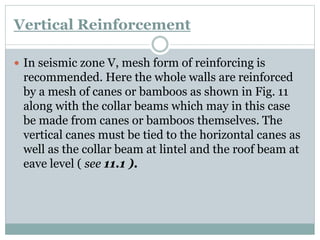
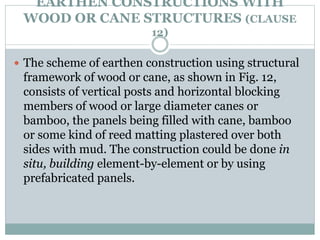
PRESENTED BY:-
ER. DIVYA
VISHNOI
IS 13827:1993 (SECOND REVISION)
IMPROVING EARTHQUAKE
RESISTANCE OF
EARTHEN BUILDINGS-
GUIDELINES
SCOPE:-
 The guidelines covered in this standard deal
with the design and construction aspects for
improving earthquake resistance of earthen
houses, without the use of stabilizers, such
as cement, lime, asphalt, admixtures, etc.
 The provisions of this standard are
applicable to all seismic zones ( see IS 1893
:1984 for seismic zones ).
DESCRIPTION OF CODE:-
 TERMINOLOGY
 GENERAL PRINCIPLES
 SPECIAL CONSTRUCTION FEATURES
 TYPES OF CONSTRUCTION
 CATEGORIES OF BUILDINGS
 MASONRY CONSTRUCTION WITH
RECTANGULAR MASONRY UNITS
 FLOORS/ROOFS WITH SMALL PRECAST
COMPONENTS
 TIMBER CONSTRUCTION
TERMINOLOGY:-
 ADOBE
 BOX ACTION
 BAND
 SEISMIC ZONE& SEISMIC COEFFICIENT
 ZONE FACTOR
GENERAL PRINCIPLES(CLAUSE 4.0)
 4.1 For the safety of earthen houses, appropriate precautions must be
taken against the actions of rain and flood waters and earthquakes.
Minimum precautions are recommended in this standard.
 4.2 Whereas dry clay block is hard and strong in compression and
shear, water penetration will make it soft and weak, the reduction in
strength could be as high as 80 to 90 percent. Hence, once built, ingress of
moisture in the walls must be prevented by the protection, roof projection
and waterproof mud plastering.
 4.3 These recommendations are low-cost and do not include the
use of stabilizers, which are rather costly though effective in increasing the
strength and water-resistance of the clay units or walls. Where feasible
time-stabilized compacted clay blocks or cement-stabilized sandy soil
blocks may be used with compatible stronger mortars.
 LIGHTNESS
 HEIGHT
 SHAPE OF BUILDING
CONSTRUCTION OF EARTHEN WALL
(CLAUSE 5.0)
 5.0 Earthen walls may be constructed in the following four ways.
 5.1 Hand-formed in layers using mud-lumps to form walls.
 5.2 Built by using sun-dried blocks or adobe which may be cut from
hardened soil, or formed in moulds, or moulded and compacted and
laid in courses using clay mud as mortar.
 5.3 Built by using rammed earth (Pise or Tapial) in which moist soil
is filled between wall forms and compacted manually or
mechanically.
 5.4 Constructed using wood, bamboo or cane structure with wood,
bamboo, cane or ikra mesh enclosures plastered with mud ( Assam
type construction ).
 5.5 Whereas systems 5.1, 5.2 and 5.3 depend on the strength of
earthen walls for stability, the system 5.4 behaves like wood frame
and its construction has been dealt with under 12.
SUITABILITY OF SOIL (CLAUSE 6.0)
 The following qualitative tests may be used for
determining the suitability of a soil for earthen
construction.
 1. Dry Strength Test
 2. Fissure Control Test
 3. Strength Test of Adobe
 4. The compressive strength may be determined by
testing 100 mm cubes of clay after completely drying
them. A minimum value of 1.2 N/mm2 will be
desirable.
 HAND-FORMED LAYERED CONSTRUCTION
 BLOCK OR ADOBE CONSTRUCTION
 RAMMED EARTH CONSTRUCTION
HAND-FORMED LAYERED
CONSTRUCTION (CLAUSE 7.0)
 7.1 Walls built by hand-forming are the most primitive
and weakest of all earthen walls, since enough moisture for
full dispersion of clay is not usually employed, yet fissures also
develop horizontally and vertically. Use of straw is
recommended in the clay, so as to impart strength and
reduction of fissures.
 7.2 The quality of construction will improve if the clay-
water-straw mixture was allowed to rest for 7 days (minimum
3 days) before use in walls so that thorough dispersion of
moisture in clay and decomposition of straw into fibres takes
place.
 7.3 The area of the lower layer should be moistened
well before adding the new layer so as to minimize the
horizontal fissures at the joints.
RECOMMENDATIONS FOR SEISMIC AREAS
(CLAUSE 10)
 1. Walls:-
 10.1.1 The height of the adobe building should be restricted to
one storey plus attic only in seismic zones V and IV and to two
storeys in other zones. Important building (I ≥ 1.5) should not
be constructed with earthen walls in seismic zones IV and V
and restricted to only one storey in seismic other zones.
 10.1.2 The length of a wall, between two consecutive walls at
right angles to it, should not be greater than 10 times the wall
thickness t nor greater than 64 t2/h where h is the height of
wall ( see Fig. 4 ).
 10.1.3 When a longer wall is required, the walls should be
strengthened by intermediate vertical buttresses ( see Fig. 4 ).
 10.1.4 The height of wall should not be greater than 8 times its
thickness ( see Fig. 4 ).
RECOMMENDATIONS FOR SEISMIC AREAS
(CLAUSE 10)
 10.1.5 The width of an opening should not be greater
than 1.20 m ( see Fig. 5 ).
 10.1.6 The distance between an outside corner and the
opening should be not less than 1.20 m.
 10.1.7 The sum of the widths of openings in a wall should
not exceed percent the total wall length in seismic zone V
and 40 percent in zones IV and III and 50 percent in
zone II.
 10.1.8 The bearing length (embedment) of lintels on each
side of an opening should not be less than 300 mm. For
an adequate configuration for an earthen house, see 10.5.
RECOMMENDATIONS FOR SEISMIC AREAS
(CLAUSE 10)
 10.1.9 Hand-formed walls could preferably be made
tapering upwards keeping the minimum thickness
300 mm at top and increasing it with a batter of 1 :
12 at bottom ( see Fig. 4b ).
 10.1.10 Providing outside pillasters at all corners and
junctions of walls are recommended as these
increase the seismic stability of the buildings a great
deal ( see Fig. 5 ).
 10.1.11 Special seismic strengthening featurers may
be done as specified in 11.
RECOMMENDATIONS FOR SEISMIC AREAS
(CLAUSE 10)
 2. House Site:-
 10.2.1 Sites with sandy loose soils, poorly compacted clays,
and fill materials should generally be discarded due to their
excessive settlements during seismic vibrations. Also, sites
with very high water table should be avoided. These
recommendations are particularly important for seismic
zones V and IV.
 10.2.2 Site shall be above high flood level or the ground
shall be raised to this effect.
RECOMMENDATIONS FOR SEISMIC AREAS
(CLAUSE 10)
 3. Foundation:-
 10.3.1 Width of strip footings of the walls may
 be kept as follows:
i) One storey on firm soil— Equal to wallthickness
ii) 1.5 or 2 storeys on firmsoil— 1.5 times thewall thickness
iii) One storey on soft soil — 1.5 times thewall thickness
iv) 1.5 or 2 storeys on soft soil—2 times the wall thickness.
 10.3.2 The depth of foundation below existing ground level should
at least be 400 mm.
 10.3.3 The footing should preferably be built by using stone, fired
brick using cement or lime mortar. Alternatively, it may be made in
lean cement concrete with plums (cement : sand : gravel : stones as
1 : 4 : 6 : 10) or without plums as 1 : 5 : 10. Lime could be used in
place of cement in the ratio lime : sand : gravel as 1 : 4 : 8.
 4. Roof: -
 10.4.1 The roofing structure must be light, wellconnected and adequately
tied to the walls. Trusses are superior to sloping roofs consisting of only rafters or A
frames.
 10.4.2 The roof covering should preferably be of light material, like sheeting
of any type. Heavy roofs consisting of wood joists and earth topping are dangerous
and should not be used in Zones V and IV. Tiled and slate roofs are also heavier and
shall be avoided in zones V and IV.
 10.4.3 If thatch is used for roof covering, it should better be made waterproof
and fireresistant by applying waterproof mud plaster ( see 13.3 ).
 10.4.4 The roof beams, rafters or trusses should preferably be rested on
longitudinal wooden elements for distributing the load on walls.
 10.4.5 The slopes and the overhanging will depend on local climatic
conditions. In zones subjected to rain and snow, walls protection must be ensured
by projecting the roof by about 500 mm beyond the walls ( see Fig. 6 ).
 10.4.6 The roof beams or rafters should be located to avoid their position
above door or window lintels. Otherwise, the lintel should be reinforced by an
additional lumber ( see Fig. 7 ).
 5. Adequate Configuration:-
 Summarizing most of the recommendations
contained in this standard, a configuration is shown
in Fig. 8 which will, in general, be adequate for
seismic areas including zone V and IV. Additional
seismic strengthening features are presented in 12.
SEISMIC STRENGTHENING OF BEARING
WALL BUILDINGS
 1. Collar beam or Horizontal Reinforcement
 2. Pillasters and Buttresses
 3. Vertical Reinforcement
Collar Beam or Horizontal Band
 Two horizontal continuous reinforcing and binding beams or bands should
be placed, one coinciding with lintels of door and window opening, and the
other just below the roof in all walls in seismic zones III, IV and V. Only
one such band either below the roof or at the lintel level may be used in
zone II. Proper connection of ties placed at right angles at the corners and
junctions of walls should be ensured. Where the height of wall is not more
than 2.5 m, the lintel band can be avoided, but the lintels should be
connected to the roof band ( see 11.2 ).
 The bands could be in the following forms:
a) Unfinished rough cut or sawn (70 ×150 mm in section) lumber in single
pieces provided diagonal members for bracing at corners ( see Fig. 9a ).
b) Unfinished rough cut or sawn (50 ×100 mm or 70 × 70 mm in section)
lumber two pieces in parallel with halved joints at corners and junctions of
walls placed in parallel ( see Fig. 9b ).
 In each case, the lengthening joint in the elements shall be made using
iron-straps with sufficient nails/screws to ensure the strength of the
original lumber at the joint.
Pillasters and Buttresses
 Where pillasters or buttresses are used, as
recommended earlier at corner or T-junctions, the
collar beam should cover the buttresses as well, as
shown in Fig. 10. Use of diagonal struts at corners
will further stiffen the collar beam.
Vertical Reinforcement
 In seismic zone V, mesh form of reinforcing is
recommended. Here the whole walls are reinforced
by a mesh of canes or bamboos as shown in Fig. 11
along with the collar beams which may in this case
be made from canes or bamboos themselves. The
vertical canes must be tied to the horizontal canes as
well as the collar beam at lintel and the roof beam at
eave level ( see 11.1 ).
EARTHEN CONSTRUCTIONS WITH
WOOD OR CANE STRUCTURES (CLAUSE
12)
 The scheme of earthen construction using structural
framework of wood or cane, as shown in Fig. 12,
consists of vertical posts and horizontal blocking
members of wood or large diameter canes or
bamboo, the panels being filled with cane, bamboo
or some kind of reed matting plastered over both
sides with mud. The construction could be done in
situ, building element-by-element or by using
prefabricated panels.
PLASTERING AND PAINTING (CLAUSE
13)
 The purpose of plastering and painting is to give
protection and durability to the walls and thatch
roof, in addition to obvious aesthetic reasons.
IS 13827

IS 13827

  • 1.
    PRESENTED BY:- ER. DIVYA VISHNOI IS13827:1993 (SECOND REVISION) IMPROVING EARTHQUAKE RESISTANCE OF EARTHEN BUILDINGS- GUIDELINES
  • 2.
    SCOPE:-  The guidelinescovered in this standard deal with the design and construction aspects for improving earthquake resistance of earthen houses, without the use of stabilizers, such as cement, lime, asphalt, admixtures, etc.  The provisions of this standard are applicable to all seismic zones ( see IS 1893 :1984 for seismic zones ).
  • 3.
    DESCRIPTION OF CODE:- TERMINOLOGY  GENERAL PRINCIPLES  SPECIAL CONSTRUCTION FEATURES  TYPES OF CONSTRUCTION  CATEGORIES OF BUILDINGS  MASONRY CONSTRUCTION WITH RECTANGULAR MASONRY UNITS  FLOORS/ROOFS WITH SMALL PRECAST COMPONENTS  TIMBER CONSTRUCTION
  • 4.
    TERMINOLOGY:-  ADOBE  BOXACTION  BAND  SEISMIC ZONE& SEISMIC COEFFICIENT  ZONE FACTOR
  • 5.
    GENERAL PRINCIPLES(CLAUSE 4.0) 4.1 For the safety of earthen houses, appropriate precautions must be taken against the actions of rain and flood waters and earthquakes. Minimum precautions are recommended in this standard.  4.2 Whereas dry clay block is hard and strong in compression and shear, water penetration will make it soft and weak, the reduction in strength could be as high as 80 to 90 percent. Hence, once built, ingress of moisture in the walls must be prevented by the protection, roof projection and waterproof mud plastering.  4.3 These recommendations are low-cost and do not include the use of stabilizers, which are rather costly though effective in increasing the strength and water-resistance of the clay units or walls. Where feasible time-stabilized compacted clay blocks or cement-stabilized sandy soil blocks may be used with compatible stronger mortars.  LIGHTNESS  HEIGHT  SHAPE OF BUILDING
  • 6.
    CONSTRUCTION OF EARTHENWALL (CLAUSE 5.0)  5.0 Earthen walls may be constructed in the following four ways.  5.1 Hand-formed in layers using mud-lumps to form walls.  5.2 Built by using sun-dried blocks or adobe which may be cut from hardened soil, or formed in moulds, or moulded and compacted and laid in courses using clay mud as mortar.  5.3 Built by using rammed earth (Pise or Tapial) in which moist soil is filled between wall forms and compacted manually or mechanically.  5.4 Constructed using wood, bamboo or cane structure with wood, bamboo, cane or ikra mesh enclosures plastered with mud ( Assam type construction ).  5.5 Whereas systems 5.1, 5.2 and 5.3 depend on the strength of earthen walls for stability, the system 5.4 behaves like wood frame and its construction has been dealt with under 12.
  • 7.
    SUITABILITY OF SOIL(CLAUSE 6.0)  The following qualitative tests may be used for determining the suitability of a soil for earthen construction.  1. Dry Strength Test  2. Fissure Control Test  3. Strength Test of Adobe  4. The compressive strength may be determined by testing 100 mm cubes of clay after completely drying them. A minimum value of 1.2 N/mm2 will be desirable.
  • 8.
     HAND-FORMED LAYEREDCONSTRUCTION  BLOCK OR ADOBE CONSTRUCTION  RAMMED EARTH CONSTRUCTION
  • 9.
    HAND-FORMED LAYERED CONSTRUCTION (CLAUSE7.0)  7.1 Walls built by hand-forming are the most primitive and weakest of all earthen walls, since enough moisture for full dispersion of clay is not usually employed, yet fissures also develop horizontally and vertically. Use of straw is recommended in the clay, so as to impart strength and reduction of fissures.  7.2 The quality of construction will improve if the clay- water-straw mixture was allowed to rest for 7 days (minimum 3 days) before use in walls so that thorough dispersion of moisture in clay and decomposition of straw into fibres takes place.  7.3 The area of the lower layer should be moistened well before adding the new layer so as to minimize the horizontal fissures at the joints.
  • 10.
    RECOMMENDATIONS FOR SEISMICAREAS (CLAUSE 10)  1. Walls:-  10.1.1 The height of the adobe building should be restricted to one storey plus attic only in seismic zones V and IV and to two storeys in other zones. Important building (I ≥ 1.5) should not be constructed with earthen walls in seismic zones IV and V and restricted to only one storey in seismic other zones.  10.1.2 The length of a wall, between two consecutive walls at right angles to it, should not be greater than 10 times the wall thickness t nor greater than 64 t2/h where h is the height of wall ( see Fig. 4 ).  10.1.3 When a longer wall is required, the walls should be strengthened by intermediate vertical buttresses ( see Fig. 4 ).  10.1.4 The height of wall should not be greater than 8 times its thickness ( see Fig. 4 ).
  • 11.
    RECOMMENDATIONS FOR SEISMICAREAS (CLAUSE 10)  10.1.5 The width of an opening should not be greater than 1.20 m ( see Fig. 5 ).  10.1.6 The distance between an outside corner and the opening should be not less than 1.20 m.  10.1.7 The sum of the widths of openings in a wall should not exceed percent the total wall length in seismic zone V and 40 percent in zones IV and III and 50 percent in zone II.  10.1.8 The bearing length (embedment) of lintels on each side of an opening should not be less than 300 mm. For an adequate configuration for an earthen house, see 10.5.
  • 12.
    RECOMMENDATIONS FOR SEISMICAREAS (CLAUSE 10)  10.1.9 Hand-formed walls could preferably be made tapering upwards keeping the minimum thickness 300 mm at top and increasing it with a batter of 1 : 12 at bottom ( see Fig. 4b ).  10.1.10 Providing outside pillasters at all corners and junctions of walls are recommended as these increase the seismic stability of the buildings a great deal ( see Fig. 5 ).  10.1.11 Special seismic strengthening featurers may be done as specified in 11.
  • 13.
    RECOMMENDATIONS FOR SEISMICAREAS (CLAUSE 10)  2. House Site:-  10.2.1 Sites with sandy loose soils, poorly compacted clays, and fill materials should generally be discarded due to their excessive settlements during seismic vibrations. Also, sites with very high water table should be avoided. These recommendations are particularly important for seismic zones V and IV.  10.2.2 Site shall be above high flood level or the ground shall be raised to this effect.
  • 14.
    RECOMMENDATIONS FOR SEISMICAREAS (CLAUSE 10)  3. Foundation:-  10.3.1 Width of strip footings of the walls may  be kept as follows: i) One storey on firm soil— Equal to wallthickness ii) 1.5 or 2 storeys on firmsoil— 1.5 times thewall thickness iii) One storey on soft soil — 1.5 times thewall thickness iv) 1.5 or 2 storeys on soft soil—2 times the wall thickness.  10.3.2 The depth of foundation below existing ground level should at least be 400 mm.  10.3.3 The footing should preferably be built by using stone, fired brick using cement or lime mortar. Alternatively, it may be made in lean cement concrete with plums (cement : sand : gravel : stones as 1 : 4 : 6 : 10) or without plums as 1 : 5 : 10. Lime could be used in place of cement in the ratio lime : sand : gravel as 1 : 4 : 8.
  • 15.
     4. Roof:-  10.4.1 The roofing structure must be light, wellconnected and adequately tied to the walls. Trusses are superior to sloping roofs consisting of only rafters or A frames.  10.4.2 The roof covering should preferably be of light material, like sheeting of any type. Heavy roofs consisting of wood joists and earth topping are dangerous and should not be used in Zones V and IV. Tiled and slate roofs are also heavier and shall be avoided in zones V and IV.  10.4.3 If thatch is used for roof covering, it should better be made waterproof and fireresistant by applying waterproof mud plaster ( see 13.3 ).  10.4.4 The roof beams, rafters or trusses should preferably be rested on longitudinal wooden elements for distributing the load on walls.  10.4.5 The slopes and the overhanging will depend on local climatic conditions. In zones subjected to rain and snow, walls protection must be ensured by projecting the roof by about 500 mm beyond the walls ( see Fig. 6 ).  10.4.6 The roof beams or rafters should be located to avoid their position above door or window lintels. Otherwise, the lintel should be reinforced by an additional lumber ( see Fig. 7 ).
  • 16.
     5. AdequateConfiguration:-  Summarizing most of the recommendations contained in this standard, a configuration is shown in Fig. 8 which will, in general, be adequate for seismic areas including zone V and IV. Additional seismic strengthening features are presented in 12.
  • 17.
    SEISMIC STRENGTHENING OFBEARING WALL BUILDINGS  1. Collar beam or Horizontal Reinforcement  2. Pillasters and Buttresses  3. Vertical Reinforcement
  • 18.
    Collar Beam orHorizontal Band  Two horizontal continuous reinforcing and binding beams or bands should be placed, one coinciding with lintels of door and window opening, and the other just below the roof in all walls in seismic zones III, IV and V. Only one such band either below the roof or at the lintel level may be used in zone II. Proper connection of ties placed at right angles at the corners and junctions of walls should be ensured. Where the height of wall is not more than 2.5 m, the lintel band can be avoided, but the lintels should be connected to the roof band ( see 11.2 ).  The bands could be in the following forms: a) Unfinished rough cut or sawn (70 ×150 mm in section) lumber in single pieces provided diagonal members for bracing at corners ( see Fig. 9a ). b) Unfinished rough cut or sawn (50 ×100 mm or 70 × 70 mm in section) lumber two pieces in parallel with halved joints at corners and junctions of walls placed in parallel ( see Fig. 9b ).  In each case, the lengthening joint in the elements shall be made using iron-straps with sufficient nails/screws to ensure the strength of the original lumber at the joint.
  • 19.
    Pillasters and Buttresses Where pillasters or buttresses are used, as recommended earlier at corner or T-junctions, the collar beam should cover the buttresses as well, as shown in Fig. 10. Use of diagonal struts at corners will further stiffen the collar beam.
  • 20.
    Vertical Reinforcement  Inseismic zone V, mesh form of reinforcing is recommended. Here the whole walls are reinforced by a mesh of canes or bamboos as shown in Fig. 11 along with the collar beams which may in this case be made from canes or bamboos themselves. The vertical canes must be tied to the horizontal canes as well as the collar beam at lintel and the roof beam at eave level ( see 11.1 ).
  • 21.
    EARTHEN CONSTRUCTIONS WITH WOODOR CANE STRUCTURES (CLAUSE 12)  The scheme of earthen construction using structural framework of wood or cane, as shown in Fig. 12, consists of vertical posts and horizontal blocking members of wood or large diameter canes or bamboo, the panels being filled with cane, bamboo or some kind of reed matting plastered over both sides with mud. The construction could be done in situ, building element-by-element or by using prefabricated panels.
  • 22.
    PLASTERING AND PAINTING(CLAUSE 13)  The purpose of plastering and painting is to give protection and durability to the walls and thatch roof, in addition to obvious aesthetic reasons.