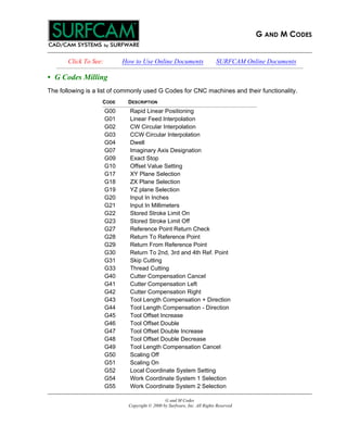
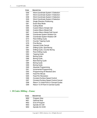
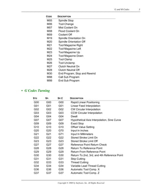
G AND M CODES
G and M Codes
Copyright © 2000 by Surfware, Inc. All Rights Reserved
Click To See: How to Use Online Documents SURFCAM Online Documents
G AND M CODES
• G Codes Milling
The following is a list of commonly used G Codes for CNC machines and their functionality.
CODE DESCRIPTION
G00 Rapid Linear Positioning
G01 Linear Feed Interpolation
G02 CW Circular Interpolation
G03 CCW Circular Interpolation
G04 Dwell
G07 Imaginary Axis Designation
G09 Exact Stop
G10 Offset Value Setting
G17 XY Plane Selection
G18 ZX Plane Selection
G19 YZ plane Selection
G20 Input In Inches
G21 Input In Millimeters
G22 Stored Stroke Limit On
G23 Stored Stroke Limit Off
G27 Reference Point Return Check
G28 Return To Reference Point
G29 Return From Reference Point
G30 Return To 2nd, 3rd and 4th Ref. Point
G31 Skip Cutting
G33 Thread Cutting
G40 Cutter Compensation Cancel
G41 Cutter Compensation Left
G42 Cutter Compensation Right
G43 Tool Length Compensation + Direction
G44 Tool Length Compensation - Direction
G45 Tool Offset Increase
G46 Tool Offset Double
G47 Tool Offset Double Increase
G48 Tool Offset Double Decrease
G49 Tool Length Compensation Cancel
G50 Scaling Off
G51 Scaling On
G52 Local Coordinate System Setting
G54 Work Coordinate System 1 Selection
G55 Work Coordinate System 2 Selection
2 G and M Codes
Copyright © 2000 by Surfware, Inc. All Rights Reserved
• M Codes Milling - Fanuc
G56 Work Coordinate System 3 Selection
G57 Work Coordinate System 4 Selection
G58 Work Coordinate System 5 Selection
G59 Work Coordinate System 6 Selection
G60 Single Direction Positioning
G61 Exact Stop Mode
G64 Cutting Mode
G65 Custom Macro Simple Call
G66 Custom Macro Modal Call
G67 Custom Macro Modal Call Cancel
G68 Coordinate System Rotation On
G69 Coordinate System Rotation Off
G73 Peck Drilling Cycle
G74 Counter Tapping Cycle
G76 Fine Boring
G80 Canned Cycle Cancel
G81 Drilling Cycle, Spot Boring
G82 Drilling Cycle, Counter Boring
G83 Peck Drilling Cycle
G84 Tapping Cycle
G85 Boring Cycle
G86 Boring Cycle
G87 Back Boring Cycle
G88 Boring Cycle
G89 Boring Cycle
G90 Absolute Programming
G91 Incremental Programming
G92 Programming Of Absolute Zero
G94 Feed Per Minute
G95 Feed Per Revolution
G96 Constant Surface Speed Control
G97 Constant Surface Speed Control Cancel
G98 Return To Initial Point In Canned Cycles
G99 Return To R Point In Canned Cycles
CODE DESCRIPTION
M00 Program Stop
M01 Optional Stop
M02 End of Program
M03 Spindle On CW
M04 Spindle On CCW
CODE DESCRIPTION
Copyright © 2000 by Surfware, Inc. All Rights Reserved
G and M Codes 3
• G Codes Turning
M05 Spindle Stop
M06 Tool Change
M07 Mist Coolant On
M08 Flood Coolant On
M09 Coolant Off
M19 Spindle Orientation On
M20 Spindle Orientation Off
M21 Tool Magazine Right
M22 Tool Magazine Left
M23 Tool Magazine Up
M24 Tool Magazine Down
M25 Tool Clamp
M26 Tool Unclamp
M27 Clutch Neutral On
M28 Clutch Neutral Off
M30 End Program, Stop and Rewind
M98 Call Sub Program
M99 End Sub Program
STD SP. SP.C DESCRIPTION
G00 G00 G00 Rapid Linear Positioning
G01 G01 G01 Linear Feed Interpolation
G02 G02 G02 CW Circular Interpolation
G03 G03 G03 CCW Circular Interpolation
G04 G04 G04 Dwell
G07 G07 G07 Hypothetical Axis Interpolation, Sine Curve
G09 G09 G09 Exact Stop
G10 G10 G10 Offset Value Setting
G20 G20 G70 Input In Inches
G21 G21 G71 Input In Millimeters
G22 G22 G22 Stored Stroke Limit On
G23 G23 G23 Stored Stroke Limit Off
G27 G27 G27 Reference Point Return Check
G28 G28 G28 Return To Reference Point
G29 G29 G29 Return From Reference Point
G30 G30 G30 Return To 2nd, 3rd, and 4th Reference Point
G31 G31 G31 Skip Cutting
G32 G33 G33 Thread Cutting
G34 G34 G34 Variable Lead Thread Cutting
G36 G36 G36 Automatic Tool Comp. X
G37 G37 G37 Automatic Tool Comp. Z
CODE DESCRIPTION
4 G and M Codes
Copyright © 2000 by Surfware, Inc. All Rights Reserved
G40 G40 G40 Tool Nose Rad. Comp. Cancel
G41 G41 G41 Tool Nose Radius Comp. Left
G42 G42 G42 Tool Nose Radius Comp. Right
G50 G92 G92 Programming Of Absolute Zero
G65 G65 G65 User Macro Simple Call
G66 G66 G66 User Macro Modal Call
G67 G67 G67 User Macro Modal Call Cancel
G68 G68 G68 Mirror Image For Double Turrets On
G69 G69 G69 Mirror Image For Double Turrets Off
G70 G70 G72 Finishing Cycle
G71 G71 G73 Stock Removal, Turning
G72 G72 G74 Stock Removal, Facing
G73 G73 G75 Repeat Pattern
G74 G74 G76 Peck Drilling, Z Axis
G75 G75 G77 Grooving, X Axis
G76 G76 G78 Thread Cutting Cycle
G90 G77 G20 Cutting Cycle A
G92 G78 G21 Thread Cutting Cycle
G94 G79 G24 Cutting Cycle B
G96 G96 G96 Constant Surface Speed Control
G97 G97 G97 Constant Surface Speed Cancel
G98 G94 G94 Feed Per Minute
G99 G95 G95 Feed Per Revolution
G90 G90 Absolute Programming
G91 G91 Incremental Programming
STD SP. SP.C DESCRIPTION

G and m codes

  • 1.
    G AND MCODES G and M Codes Copyright © 2000 by Surfware, Inc. All Rights Reserved Click To See: How to Use Online Documents SURFCAM Online Documents G AND M CODES • G Codes Milling The following is a list of commonly used G Codes for CNC machines and their functionality. CODE DESCRIPTION G00 Rapid Linear Positioning G01 Linear Feed Interpolation G02 CW Circular Interpolation G03 CCW Circular Interpolation G04 Dwell G07 Imaginary Axis Designation G09 Exact Stop G10 Offset Value Setting G17 XY Plane Selection G18 ZX Plane Selection G19 YZ plane Selection G20 Input In Inches G21 Input In Millimeters G22 Stored Stroke Limit On G23 Stored Stroke Limit Off G27 Reference Point Return Check G28 Return To Reference Point G29 Return From Reference Point G30 Return To 2nd, 3rd and 4th Ref. Point G31 Skip Cutting G33 Thread Cutting G40 Cutter Compensation Cancel G41 Cutter Compensation Left G42 Cutter Compensation Right G43 Tool Length Compensation + Direction G44 Tool Length Compensation - Direction G45 Tool Offset Increase G46 Tool Offset Double G47 Tool Offset Double Increase G48 Tool Offset Double Decrease G49 Tool Length Compensation Cancel G50 Scaling Off G51 Scaling On G52 Local Coordinate System Setting G54 Work Coordinate System 1 Selection G55 Work Coordinate System 2 Selection
  • 2.
    2 G andM Codes Copyright © 2000 by Surfware, Inc. All Rights Reserved • M Codes Milling - Fanuc G56 Work Coordinate System 3 Selection G57 Work Coordinate System 4 Selection G58 Work Coordinate System 5 Selection G59 Work Coordinate System 6 Selection G60 Single Direction Positioning G61 Exact Stop Mode G64 Cutting Mode G65 Custom Macro Simple Call G66 Custom Macro Modal Call G67 Custom Macro Modal Call Cancel G68 Coordinate System Rotation On G69 Coordinate System Rotation Off G73 Peck Drilling Cycle G74 Counter Tapping Cycle G76 Fine Boring G80 Canned Cycle Cancel G81 Drilling Cycle, Spot Boring G82 Drilling Cycle, Counter Boring G83 Peck Drilling Cycle G84 Tapping Cycle G85 Boring Cycle G86 Boring Cycle G87 Back Boring Cycle G88 Boring Cycle G89 Boring Cycle G90 Absolute Programming G91 Incremental Programming G92 Programming Of Absolute Zero G94 Feed Per Minute G95 Feed Per Revolution G96 Constant Surface Speed Control G97 Constant Surface Speed Control Cancel G98 Return To Initial Point In Canned Cycles G99 Return To R Point In Canned Cycles CODE DESCRIPTION M00 Program Stop M01 Optional Stop M02 End of Program M03 Spindle On CW M04 Spindle On CCW CODE DESCRIPTION
  • 3.
    Copyright © 2000by Surfware, Inc. All Rights Reserved G and M Codes 3 • G Codes Turning M05 Spindle Stop M06 Tool Change M07 Mist Coolant On M08 Flood Coolant On M09 Coolant Off M19 Spindle Orientation On M20 Spindle Orientation Off M21 Tool Magazine Right M22 Tool Magazine Left M23 Tool Magazine Up M24 Tool Magazine Down M25 Tool Clamp M26 Tool Unclamp M27 Clutch Neutral On M28 Clutch Neutral Off M30 End Program, Stop and Rewind M98 Call Sub Program M99 End Sub Program STD SP. SP.C DESCRIPTION G00 G00 G00 Rapid Linear Positioning G01 G01 G01 Linear Feed Interpolation G02 G02 G02 CW Circular Interpolation G03 G03 G03 CCW Circular Interpolation G04 G04 G04 Dwell G07 G07 G07 Hypothetical Axis Interpolation, Sine Curve G09 G09 G09 Exact Stop G10 G10 G10 Offset Value Setting G20 G20 G70 Input In Inches G21 G21 G71 Input In Millimeters G22 G22 G22 Stored Stroke Limit On G23 G23 G23 Stored Stroke Limit Off G27 G27 G27 Reference Point Return Check G28 G28 G28 Return To Reference Point G29 G29 G29 Return From Reference Point G30 G30 G30 Return To 2nd, 3rd, and 4th Reference Point G31 G31 G31 Skip Cutting G32 G33 G33 Thread Cutting G34 G34 G34 Variable Lead Thread Cutting G36 G36 G36 Automatic Tool Comp. X G37 G37 G37 Automatic Tool Comp. Z CODE DESCRIPTION
  • 4.
    4 G andM Codes Copyright © 2000 by Surfware, Inc. All Rights Reserved G40 G40 G40 Tool Nose Rad. Comp. Cancel G41 G41 G41 Tool Nose Radius Comp. Left G42 G42 G42 Tool Nose Radius Comp. Right G50 G92 G92 Programming Of Absolute Zero G65 G65 G65 User Macro Simple Call G66 G66 G66 User Macro Modal Call G67 G67 G67 User Macro Modal Call Cancel G68 G68 G68 Mirror Image For Double Turrets On G69 G69 G69 Mirror Image For Double Turrets Off G70 G70 G72 Finishing Cycle G71 G71 G73 Stock Removal, Turning G72 G72 G74 Stock Removal, Facing G73 G73 G75 Repeat Pattern G74 G74 G76 Peck Drilling, Z Axis G75 G75 G77 Grooving, X Axis G76 G76 G78 Thread Cutting Cycle G90 G77 G20 Cutting Cycle A G92 G78 G21 Thread Cutting Cycle G94 G79 G24 Cutting Cycle B G96 G96 G96 Constant Surface Speed Control G97 G97 G97 Constant Surface Speed Cancel G98 G94 G94 Feed Per Minute G99 G95 G95 Feed Per Revolution G90 G90 Absolute Programming G91 G91 Incremental Programming STD SP. SP.C DESCRIPTION