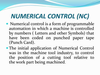
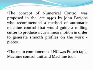
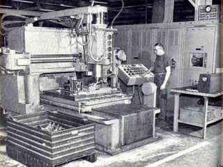
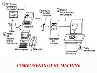
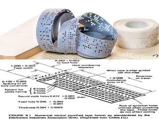
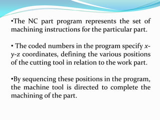
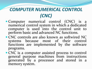
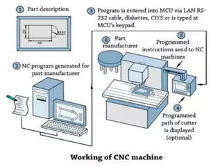
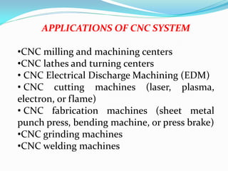
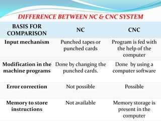
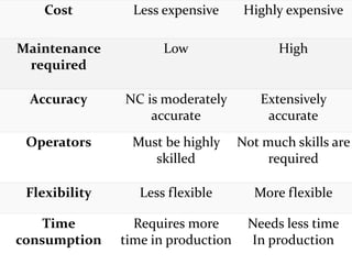
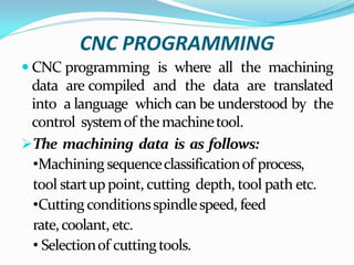
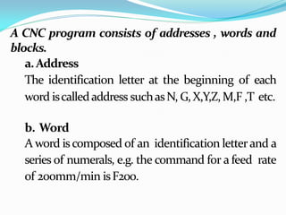
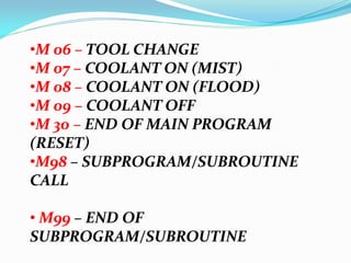
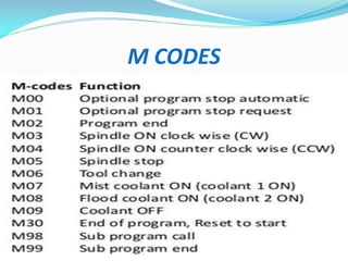
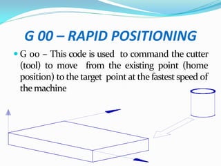
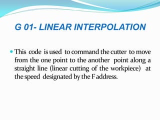
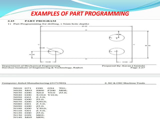
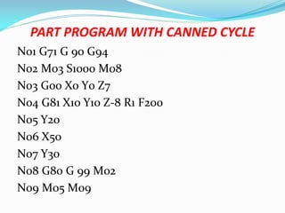
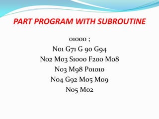
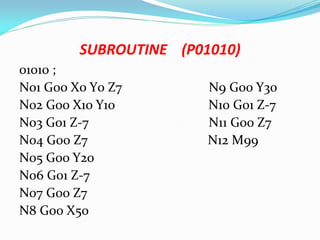
TOPIC – CNC PROGRAMMING
FACULTY
MD SHADAB REZA
UNIT – 2
DEPARTMENT OF SCIENCE & TECHNOLOGY
GOVERNMENT POLYTECHNIC PURNEA
DEPARTMENT OF MECHANICAL ENGINEERING
NUMERICAL CONTROL (NC)
 Numerical control is a form of programmable
automation in which a machine is controlled
by numbers ( Letters and other Symbols) that
have been coded on punched paper tape
(Punch Card).
 The initial application of Numerical Control
was in the machine tool industry, to control
the position of a cutting tool relative to
the work part being machined.
•The concept of Numerical Control was
proposed in the late 1940s by John Parsons
who recommended a method of automatic
machine control that would guide a milling
cutter to produce a curvilinear motion in order
to generate smooth profiles on the work -
pieces .
•The main components of NC was Punch tape,
Machine control unit and Machine tool.
COMPONENTS OF NC MACHINE
•The NC part program represents the set of
machining instructions for the particular part.
• The coded numbers in the program specify x-
y-z coordinates, defining the various positions
of the cutting tool in relation to the work part.
•By sequencing these positions in the program,
the machine tool is directed to complete the
machining of the part.
ADVANTAGES OF NC SYSTEM OVER
TRADITIONAL METHODS OF PRODUCTION
 Better control of the tool motion under
optimum cutting conditions.
 Improved part quality and repeatability.
 Reduced tooling costs, tool wear, and job
setup time.
 Reduced time to manufacture parts.
 Reduced scrap.
 Better production planning.
DISADVANTAGES OF NC SYSTEM
 The main disadvantage of the NC system was,
there is no any facility for error correction in
programming.
 If there is any small change in the machining
process is required, then the entire set of
Punch tape has to be changed.
 Punch tape can be used only for one time,
because NC system has no any memory unit.
 It was less flexible and more time consuming
in comparison with CNC system.
DIRECT NUMERICAL CONTROL (DNC)
 In a Direct Numerical Control system
(DNC), a mainframe computer is used to
coordinate the simultaneous operations of a
number of NC machines.
 The main tasks performed by the computer
are to program and edit part programs as
well as download part programs to NC
machines
•Machine tool controllers have limited
memory and a part program may contain few
thousands of blocks.
•So the program is stored in a separate
computer and sent directly to the machine,
one block at a time.
COMPUTER NUMERICAL CONTROL
(CNC)
 Computer numerical control (CNC) is a
numerical control system in which a dedicated
computer is used into the control unit to
perform basic and advanced NC functions.
 CNC controls are also known as softwired NC
systems because most of their control
functions are implemented by the software
programs.
 CNC is a computer assisted process to control
general purpose machines from instructions
generated by a processor and stored in a
memory system.
APPLICATIONS OF CNC SYSTEM
•CNC milling and machining centers
•CNC lathes and turning centers
• CNC Electrical Discharge Machining (EDM)
• CNC cutting machines (laser, plasma,
electron, or flame)
• CNC fabrication machines (sheet metal
punch press, bending machine, or press brake)
•CNC grinding machines
•CNC welding machines
BASIS FOR
COMPARISON
NC CNC
Input mechanism Punched tapes or
punched cards
Program is fed with
the help of the
computer
Modification in the
machine programs
Done by changing the
punched cards.
Done by using a
computer software
Error correction Not possible Possible
Memory to store
instructions
Not available Memory storage is
present in the
computer
DIFFERENCE BETWEEN NC & CNC SYSTEM
Cost Less expensive Highly expensive
Maintenance
required
Low High
Accuracy NC is moderately
accurate
Extensively
accurate
Operators Must be highly
skilled
Not much skills are
required
Flexibility Less flexible More flexible
Time
consumption
Requires more
time in production
Needs less time
In production
CNC PROGRAMMING
 CNC programming is where all the machining
data are compiled and the data are translated
into a language which can be understood by the
control systemof themachinetool.
The machining data is as follows:
•Machining sequenceclassificationof process,
tool startuppoint, cutting depth, tool path etc.
•Cutting conditionsspindlespeed, feed
rate,coolant, etc.
• Selectionof cuttingtools.
A CNC program consists of addresses , words and
blocks.
a.Address
The identification letter at the beginning of each
word iscalledaddress suchasN, G,X,Y,Z,M,F ,T etc.
b. Word
A word iscomposed of an identification letterand a
series of numerals, e.g. the command for a feed rate
of 200mm/min isF200.
c.Block
• Ablock iscomposedof oneormorewords.
• Acommand giventothecontrol unit iscalled
ablock.
FUNCTION
Sequencenumber
Preparatoryfunction
Coordinate Letter
ParametersforCircular
Interpolation
Feed function
Spindlefunction
Tool function
Miscellaneous function
N
G
X,Y,Z
I,J,K
F
S
T
M
ADDRESS
SEQUENCE NUMBER (N ADDRESS)
•A sequence number is used to identify the
block.
•It is always placed at the beginning of the block
andcanberegardedasthenameof theblock.
•It is program line number. Eg: N01, N02…
•It is a good practice to increment each
block number by 5 to 10 to allow additional
blocks to be inserted if future changes are
required. Eg – N05, N10….
•A preparatory function determines how the
tool isto movetotheprogrammed target.
•Preparatory function ,used as a
communication device to command the
MCU.
•The most common G addresses are listed
above.
PREPARATORY FUNCTION
(G ADDRESS OR G CODES)
G CODES
 G 00 – RAPID POSITIONING (RAPID
TRAVERSE)
 G 01 – LINEAR INTERPOLATION
 G 02 – CIRCULAR INTERPOLATION
CLOCKWISE (CW)
 G 03 - CIRCULAR INTERPOLATION
COUNTER CLOCKWISE (CCW)
 G 04 - DWELL
• G 17 - XY PLANE SELECTION
• G 18 – XZ PLANE SELECTION
• G 19 - YZ PLANE SELECTION
• G 20/70 - DIMENSIONING IN INCHES
• G 21/71 - DIMENSIONING IN
MILLIMETER (MM)
•G 40 – TOOL RADIUS COMPENSATION
CANCEL
• G 41 - TOOL RADIUS COMPENSATION
LEFT
•
•G 42 - TOOL RADIUS COMPENSATION
RIGHT
•G 80 – CANNED CYCLE CANCEL
•G 81 – 89 – CANNED CYCLE
• G 90 - ABSOLUTE DIMENSIONING
• G 91 - INCREMENTAL DIMENSIONING
• G 92 – PRESET (HOME)
• G 94 – FEED IN MM/MINUTE
• G 95 – FEED IN MM/REVOLUTION
CO-ORDINATE WORD
(X/Y/Z ADDRESS)
•A co-ordinate word specifies the target point of
thetool movement(absolute dimension system)
or the distance to be moved (incremental
dimension).
•The word is composed of the address of the axis
to be moved and the value and direction of the
movement.
EXAMPLE
X100 Y200 Z-10
•Represents the movement of tool to the co-
ordinates (100, 200,-10)ontheworkpiece.
•Whether the dimensions are absolute or
incremental will have to be defined previously
(using G90orG91).
PARAMETER FOR CIRCULAR
INTERPOLATION
(I/J/K ADDRESS)
•Theseparametersspecifythedistancemeasured
from thestartpointof thearc tothecentre.
• Numeralsfollowing I, Jand KaretheX, Yand Z
componentsof the distancerespectively.
SPINDLE FUNCTION
(S ADDRESS)
•The spindle speed iscommanded under anS
address .
•It isalways in revolution perminute.
•Eg – S1000
FEED FUNCTION
(F ADDRESS)
•The feed is programmed under an F address
exceptforrapid traverse.
•Theunit may be in mm per minute (in the case
of milling machine) or in mmper revolution(in
thecaseof turning machine).
•The unit of the feed rate has to be defined at
thebeginningof theprogram.
TOOL FUNCTION
T ADDRESS
 Tool selection.
 The T code specifies which tool is to be used
in a specific operation.
 Example: T02 - representstool number 2
MISCELLANEOUS FUNCTION
(M ADDRESS / CODES)
 Themiscellaneous function is programmed to
controlthemachineoperation otherthanfor
co-ordinate movement.
 Themostcommon M functions are listedabove:
M CODES
 M 00 - PROGRAM STOP
 M 01 – PLANNED STOP
 M02 – END OF PROGRAM
 M 03 – SPINDLE ROTATION CLOCKWISE
 M 04 – SPINDLE ROTATION ANTI -
CLOCKWISE
 M 05 – SPINDLE STOP
•M 06 – TOOL CHANGE
•M 07 – COOLANT ON (MIST)
•M 08 – COOLANT ON (FLOOD)
•M 09 – COOLANT OFF
•M 30 – END OF MAIN PROGRAM
(RESET)
•M98 – SUBPROGRAM/SUBROUTINE
CALL
• M99 – END OF
SUBPROGRAM/SUBROUTINE
M CODES
G 00 – RAPID POSITIONING
 G 00 – This code is used to command the cutter
(tool) to move from the existing point (home
position) to the target point at the fastest speed of
themachine
G 01- LINEAR INTERPOLATION
 This code isused tocommand thecutter to move
from the one point to the another point along a
straight line (linear cutting of the workpiece) at
thespeed designated bytheFaddress.
G02/G03 – CIRCULAR INTERPOLATION
 These codes are used to command the cutter to
move from the one point to the another point
along a circular arc either in clockwise direction
(G02)or incounterclockwise direction (G03).
 In this case, along with the target point, the radius
orthecentreof thearcisalso required.
 The parameters of the centre of the circular arc is
designated by the I, J and K addresses. I is the
distance along the X axis, Jalong the Y, and K along
theZ.
(Xc,Yc)
End point
Y I
J
Startpoint
(Xs,Ys)
X
FIG – G 02 - CIRCULARINTERPOLATION- CLOCKWISE
I (XC - XS)
J (YC - YS)
(Xc,Yc)
Startpoint
(Xs,Ys)
Endpoint
Y I
J
X
FIG – G 03- CIRCULAR INTERPOLATION -
COUNTERCLOCKWISE
G17G 17 G18 G19 :
PLANE SELECTIONG
G 17 : XY PLANE SELECTION
G 18 : XZ PLANE SELECTION
G 19 : YZ PLANE SELECTION
(G40/G41/G42)
CUTTER RADIUS COMPENSATION
 Cutter compensation is an offset or shift from
center line of the tools to the cutters edge along a
programmed path.
 The advantage of cutter compensation is the use
of geometry based offsets rather than tool center
point, allowing for the same program to use
different diameter tools.
•If thecutterison theleftof thecontour, G41 is
used.
•If thecutterison theright of thecontour, G42will
beused.
•G40 istocancelthecompensationcalculation.
G 70/20,G 71/21 –
DIMENSIONING IN INCHES & MM
G 90, G 91 –
ABSOLUTE & INCREMENTAL DIMENSIONING
G 90 A.D
G 91 – INCREMENTAL DIMENSIONING
EXAMPLES OF PART PROGRAMMING
PART PROGRAM FOR DRILLING
N01 G71 G 90 G94 N11 G01 Z-7
N02 M03 S1000 F200 M08 N12 G00 Z7
N03 G00 X0 Y0 Z7 N13 G00 Y30
N04 G00 X10 Y10 N14 G01 Z-7
N05 G01 Z-7 N15 G00 Z7
N06 G00 Z7 N16 G92 M05 M09
N07 G00 Y20 N17 M02
N08 G01 Z-7
N09 G00 Z7
N10 G00 X50
(G 80-89) - CANNED CYCLE
 A canned cycle is a combination of machine
movements that perform machining
operation like drilling, milling, boring and
tapping.
 This cycle simplifies the program by using a
single block with a G-code to specify the
machining operations usually specified in
several blocks.
 This cycle is also called as fixed cycle
• In programming point to point operation, to
write the repetitive information is very time
consuming task.
• This can be overcome by using the fixed
cycles, here once the drilling cycle is called
,then the only one step required i:e - to input
the position of holes .
• The machine controller repeats the drilling
cycle until it is cancelled by the G 80 code.
•A number of identical holes may share the
same starting point, same feed rate and the
same depth, only the X and Y coordinates are
different for each hole on the part.
•The specified values become fixed for the
whole duration of the cycle and do not have to
be repeated, unless there is a change in them.
http://www.helmancnc.com
(G 80-89)CANNED CYCLE
 G80 - Cancel Canned cycle
 G81 - Drilling cycle
 G82 - Drilling cycle with dwell
 G83 – Peck (Deep hole) drilling cycle
 G84 - Tapping cycle
 G85 – G 89 Boring cycle
G 81 – DRILLING CYCLE
SYNTAX FOR G 81
 G81 X... Y... Z... R... K... F...
Where….
 X Hole position in x-axis.
 Y Hole position in y-axis.
 Z Depth, tool will travel with feed to Z-
depth.
 R Position of the R plane.
 K Number of cycle repetitions (if required)
 F Feed rate.
Working
Here is briefly described how G81 drilling cycle operates,
1- Rapid traverse to the specified x,y axis position (drilling position).
2- Rapid traverse to the R plane position.
3- Drilling with specified Feed from R-plane position to Z-depth position.
4- Rapid traverse to Initial level or R-plane depends on G98, G99 modes
PART PROGRAM WITH CANNED CYCLE
N01 G71 G 90 G94
N02 M03 S1000 M08
N03 G00 X0 Y0 Z7
N04 G81 X10 Y10 Z-8 R1 F200
N05 Y20
N06 X50
N07 Y30
N08 G80 G 99 M02
N09 M05 M09
SUBROUTINES
 Subroutines or subprograms or mini-
programs are a powerful time saving
technique.
 The subroutine provide the capability of
programming certain fixed sequence or
frequently repeated patterns.
 Subroutines are actually an independent
program with all the features of a usual part
program.
• Subroutines are stored in the memory under
separates program number.
• Whenever a particular feature is required
within the program the associated subroutine
is called for execution.
• The subroutine may be called any time and
repeated any numbers of time.
•After execution of subroutines the control
return to main program.
•To describe and use a subroutine, the
following information is required in the form
of codes and symbols.
Calling the subroutine (M 98)
Identification of subroutine (by subroutine
ID, Eg – P1010)
Repetition of subroutine (by using letter L)
End of subroutine/ Return to main program
(M 99)
PART PROGRAM WITH SUBROUTINE
01000 ;
N01 G71 G 90 G94
N02 M03 S1000 F200 M08
N03 M98 P01010
N04 G92 M05 M09
N05 M02
SUBROUTINE (P01010)
01010 ;
N01 G00 X0 Y0 Z7 N9 G00 Y30
N02 G00 X10 Y10 N10 G01 Z-7
N03 G01 Z-7 N11 G00 Z7
N04 G00 Z7 N12 M99
N05 G00 Y20
N06 G01 Z-7
N07 G00 Z7
N8 G00 X50

CNC PROGRAMMING.pdf

  • 1.
    TOPIC – CNCPROGRAMMING FACULTY MD SHADAB REZA UNIT – 2 DEPARTMENT OF SCIENCE & TECHNOLOGY GOVERNMENT POLYTECHNIC PURNEA DEPARTMENT OF MECHANICAL ENGINEERING
  • 2.
    NUMERICAL CONTROL (NC) Numerical control is a form of programmable automation in which a machine is controlled by numbers ( Letters and other Symbols) that have been coded on punched paper tape (Punch Card).  The initial application of Numerical Control was in the machine tool industry, to control the position of a cutting tool relative to the work part being machined.
  • 3.
    •The concept ofNumerical Control was proposed in the late 1940s by John Parsons who recommended a method of automatic machine control that would guide a milling cutter to produce a curvilinear motion in order to generate smooth profiles on the work - pieces . •The main components of NC was Punch tape, Machine control unit and Machine tool.
  • 5.
  • 8.
    •The NC partprogram represents the set of machining instructions for the particular part. • The coded numbers in the program specify x- y-z coordinates, defining the various positions of the cutting tool in relation to the work part. •By sequencing these positions in the program, the machine tool is directed to complete the machining of the part.
  • 9.
    ADVANTAGES OF NCSYSTEM OVER TRADITIONAL METHODS OF PRODUCTION  Better control of the tool motion under optimum cutting conditions.  Improved part quality and repeatability.  Reduced tooling costs, tool wear, and job setup time.  Reduced time to manufacture parts.  Reduced scrap.  Better production planning.
  • 10.
    DISADVANTAGES OF NCSYSTEM  The main disadvantage of the NC system was, there is no any facility for error correction in programming.  If there is any small change in the machining process is required, then the entire set of Punch tape has to be changed.  Punch tape can be used only for one time, because NC system has no any memory unit.  It was less flexible and more time consuming in comparison with CNC system.
  • 11.
    DIRECT NUMERICAL CONTROL(DNC)  In a Direct Numerical Control system (DNC), a mainframe computer is used to coordinate the simultaneous operations of a number of NC machines.  The main tasks performed by the computer are to program and edit part programs as well as download part programs to NC machines
  • 13.
    •Machine tool controllershave limited memory and a part program may contain few thousands of blocks. •So the program is stored in a separate computer and sent directly to the machine, one block at a time.
  • 14.
    COMPUTER NUMERICAL CONTROL (CNC) Computer numerical control (CNC) is a numerical control system in which a dedicated computer is used into the control unit to perform basic and advanced NC functions.  CNC controls are also known as softwired NC systems because most of their control functions are implemented by the software programs.  CNC is a computer assisted process to control general purpose machines from instructions generated by a processor and stored in a memory system.
  • 16.
    APPLICATIONS OF CNCSYSTEM •CNC milling and machining centers •CNC lathes and turning centers • CNC Electrical Discharge Machining (EDM) • CNC cutting machines (laser, plasma, electron, or flame) • CNC fabrication machines (sheet metal punch press, bending machine, or press brake) •CNC grinding machines •CNC welding machines
  • 17.
    BASIS FOR COMPARISON NC CNC Inputmechanism Punched tapes or punched cards Program is fed with the help of the computer Modification in the machine programs Done by changing the punched cards. Done by using a computer software Error correction Not possible Possible Memory to store instructions Not available Memory storage is present in the computer DIFFERENCE BETWEEN NC & CNC SYSTEM
  • 18.
    Cost Less expensiveHighly expensive Maintenance required Low High Accuracy NC is moderately accurate Extensively accurate Operators Must be highly skilled Not much skills are required Flexibility Less flexible More flexible Time consumption Requires more time in production Needs less time In production
  • 19.
    CNC PROGRAMMING  CNCprogramming is where all the machining data are compiled and the data are translated into a language which can be understood by the control systemof themachinetool. The machining data is as follows: •Machining sequenceclassificationof process, tool startuppoint, cutting depth, tool path etc. •Cutting conditionsspindlespeed, feed rate,coolant, etc. • Selectionof cuttingtools.
  • 20.
    A CNC programconsists of addresses , words and blocks. a.Address The identification letter at the beginning of each word iscalledaddress suchasN, G,X,Y,Z,M,F ,T etc. b. Word A word iscomposed of an identification letterand a series of numerals, e.g. the command for a feed rate of 200mm/min isF200.
  • 21.
    c.Block • Ablock iscomposedofoneormorewords. • Acommand giventothecontrol unit iscalled ablock.
  • 24.
  • 25.
    SEQUENCE NUMBER (NADDRESS) •A sequence number is used to identify the block. •It is always placed at the beginning of the block andcanberegardedasthenameof theblock. •It is program line number. Eg: N01, N02… •It is a good practice to increment each block number by 5 to 10 to allow additional blocks to be inserted if future changes are required. Eg – N05, N10….
  • 26.
    •A preparatory functiondetermines how the tool isto movetotheprogrammed target. •Preparatory function ,used as a communication device to command the MCU. •The most common G addresses are listed above. PREPARATORY FUNCTION (G ADDRESS OR G CODES)
  • 27.
    G CODES  G00 – RAPID POSITIONING (RAPID TRAVERSE)  G 01 – LINEAR INTERPOLATION  G 02 – CIRCULAR INTERPOLATION CLOCKWISE (CW)  G 03 - CIRCULAR INTERPOLATION COUNTER CLOCKWISE (CCW)  G 04 - DWELL
  • 28.
    • G 17- XY PLANE SELECTION • G 18 – XZ PLANE SELECTION • G 19 - YZ PLANE SELECTION • G 20/70 - DIMENSIONING IN INCHES • G 21/71 - DIMENSIONING IN MILLIMETER (MM)
  • 29.
    •G 40 –TOOL RADIUS COMPENSATION CANCEL • G 41 - TOOL RADIUS COMPENSATION LEFT • •G 42 - TOOL RADIUS COMPENSATION RIGHT •G 80 – CANNED CYCLE CANCEL •G 81 – 89 – CANNED CYCLE
  • 30.
    • G 90- ABSOLUTE DIMENSIONING • G 91 - INCREMENTAL DIMENSIONING • G 92 – PRESET (HOME) • G 94 – FEED IN MM/MINUTE • G 95 – FEED IN MM/REVOLUTION
  • 31.
    CO-ORDINATE WORD (X/Y/Z ADDRESS) •Aco-ordinate word specifies the target point of thetool movement(absolute dimension system) or the distance to be moved (incremental dimension). •The word is composed of the address of the axis to be moved and the value and direction of the movement.
  • 32.
    EXAMPLE X100 Y200 Z-10 •Representsthe movement of tool to the co- ordinates (100, 200,-10)ontheworkpiece. •Whether the dimensions are absolute or incremental will have to be defined previously (using G90orG91).
  • 33.
    PARAMETER FOR CIRCULAR INTERPOLATION (I/J/KADDRESS) •Theseparametersspecifythedistancemeasured from thestartpointof thearc tothecentre. • Numeralsfollowing I, Jand KaretheX, Yand Z componentsof the distancerespectively.
  • 34.
    SPINDLE FUNCTION (S ADDRESS) •Thespindle speed iscommanded under anS address . •It isalways in revolution perminute. •Eg – S1000
  • 35.
    FEED FUNCTION (F ADDRESS) •Thefeed is programmed under an F address exceptforrapid traverse. •Theunit may be in mm per minute (in the case of milling machine) or in mmper revolution(in thecaseof turning machine). •The unit of the feed rate has to be defined at thebeginningof theprogram.
  • 36.
    TOOL FUNCTION T ADDRESS Tool selection.  The T code specifies which tool is to be used in a specific operation.  Example: T02 - representstool number 2
  • 37.
    MISCELLANEOUS FUNCTION (M ADDRESS/ CODES)  Themiscellaneous function is programmed to controlthemachineoperation otherthanfor co-ordinate movement.  Themostcommon M functions are listedabove:
  • 38.
    M CODES  M00 - PROGRAM STOP  M 01 – PLANNED STOP  M02 – END OF PROGRAM  M 03 – SPINDLE ROTATION CLOCKWISE  M 04 – SPINDLE ROTATION ANTI - CLOCKWISE  M 05 – SPINDLE STOP
  • 39.
    •M 06 –TOOL CHANGE •M 07 – COOLANT ON (MIST) •M 08 – COOLANT ON (FLOOD) •M 09 – COOLANT OFF •M 30 – END OF MAIN PROGRAM (RESET) •M98 – SUBPROGRAM/SUBROUTINE CALL • M99 – END OF SUBPROGRAM/SUBROUTINE
  • 40.
  • 41.
    G 00 –RAPID POSITIONING  G 00 – This code is used to command the cutter (tool) to move from the existing point (home position) to the target point at the fastest speed of themachine
  • 42.
    G 01- LINEARINTERPOLATION  This code isused tocommand thecutter to move from the one point to the another point along a straight line (linear cutting of the workpiece) at thespeed designated bytheFaddress.
  • 43.
    G02/G03 – CIRCULARINTERPOLATION  These codes are used to command the cutter to move from the one point to the another point along a circular arc either in clockwise direction (G02)or incounterclockwise direction (G03).  In this case, along with the target point, the radius orthecentreof thearcisalso required.  The parameters of the centre of the circular arc is designated by the I, J and K addresses. I is the distance along the X axis, Jalong the Y, and K along theZ.
  • 44.
    (Xc,Yc) End point Y I J Startpoint (Xs,Ys) X FIG– G 02 - CIRCULARINTERPOLATION- CLOCKWISE I (XC - XS) J (YC - YS)
  • 45.
    (Xc,Yc) Startpoint (Xs,Ys) Endpoint Y I J X FIG –G 03- CIRCULAR INTERPOLATION - COUNTERCLOCKWISE
  • 46.
    G17G 17 G18G19 : PLANE SELECTIONG G 17 : XY PLANE SELECTION
  • 47.
    G 18 :XZ PLANE SELECTION G 19 : YZ PLANE SELECTION
  • 48.
    (G40/G41/G42) CUTTER RADIUS COMPENSATION Cutter compensation is an offset or shift from center line of the tools to the cutters edge along a programmed path.  The advantage of cutter compensation is the use of geometry based offsets rather than tool center point, allowing for the same program to use different diameter tools.
  • 50.
    •If thecutterison theleftofthecontour, G41 is used. •If thecutterison theright of thecontour, G42will beused. •G40 istocancelthecompensationcalculation.
  • 51.
    G 70/20,G 71/21– DIMENSIONING IN INCHES & MM
  • 52.
    G 90, G91 – ABSOLUTE & INCREMENTAL DIMENSIONING G 90 A.D
  • 53.
    G 91 –INCREMENTAL DIMENSIONING
  • 54.
    EXAMPLES OF PARTPROGRAMMING
  • 56.
    PART PROGRAM FORDRILLING N01 G71 G 90 G94 N11 G01 Z-7 N02 M03 S1000 F200 M08 N12 G00 Z7 N03 G00 X0 Y0 Z7 N13 G00 Y30 N04 G00 X10 Y10 N14 G01 Z-7 N05 G01 Z-7 N15 G00 Z7 N06 G00 Z7 N16 G92 M05 M09 N07 G00 Y20 N17 M02 N08 G01 Z-7 N09 G00 Z7 N10 G00 X50
  • 57.
    (G 80-89) -CANNED CYCLE  A canned cycle is a combination of machine movements that perform machining operation like drilling, milling, boring and tapping.  This cycle simplifies the program by using a single block with a G-code to specify the machining operations usually specified in several blocks.  This cycle is also called as fixed cycle
  • 58.
    • In programmingpoint to point operation, to write the repetitive information is very time consuming task. • This can be overcome by using the fixed cycles, here once the drilling cycle is called ,then the only one step required i:e - to input the position of holes . • The machine controller repeats the drilling cycle until it is cancelled by the G 80 code.
  • 59.
    •A number ofidentical holes may share the same starting point, same feed rate and the same depth, only the X and Y coordinates are different for each hole on the part. •The specified values become fixed for the whole duration of the cycle and do not have to be repeated, unless there is a change in them. http://www.helmancnc.com
  • 60.
    (G 80-89)CANNED CYCLE G80 - Cancel Canned cycle  G81 - Drilling cycle  G82 - Drilling cycle with dwell  G83 – Peck (Deep hole) drilling cycle  G84 - Tapping cycle  G85 – G 89 Boring cycle
  • 61.
    G 81 –DRILLING CYCLE SYNTAX FOR G 81  G81 X... Y... Z... R... K... F... Where….  X Hole position in x-axis.  Y Hole position in y-axis.  Z Depth, tool will travel with feed to Z- depth.  R Position of the R plane.  K Number of cycle repetitions (if required)  F Feed rate.
  • 62.
    Working Here is brieflydescribed how G81 drilling cycle operates, 1- Rapid traverse to the specified x,y axis position (drilling position). 2- Rapid traverse to the R plane position. 3- Drilling with specified Feed from R-plane position to Z-depth position. 4- Rapid traverse to Initial level or R-plane depends on G98, G99 modes
  • 63.
    PART PROGRAM WITHCANNED CYCLE N01 G71 G 90 G94 N02 M03 S1000 M08 N03 G00 X0 Y0 Z7 N04 G81 X10 Y10 Z-8 R1 F200 N05 Y20 N06 X50 N07 Y30 N08 G80 G 99 M02 N09 M05 M09
  • 64.
    SUBROUTINES  Subroutines orsubprograms or mini- programs are a powerful time saving technique.  The subroutine provide the capability of programming certain fixed sequence or frequently repeated patterns.  Subroutines are actually an independent program with all the features of a usual part program.
  • 65.
    • Subroutines arestored in the memory under separates program number. • Whenever a particular feature is required within the program the associated subroutine is called for execution. • The subroutine may be called any time and repeated any numbers of time.
  • 66.
    •After execution ofsubroutines the control return to main program. •To describe and use a subroutine, the following information is required in the form of codes and symbols. Calling the subroutine (M 98) Identification of subroutine (by subroutine ID, Eg – P1010) Repetition of subroutine (by using letter L) End of subroutine/ Return to main program (M 99)
  • 67.
    PART PROGRAM WITHSUBROUTINE 01000 ; N01 G71 G 90 G94 N02 M03 S1000 F200 M08 N03 M98 P01010 N04 G92 M05 M09 N05 M02
  • 68.
    SUBROUTINE (P01010) 01010 ; N01G00 X0 Y0 Z7 N9 G00 Y30 N02 G00 X10 Y10 N10 G01 Z-7 N03 G01 Z-7 N11 G00 Z7 N04 G00 Z7 N12 M99 N05 G00 Y20 N06 G01 Z-7 N07 G00 Z7 N8 G00 X50