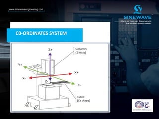
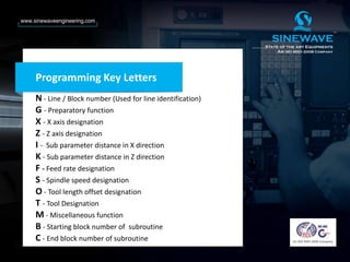
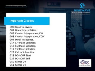
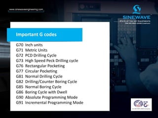
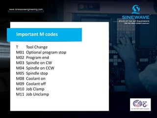
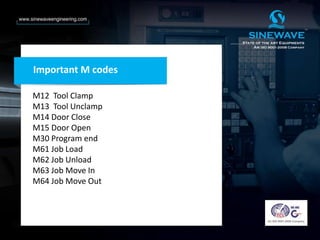
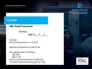
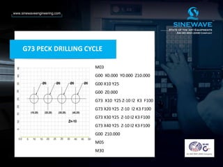
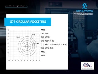
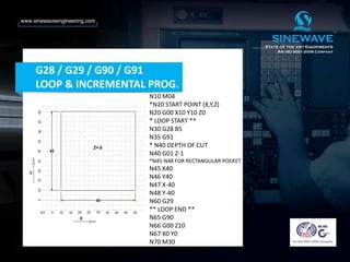
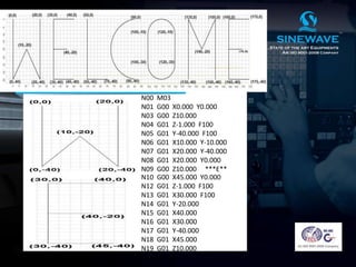
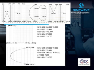
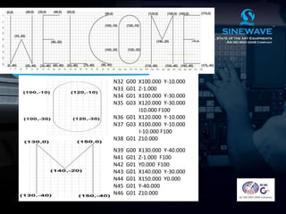
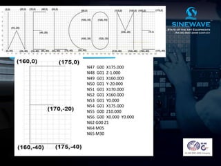
Welcomes You
TRAINING PROGRAM ON
CNC MILL TRAINER
CNC Mill Trainer
C0-ORDINATES SYSTEM
C0-ORDINATES SYSTEM
C0-ORDINATES SYSTEM
C0-ORDINATES SYSTEM
Programming Key Letters
N - Line / Block number (Used for line identification)
G - Preparatory function
X - X axis designation
Z - Z axis designation
I - Sub parameter distance in X direction
K - Sub parameter distance in Z direction
F - Feed rate designation
S - Spindle speed designation
O - Tool length offset designation
T - Tool Designation
M - Miscellaneous function
B - Starting block number of subroutine
C - End block number of subroutine
Important G codes
G00 Rapid Transverse
G01 Linear Interpolation
G02 Circular Interpolation, CW
G03 Circular Interpolation, CCW
G04 Dwell in Seconds.
G17 X-Y Plane Selection
G18 X-Z Plane Selection
G19 Y-Z Plane Selection
G22 Call to Subroutine
G28 DO-LOOP Start
G29 DO-LOOP End
G50 Mirror Off
G51 Mirror On
Important G codes
G70 Inch units
G71 Metric Units
G72 PCD Drilling Cycle
G73 High Speed Peck Drilling cycle
G76 Rectangular Pocketing
G77 Circular Pocketing
G81 Normal Drilling Cycle
G82 Drilling/Counter Boring Cycle
G85 Normal Boring Cycle
G86 Boring Cycle with Dwell
G90 Absolute Programming Mode
G91 Incremental Programming Mode
Important M codes
T Tool Change
M01 Optional program stop
M02 Program end
M03 Spindle on CW
M04 Spindle on CCW
M05 Spindle stop
M08 Coolant on
M09 Coolant off
M10 Job Clamp
M11 Job Unclamp
Important M codes
M12 Tool Clamp
M13 Tool Unclamp
M14 Door Close
M15 Door Open
M30 Program end
M61 Job Load
M62 Job Unload
M63 Job Move In
M64 Job Move Out
G codes
G00 Rapid Transverse
Format :
G00 X __ Y __ Z __
Example :
Present tool position is X = 0, Z=0.
Required tool position is X=30, Z=-30
The program code is as follows,
G00 X30
G00 Z -30
There is no machining action in G00 cycle.
It is purely rapid positioning cycle for Tool.
G codes
G01 Linear Interpolation
Format :
G01 X __ Y __ Z __F__
Here ,
F = Feed rate in mm/min.
G codes
G02 Circular Interpolation, CW
Format
G02 X__Y __ Z__ I__ J __ K__ F__
G02 X__Y __ Z__ R__ F__
Here ,
X,Y,Z = Final Co-ordinate.
I = Distance between start point & center point
of arc along X-axis.
J = Distance between start point & center point
of arc along Y-axis.
K= Distance between start point & center point
of arc along Z-axis.
R= Radius of Arc ( Used for Less Than 90 Degree )
G02 & G03 DIRECTION GUIDE :-
G03 J -VE G02 J -VE
II I
G02 I +VE G03 I -VE
G03 I +VE G02 I -VE
III IV
G02 J +VE G03 J +VE
G codes
G03 Circular Interpolation, CCW
Format :
G03 X__Y __ Z__ I__ J __ K__ F__
G03 X__Y __ Z__ R__ F_
Here ,
X,Y,Z = Final Co-ordinate.
I = Distance between start point & center point
of arc along X-axis.
J = Distance between start point & center point
of arc along Y-axis.
K= Distance between start point & center point
of arc along Z-axis.
R= Radius of Arc ( Used for Less Than 90 Degree )
For Circular Turning Aluminium Jobs Feed Rate of 30 is OK.
M03
G00 X0 Y0 Z10
G00 X7.5 Y20
G01 Z-1 F100
G03 X7.5 Y20 I12.5 J0 F100
G00 Z10
G00 X0 Y0
M05
M30
G03 EXAMPLE
G codes
G04 Dwell in Seconds.
Format : G04 I __
G04 P__
Here,
I = specifies dwell in seconds for tool movement.
P = Parameter is given then spindle will stop for
given seconds along with tool movement.
G codes
G17 X-Y Plane Selection
Format :
G17
G18 X-Z Plane Selection
Format :
G18
G19 Y-Z Plane Selection
Format :
G19
G22 SUBROUTINE CALL
Format : G22 B__ C__
Here ,
B = Start block of part program
C = End block
This code is used for calling a particular part of
program, which may repeat many times through
program.
G codes
G28 START OF DO LOOP
G28 B__
G29 END OF DO LOOP
Here ,
B = Value Indicates the no. of Repetition.
G codes
Example :
N010 ….
N020 G28 B5
N030 …..} Body OF Do Loop
N060 …..}
N090 G29
Here ,
G28 :- Do Loop Start
B :- No. Of Repetition of Do Loop
G29 :- End Of Do Loop
In this case the blocks numbered N030 to N060 will be
executed 5 times as specified by the I Word.
G codes
G codes
G50 MIRROR OFF
G51 MIRROR ON
Format
1ST Quadrant G51 I0.0 J0.0
2ND Quadrant G51 I1.0 J0.0
3RD Quadrant G51 I0.0 J1.0
4TH Quadrant G51 I1.0 J1.0
G codes
G70 Inch units
This is the modal command which commands
the controller that the dimensions specified in
blocks following the current block is in the INCH
system.
Format : G70
G71 Metric Units
METRIC format is the default format of
dimensioning.
Format : G71
G codes
G72 PCD Drilling Cycle
This cycle is used for drilling holes on a pitch
circle diameter at given angle of spacing
FORMAT :
G72 X __ Y __ Z __ R __ K __ F __
Here ,
X & Y = Center point of the PCD
Z = Drilling Depth
R = PCD Radius
K = Angle Spacing.
G codes
G73 High Speed Peck Drilling cycle
Format :
G73 X __ Y __ Z __ I __ K __ F __
Here ,
X & Y = Drill Hole Co-ordinates
Z = Total Drilling Depth
I = Peck Dwell
K = Peck Depth ( Single Cut )
G codes
G76 Rectangular Pocketing
FORMAT :
G76 X __ Y __ Z __ I __ K __ F __
Here ,
X & Y = Pocket Size
Z = Pocket Depth
I = Difference between two adjacent cuts
K = Peck (Slice ) Depth
G codes
G77 Circular Pocketing
FORMAT :
G77 X __ Y __ Z __ I __ K __ R __ F __
Here ,
X & Y = Center of Pocket
Z = Pocket Depth
I = Difference between two adjacent cuts
K = Peck (Slice ) Depth
R = Radius Of Pocket
G codes
G81 Normal Drilling Cycle
FORMAT :
G81 X __ Y __ Z __ F __
Here ,
X & Y = Drilling Position
Z = Total Depth
G codes
G82 Drilling / Counter Boring with Dwell
FORMAT :
G82 X __ Y __ Z __ I __ F __
Here ,
X & Y = Drilling Co-ordinates
Z = Pocket Depth
I = Dwell in Seconds
G codes
G85 Normal Boring Cycle
FORMAT :
G85 X __ Y __ Z __ F __
Here ,
X & Y = Boring Co-ordinates
Z = Pocket Depth
G codes
G90 Absolute Programming Mode
In this mode tool will move w.r.t. the absolute zero
point i.e. X0.000, Z0.000
Format : G90
G91 Incremental Programming Mode
In this mode tool will move the relative distance
in positive or negative direction specified by X and Z.
Format : G91
This mode is applicable for G00, G01, G02 and G03
only.
T TOOL CHANGE
Format :
T … O …..
Here ,
T = Tool Number
O = Offset table no.
M codes
M01 OPTIONAL STOP
Format :
M01
M02 PROGRAM END
Format :
M02
M codes
M03 SPINDLE ON
Format :
M03 S __
Here ,
S = Spindle Speed In RPM
( 200 – 3000 rpm )
M05 SPINDLE OFF
Format :
M05
M codes
M08 COOLENT PUMP ON
Format :
M08
M09 COOLENT PUMP OFF
Format :
M09
M codes
M10 JOB CLAMP
Format :
M10
This code closes (clamps) the chuck if available.
M11 CHUCK UNCLAMP
Format :
M11
This code opens (de-clamps) the chuck if available
M codes
M12 TOOL CLAMP
Format :
M12
This code closes (clamps) the chuck if available.
M13 TOOL UNCLAMP
Format :
M13
This code opens (de-clamps) the chuck if available
M codes
M14 DOOR CLOSE
Format :
M14
This code closes the automatic machine door if
available.
M15 DOOR OPEN
Format :
M15
This code opens the automatic machine door
if available.
M codes
M30 PROGRAM END & REWIND
Format :
M30
M codes
M61 JOB LOAD
Format :
M61
This code runs only in FMS Cycle.
M62 JOB UNLOAD
Format :
M62
This code runs only in FMS Cycle.
M codes
M63 JOB MOVE IN
Format :
M63
This code runs only in FMS Cycle.
M64 JOB MOVE OUT
Format :
M64
This code runs only in FMS Cycle.
M codes
N010 M03
N020 G51 I0.000 J0.000
N030 G22 B160 C230
N032 G50
N040 G51 I1.000 J0.000
N050 G22 B160 C230
N060 G50
N070 G51 I0.000 J1.000
N080 G22 B160 C230
N090 G50
N100 G51 I1.000 J1.000
N110 G22 B160 C230
N120 G50
G50 , G51 & G22
N130
N140 M30
N150
N160 G00 X5.000 Y5.000 Z2.000
N170 G01 Z-1 F100
N180 G01 X20.000 F100
N190 G01 Y10.000 F100
N200 G02 X10.000 Y20.000
I0.000 J10.000 F100
N210 G01 X5.000 Y20 F100
N220 G01 Y5.000 F100
N230 G00 Z10.000
G50 , G51 & G22
M03
G00 Z10
G00 X0 Y0 Z2
G72 X30 Y20 Z-10 R15 K90 F100
G00 Z10
G00 X0 Y0
M05
M30
G72 PCD DRILLING CYCLE
M03
G00 X0.000 Y0.000 Z10.000
G00 X10 Y25
G00 Z0.000
G73 X10 Y25 Z-10 I2 K3 F100
G73 X20 Y25 Z-10 I2 K3 F100
G73 X30 Y25 Z-10 I2 K3 F100
G73 X40 Y25 Z-10 I2 K3 F100
G00 Z10.000
M05
M30
G73 PECK DRILLING CYCLE
M03
G00 Z10
G00 X0 Y0
G00 X30 Y20 Z0
G77 X30 Y20 Z-3 R15 I3 K1 F100
G00 X0 Y0 Z10
M05
M30
G77 CIRCULAR POCKETING
N10 M04
*N20 START POINT (X,Y,Z)
N20 G00 X10 Y10 Z0
* LOOP START **
N30 G28 B5
N35 G91
* N40 DEPTH OF CUT
N40 G01 Z-1
*N45-N48 FOR RECTANGULAR POCKET
N45 X40
N46 Y40
N47 X-40
N48 Y-40
N60 G29
** LOOP END **
N65 G90
N66 G00 Z10
N67 X0 Y0
N70 M30
G28 / G29 / G90 / G91
LOOP & INCREMENTAL PROG.
WELCOME PROG
N00 M03
N01 G00 X0.000 Y0.000
N03 G00 Z10.000
N04 G01 Z-1.000 F100
N05 G01 Y-40.000 F100
N06 G01 X10.000 Y-10.000
N07 G01 X20.000 Y-40.000
N08 G01 X20.000 Y0.000
N09 G00 Z10.000 ***E**
N10 G00 X45.000 Y0.000
N12 G01 Z-1.000 F100
N13 G01 X30.000 F100
N14 G01 Y-20.000
N15 G01 X40.000
N16 G01 X30.000
N17 G01 Y-40.000
N18 G01 X45.000
N19 G01 Z10.000
WELCOME PROG
N20 G00 X55.000 Y0.000
N22 G01 Z-1.000
N23 G01 Y-40.000
N24 G01 X70.000
N25 G01 Z10.000
N26 G00 X90.000 Y0.000
N29 G01 Z-1.000
N30 G03 X90.000 Y-40.000
J-20.000 F100
N31 G01 Z10.000
WELCOME PROG
N32 G00 X100.000 Y-10.000
N33 G01 Z-1.000
N34 G01 X100.000 Y-30.000
N35 G03 X120.000 Y-30.000
I10.000 F100
N36 G01 X120.000 Y-10.000
N37 G03 X100.000 Y-10.000
I-10.000 F100
N38 G01 Z10.000
N39 G00 X130.000 Y-40.000
N41 G01 Z-1.000 F100
N42 G01 Y0.000 F100
N43 G01 X140.000 Y-30.000
N44 G01 X150.000 Y0.000
N45 G01 Y-40.000
N46 G01 Z10.000
WELCOME PROG
N47 G00 X175.000
N48 G01 Z-1.000
N49 G01 X160.000
N50 G01 Y-20.000
N51 G01 X170.000
N52 G01 X160.000
N53 G01 Y0.000
N54 G01 X175.000
N55 G00 Z10.000
N56 G00 X0.000 Y0.000
N62 G00 Z1
N64 M05
N65 M30
MILL - TRAINING.pptx

MILL - TRAINING.pptx

  • 1.
    Welcomes You TRAINING PROGRAMON CNC MILL TRAINER
  • 2.
  • 3.
  • 4.
  • 5.
  • 6.
  • 7.
    Programming Key Letters N- Line / Block number (Used for line identification) G - Preparatory function X - X axis designation Z - Z axis designation I - Sub parameter distance in X direction K - Sub parameter distance in Z direction F - Feed rate designation S - Spindle speed designation O - Tool length offset designation T - Tool Designation M - Miscellaneous function B - Starting block number of subroutine C - End block number of subroutine
  • 8.
    Important G codes G00Rapid Transverse G01 Linear Interpolation G02 Circular Interpolation, CW G03 Circular Interpolation, CCW G04 Dwell in Seconds. G17 X-Y Plane Selection G18 X-Z Plane Selection G19 Y-Z Plane Selection G22 Call to Subroutine G28 DO-LOOP Start G29 DO-LOOP End G50 Mirror Off G51 Mirror On
  • 9.
    Important G codes G70Inch units G71 Metric Units G72 PCD Drilling Cycle G73 High Speed Peck Drilling cycle G76 Rectangular Pocketing G77 Circular Pocketing G81 Normal Drilling Cycle G82 Drilling/Counter Boring Cycle G85 Normal Boring Cycle G86 Boring Cycle with Dwell G90 Absolute Programming Mode G91 Incremental Programming Mode
  • 10.
    Important M codes TTool Change M01 Optional program stop M02 Program end M03 Spindle on CW M04 Spindle on CCW M05 Spindle stop M08 Coolant on M09 Coolant off M10 Job Clamp M11 Job Unclamp
  • 11.
    Important M codes M12Tool Clamp M13 Tool Unclamp M14 Door Close M15 Door Open M30 Program end M61 Job Load M62 Job Unload M63 Job Move In M64 Job Move Out
  • 12.
    G codes G00 RapidTransverse Format : G00 X __ Y __ Z __ Example : Present tool position is X = 0, Z=0. Required tool position is X=30, Z=-30 The program code is as follows, G00 X30 G00 Z -30 There is no machining action in G00 cycle. It is purely rapid positioning cycle for Tool.
  • 13.
    G codes G01 LinearInterpolation Format : G01 X __ Y __ Z __F__ Here , F = Feed rate in mm/min.
  • 14.
    G codes G02 CircularInterpolation, CW Format G02 X__Y __ Z__ I__ J __ K__ F__ G02 X__Y __ Z__ R__ F__ Here , X,Y,Z = Final Co-ordinate. I = Distance between start point & center point of arc along X-axis. J = Distance between start point & center point of arc along Y-axis. K= Distance between start point & center point of arc along Z-axis. R= Radius of Arc ( Used for Less Than 90 Degree )
  • 15.
    G02 & G03DIRECTION GUIDE :- G03 J -VE G02 J -VE II I G02 I +VE G03 I -VE G03 I +VE G02 I -VE III IV G02 J +VE G03 J +VE
  • 16.
    G codes G03 CircularInterpolation, CCW Format : G03 X__Y __ Z__ I__ J __ K__ F__ G03 X__Y __ Z__ R__ F_ Here , X,Y,Z = Final Co-ordinate. I = Distance between start point & center point of arc along X-axis. J = Distance between start point & center point of arc along Y-axis. K= Distance between start point & center point of arc along Z-axis. R= Radius of Arc ( Used for Less Than 90 Degree )
  • 17.
    For Circular TurningAluminium Jobs Feed Rate of 30 is OK. For Circular Turning Aluminium Jobs Feed Rate of 30 is OK. For Circular Turning Aluminium Jobs Feed Rate of 30 is OK. For Circular Turning Aluminium Jobs Feed Rate of 30 is OK. For Circular Turning Aluminium Jobs Feed Rate of 30 is OK. M03 G00 X0 Y0 Z10 G00 X7.5 Y20 G01 Z-1 F100 G03 X7.5 Y20 I12.5 J0 F100 G00 Z10 G00 X0 Y0 M05 M30 G03 EXAMPLE
  • 18.
    G codes G04 Dwellin Seconds. Format : G04 I __ G04 P__ Here, I = specifies dwell in seconds for tool movement. P = Parameter is given then spindle will stop for given seconds along with tool movement.
  • 19.
    G codes G17 X-YPlane Selection Format : G17 G18 X-Z Plane Selection Format : G18 G19 Y-Z Plane Selection Format : G19
  • 20.
    G22 SUBROUTINE CALL Format: G22 B__ C__ Here , B = Start block of part program C = End block This code is used for calling a particular part of program, which may repeat many times through program. G codes
  • 21.
    G28 START OFDO LOOP G28 B__ G29 END OF DO LOOP Here , B = Value Indicates the no. of Repetition. G codes
  • 22.
    Example : N010 …. N020G28 B5 N030 …..} Body OF Do Loop N060 …..} N090 G29 Here , G28 :- Do Loop Start B :- No. Of Repetition of Do Loop G29 :- End Of Do Loop In this case the blocks numbered N030 to N060 will be executed 5 times as specified by the I Word. G codes
  • 23.
    G codes G50 MIRROROFF G51 MIRROR ON Format 1ST Quadrant G51 I0.0 J0.0 2ND Quadrant G51 I1.0 J0.0 3RD Quadrant G51 I0.0 J1.0 4TH Quadrant G51 I1.0 J1.0
  • 24.
    G codes G70 Inchunits This is the modal command which commands the controller that the dimensions specified in blocks following the current block is in the INCH system. Format : G70 G71 Metric Units METRIC format is the default format of dimensioning. Format : G71
  • 25.
    G codes G72 PCDDrilling Cycle This cycle is used for drilling holes on a pitch circle diameter at given angle of spacing FORMAT : G72 X __ Y __ Z __ R __ K __ F __ Here , X & Y = Center point of the PCD Z = Drilling Depth R = PCD Radius K = Angle Spacing.
  • 26.
    G codes G73 HighSpeed Peck Drilling cycle Format : G73 X __ Y __ Z __ I __ K __ F __ Here , X & Y = Drill Hole Co-ordinates Z = Total Drilling Depth I = Peck Dwell K = Peck Depth ( Single Cut )
  • 27.
    G codes G76 RectangularPocketing FORMAT : G76 X __ Y __ Z __ I __ K __ F __ Here , X & Y = Pocket Size Z = Pocket Depth I = Difference between two adjacent cuts K = Peck (Slice ) Depth
  • 28.
    G codes G77 CircularPocketing FORMAT : G77 X __ Y __ Z __ I __ K __ R __ F __ Here , X & Y = Center of Pocket Z = Pocket Depth I = Difference between two adjacent cuts K = Peck (Slice ) Depth R = Radius Of Pocket
  • 29.
    G codes G81 NormalDrilling Cycle FORMAT : G81 X __ Y __ Z __ F __ Here , X & Y = Drilling Position Z = Total Depth
  • 30.
    G codes G82 Drilling/ Counter Boring with Dwell FORMAT : G82 X __ Y __ Z __ I __ F __ Here , X & Y = Drilling Co-ordinates Z = Pocket Depth I = Dwell in Seconds
  • 31.
    G codes G85 NormalBoring Cycle FORMAT : G85 X __ Y __ Z __ F __ Here , X & Y = Boring Co-ordinates Z = Pocket Depth
  • 32.
    G codes G90 AbsoluteProgramming Mode In this mode tool will move w.r.t. the absolute zero point i.e. X0.000, Z0.000 Format : G90 G91 Incremental Programming Mode In this mode tool will move the relative distance in positive or negative direction specified by X and Z. Format : G91 This mode is applicable for G00, G01, G02 and G03 only.
  • 33.
    T TOOL CHANGE Format: T … O ….. Here , T = Tool Number O = Offset table no. M codes
  • 34.
    M01 OPTIONAL STOP Format: M01 M02 PROGRAM END Format : M02 M codes
  • 35.
    M03 SPINDLE ON Format: M03 S __ Here , S = Spindle Speed In RPM ( 200 – 3000 rpm ) M05 SPINDLE OFF Format : M05 M codes
  • 36.
    M08 COOLENT PUMPON Format : M08 M09 COOLENT PUMP OFF Format : M09 M codes
  • 37.
    M10 JOB CLAMP Format: M10 This code closes (clamps) the chuck if available. M11 CHUCK UNCLAMP Format : M11 This code opens (de-clamps) the chuck if available M codes
  • 38.
    M12 TOOL CLAMP Format: M12 This code closes (clamps) the chuck if available. M13 TOOL UNCLAMP Format : M13 This code opens (de-clamps) the chuck if available M codes
  • 39.
    M14 DOOR CLOSE Format: M14 This code closes the automatic machine door if available. M15 DOOR OPEN Format : M15 This code opens the automatic machine door if available. M codes
  • 40.
    M30 PROGRAM END& REWIND Format : M30 M codes
  • 41.
    M61 JOB LOAD Format: M61 This code runs only in FMS Cycle. M62 JOB UNLOAD Format : M62 This code runs only in FMS Cycle. M codes
  • 42.
    M63 JOB MOVEIN Format : M63 This code runs only in FMS Cycle. M64 JOB MOVE OUT Format : M64 This code runs only in FMS Cycle. M codes
  • 43.
    N010 M03 N020 G51I0.000 J0.000 N030 G22 B160 C230 N032 G50 N040 G51 I1.000 J0.000 N050 G22 B160 C230 N060 G50 N070 G51 I0.000 J1.000 N080 G22 B160 C230 N090 G50 N100 G51 I1.000 J1.000 N110 G22 B160 C230 N120 G50 G50 , G51 & G22
  • 44.
    N130 N140 M30 N150 N160 G00X5.000 Y5.000 Z2.000 N170 G01 Z-1 F100 N180 G01 X20.000 F100 N190 G01 Y10.000 F100 N200 G02 X10.000 Y20.000 I0.000 J10.000 F100 N210 G01 X5.000 Y20 F100 N220 G01 Y5.000 F100 N230 G00 Z10.000 G50 , G51 & G22
  • 45.
    M03 G00 Z10 G00 X0Y0 Z2 G72 X30 Y20 Z-10 R15 K90 F100 G00 Z10 G00 X0 Y0 M05 M30 G72 PCD DRILLING CYCLE
  • 46.
    M03 G00 X0.000 Y0.000Z10.000 G00 X10 Y25 G00 Z0.000 G73 X10 Y25 Z-10 I2 K3 F100 G73 X20 Y25 Z-10 I2 K3 F100 G73 X30 Y25 Z-10 I2 K3 F100 G73 X40 Y25 Z-10 I2 K3 F100 G00 Z10.000 M05 M30 G73 PECK DRILLING CYCLE
  • 47.
    M03 G00 Z10 G00 X0Y0 G00 X30 Y20 Z0 G77 X30 Y20 Z-3 R15 I3 K1 F100 G00 X0 Y0 Z10 M05 M30 G77 CIRCULAR POCKETING
  • 48.
    N10 M04 *N20 STARTPOINT (X,Y,Z) N20 G00 X10 Y10 Z0 * LOOP START ** N30 G28 B5 N35 G91 * N40 DEPTH OF CUT N40 G01 Z-1 *N45-N48 FOR RECTANGULAR POCKET N45 X40 N46 Y40 N47 X-40 N48 Y-40 N60 G29 ** LOOP END ** N65 G90 N66 G00 Z10 N67 X0 Y0 N70 M30 G28 / G29 / G90 / G91 LOOP & INCREMENTAL PROG.
  • 49.
    WELCOME PROG N00 M03 N01G00 X0.000 Y0.000 N03 G00 Z10.000 N04 G01 Z-1.000 F100 N05 G01 Y-40.000 F100 N06 G01 X10.000 Y-10.000 N07 G01 X20.000 Y-40.000 N08 G01 X20.000 Y0.000 N09 G00 Z10.000 ***E** N10 G00 X45.000 Y0.000 N12 G01 Z-1.000 F100 N13 G01 X30.000 F100 N14 G01 Y-20.000 N15 G01 X40.000 N16 G01 X30.000 N17 G01 Y-40.000 N18 G01 X45.000 N19 G01 Z10.000
  • 50.
    WELCOME PROG N20 G00X55.000 Y0.000 N22 G01 Z-1.000 N23 G01 Y-40.000 N24 G01 X70.000 N25 G01 Z10.000 N26 G00 X90.000 Y0.000 N29 G01 Z-1.000 N30 G03 X90.000 Y-40.000 J-20.000 F100 N31 G01 Z10.000
  • 51.
    WELCOME PROG N32 G00X100.000 Y-10.000 N33 G01 Z-1.000 N34 G01 X100.000 Y-30.000 N35 G03 X120.000 Y-30.000 I10.000 F100 N36 G01 X120.000 Y-10.000 N37 G03 X100.000 Y-10.000 I-10.000 F100 N38 G01 Z10.000 N39 G00 X130.000 Y-40.000 N41 G01 Z-1.000 F100 N42 G01 Y0.000 F100 N43 G01 X140.000 Y-30.000 N44 G01 X150.000 Y0.000 N45 G01 Y-40.000 N46 G01 Z10.000
  • 52.
    WELCOME PROG N47 G00X175.000 N48 G01 Z-1.000 N49 G01 X160.000 N50 G01 Y-20.000 N51 G01 X170.000 N52 G01 X160.000 N53 G01 Y0.000 N54 G01 X175.000 N55 G00 Z10.000 N56 G00 X0.000 Y0.000 N62 G00 Z1 N64 M05 N65 M30