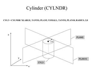
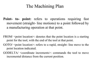
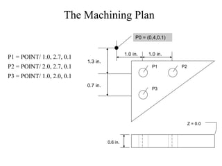
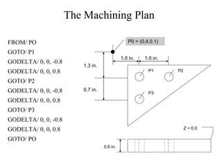
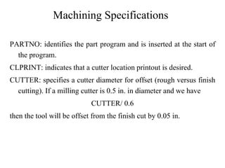
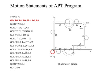
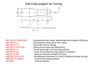
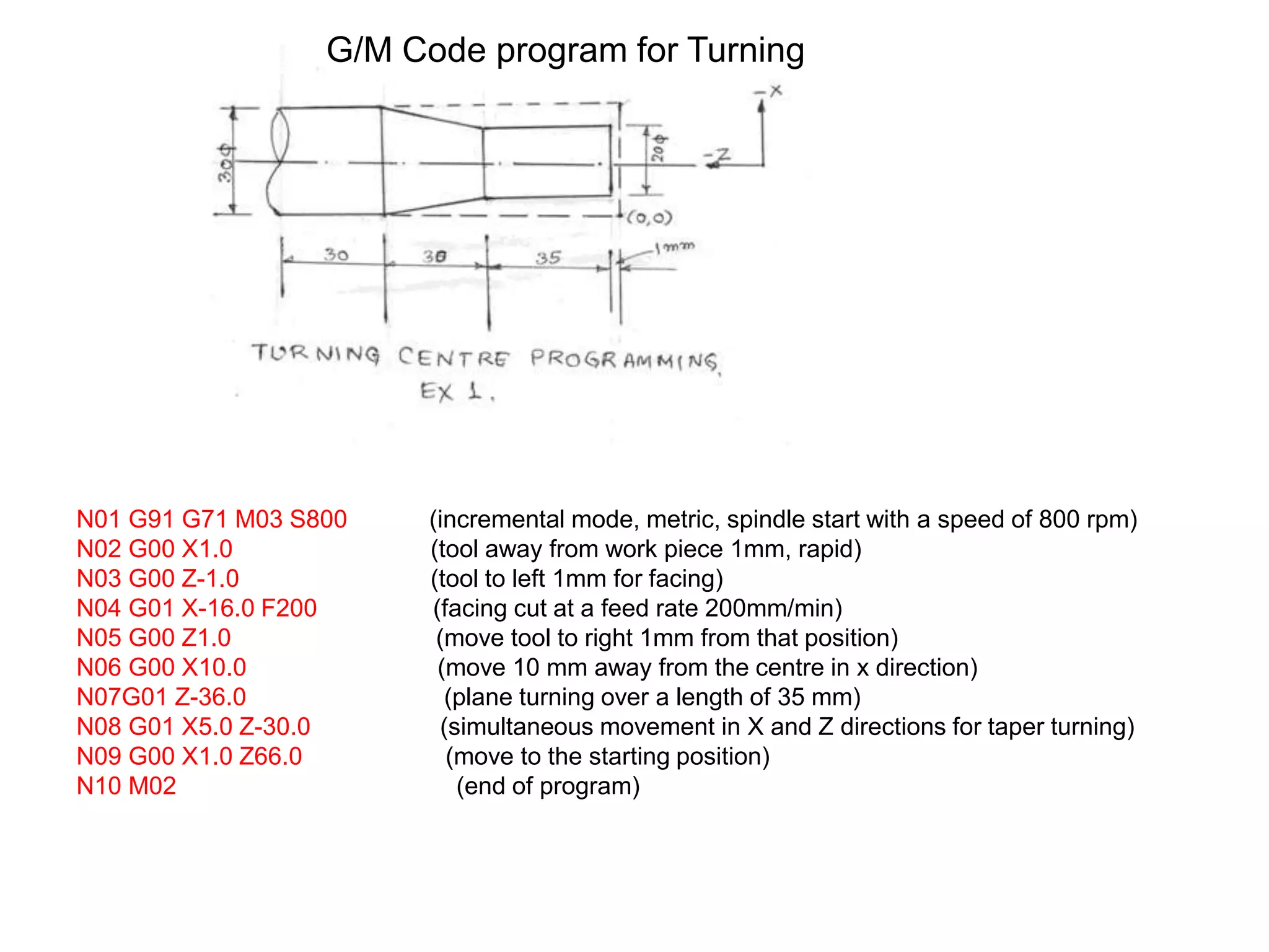
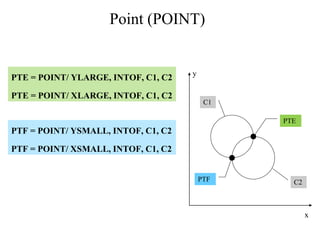
The document describes a G-code program for turning operations. The program contains 10 lines of code that perform various tool motions including rapid positioning, facing, plane turning, and taper turning operations. The final line ends the program.
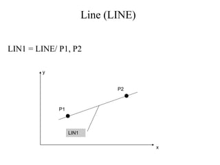
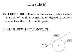
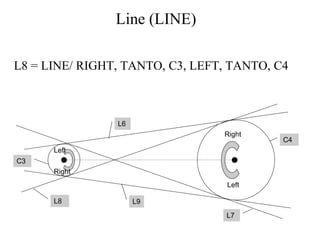
![Line (LINE)
LIN = LINE/ SLOPE, SLOPE VALUE, INTERC, MODIFIER, d
where the slope value is y/x. The modifier options are [XAXIS,
YAXIS], and d is the corresponding intercept value on the selected
axis (i.e., modifier).
x
y
(6,0) Point of X-Intercept
LINE1
LINE1 = LINE/ SLOPE, 1, INTERC, XAXIS, 6](https://image.slidesharecdn.com/unit-3aptpartprogramming-211119050039/85/APT-part-programming-20-320.jpg)
![Line (LINE)
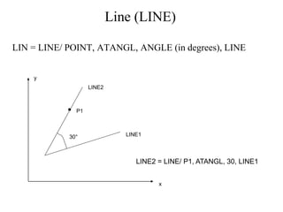
LIN = LINE/ ATANGL, DEGREES, INTERC, MODIFIER, d
The modifier options are [XAXIS, YAXIS], and d is the
corresponding intercept value on the selected axis (i.e., modifier).
x
y
d
LINE1
= 30°
LINE1 = LINE/ ATANGL, 30, INTERC, XAXIS ,d](https://image.slidesharecdn.com/unit-3aptpartprogramming-211119050039/85/APT-part-programming-21-320.jpg)