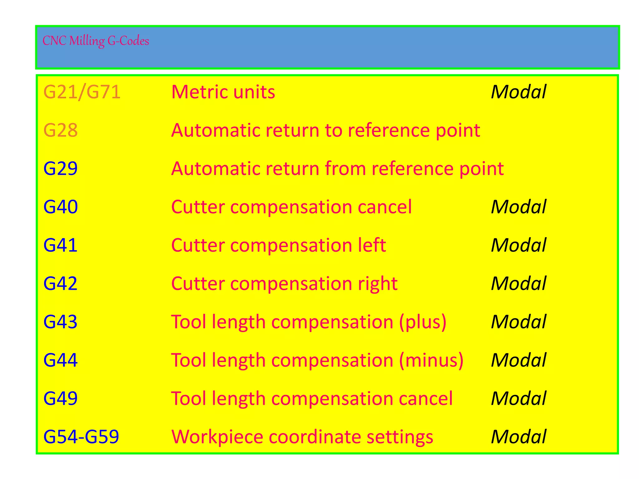
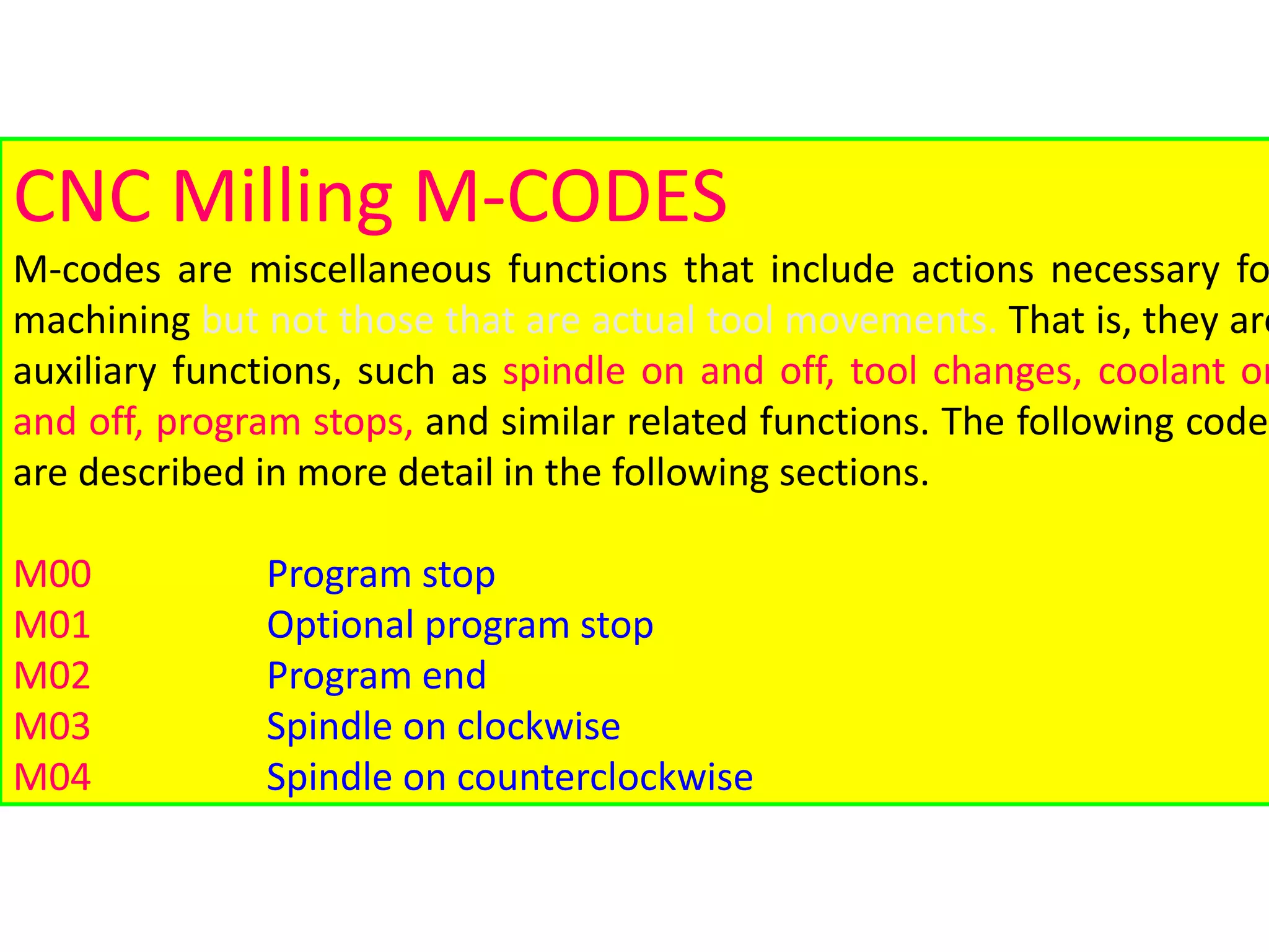
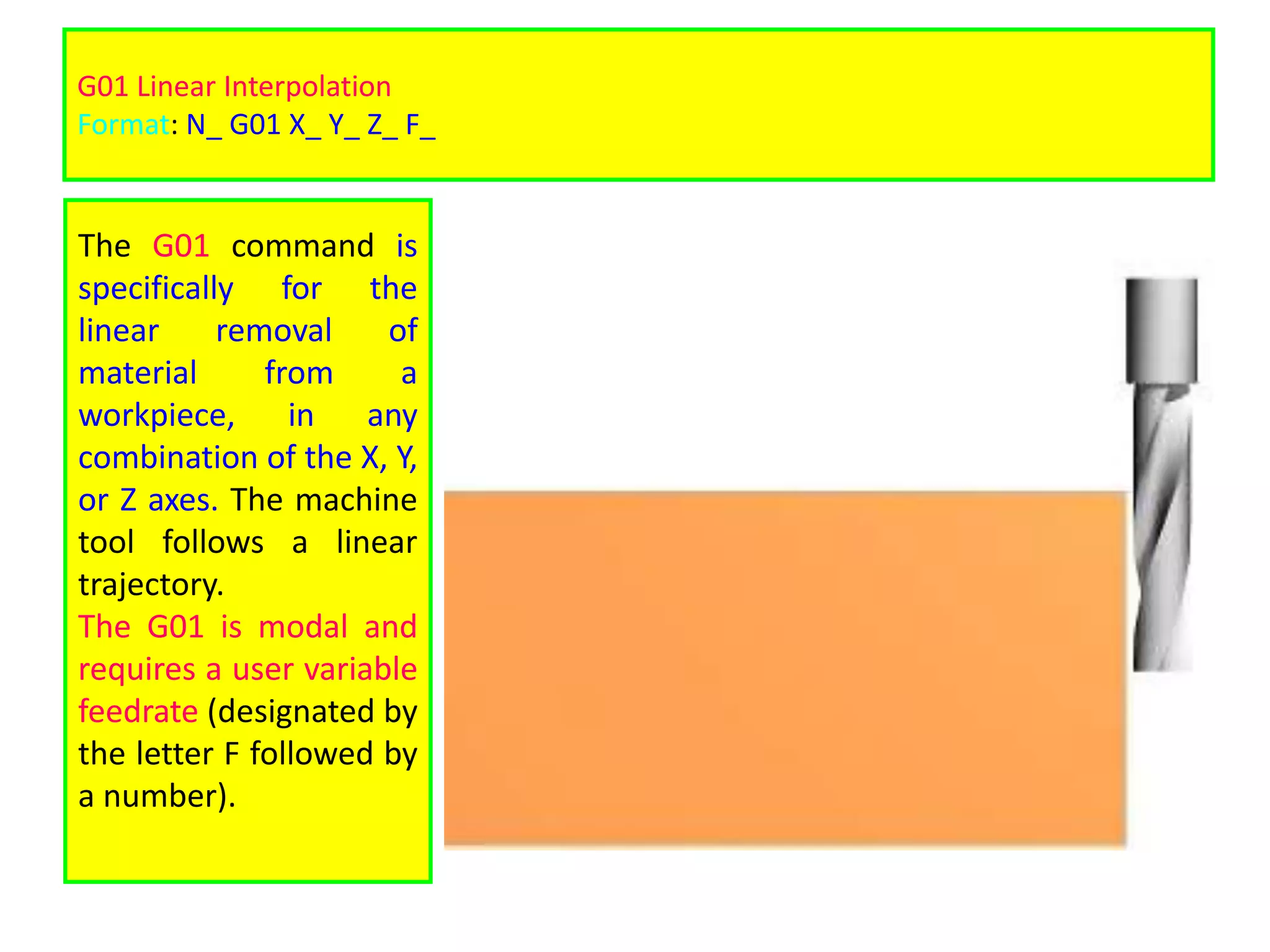
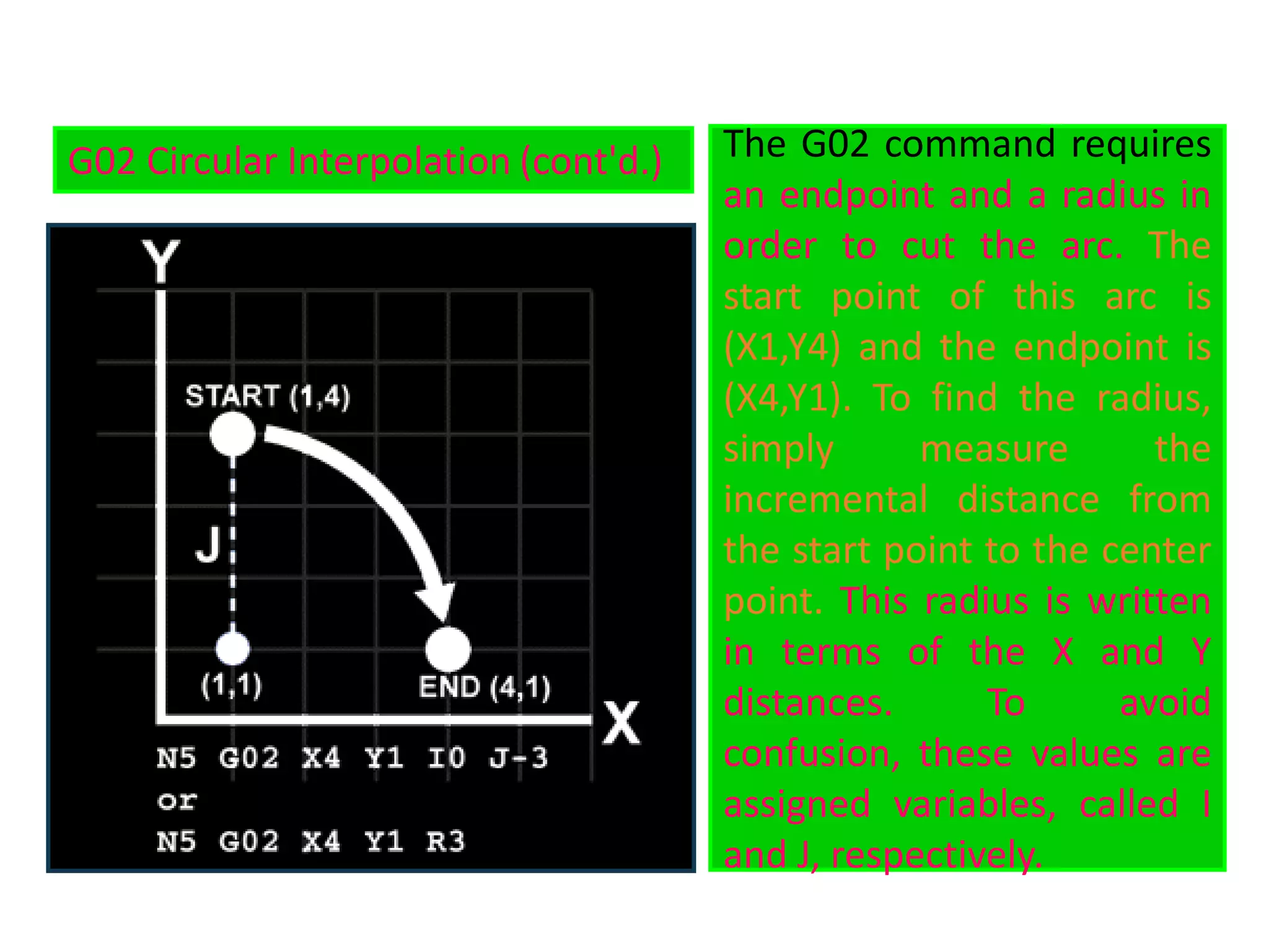
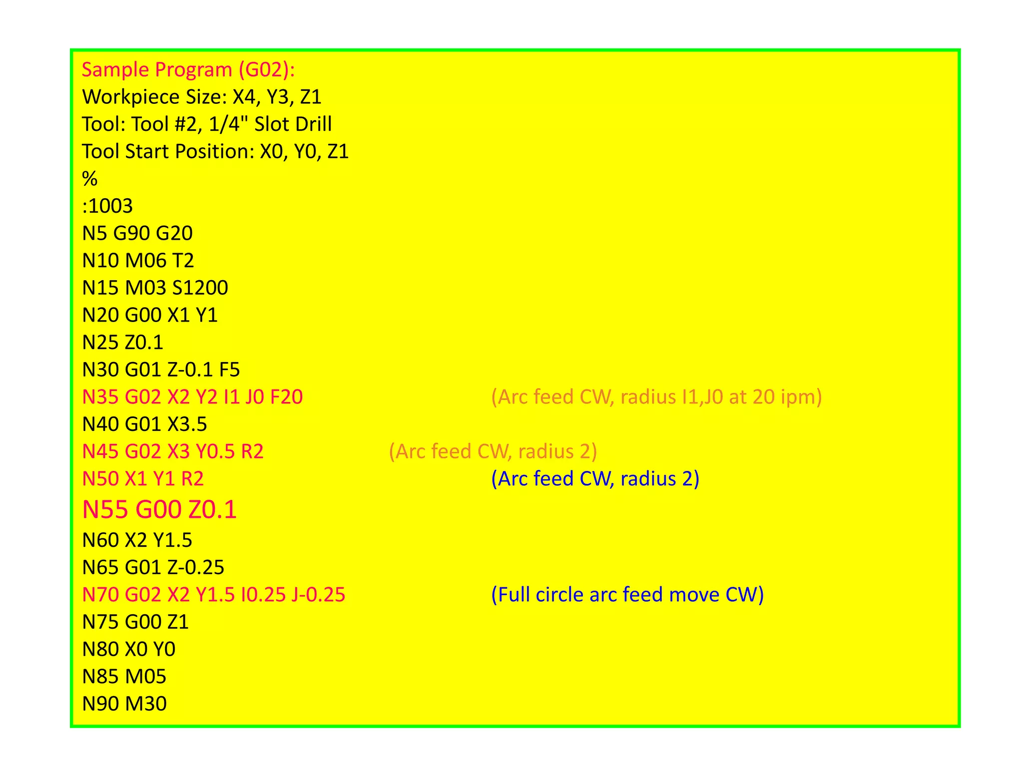
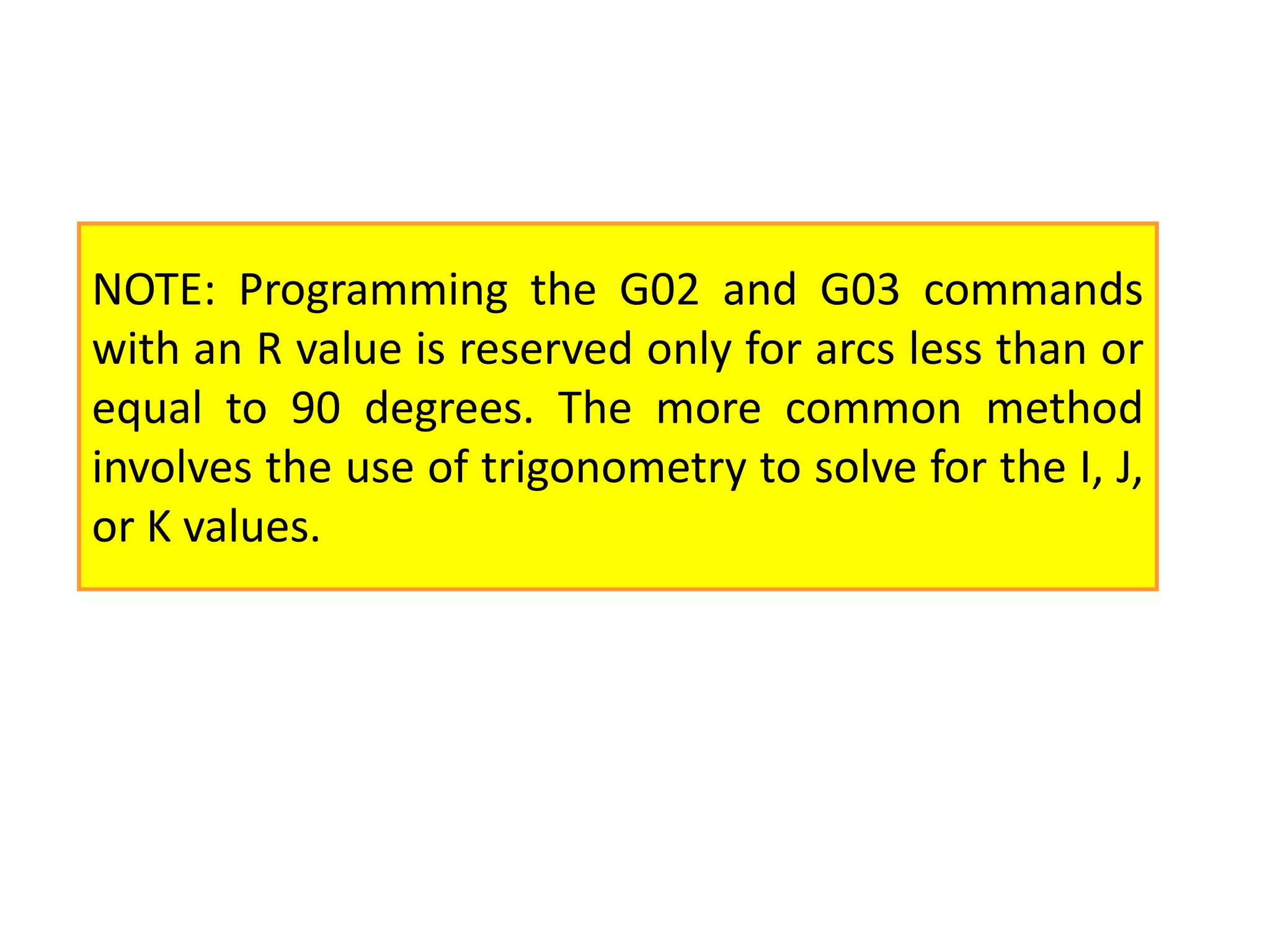
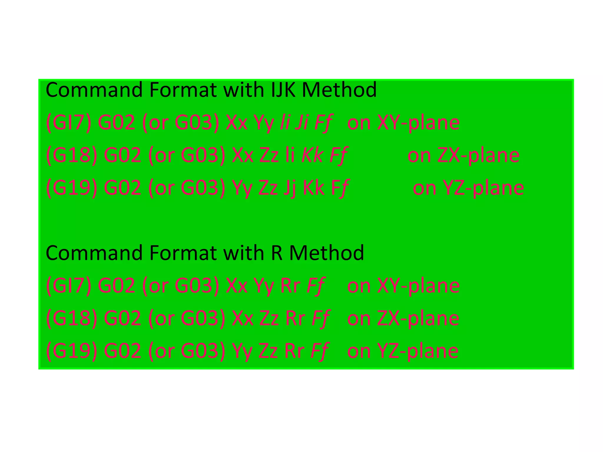
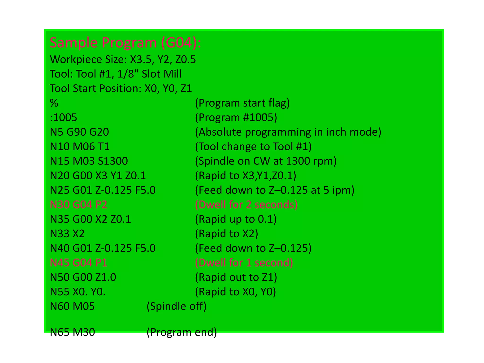
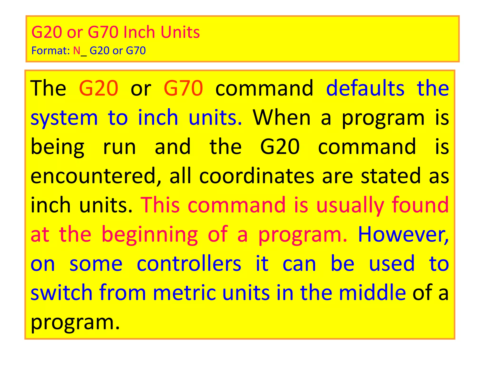
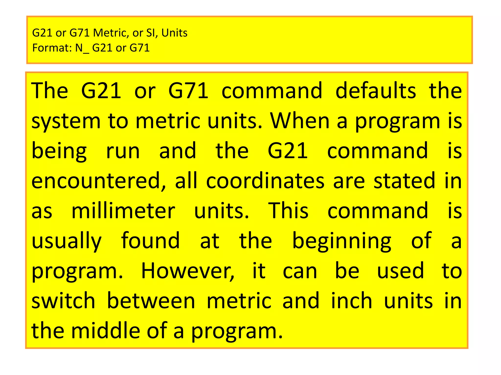
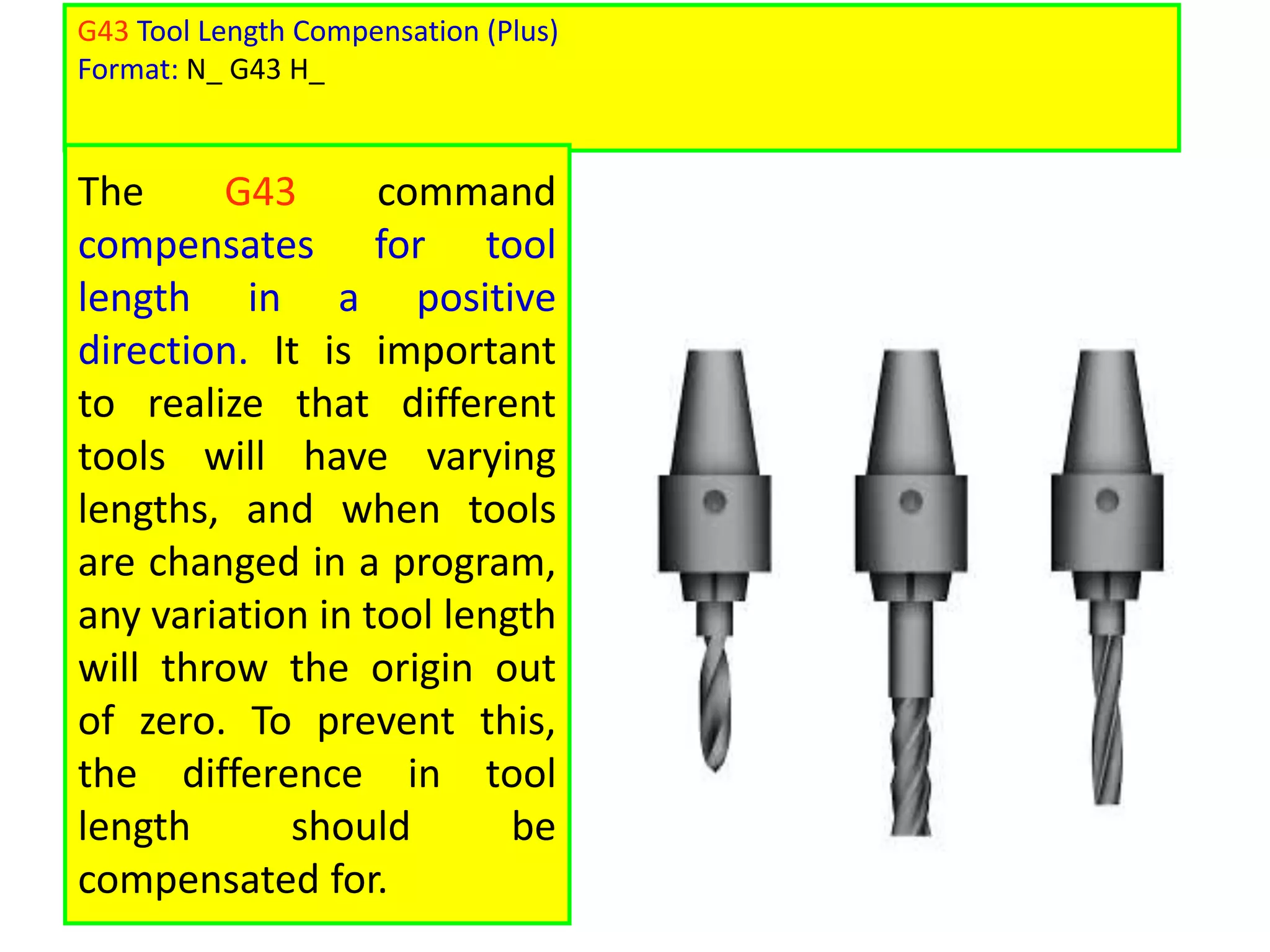
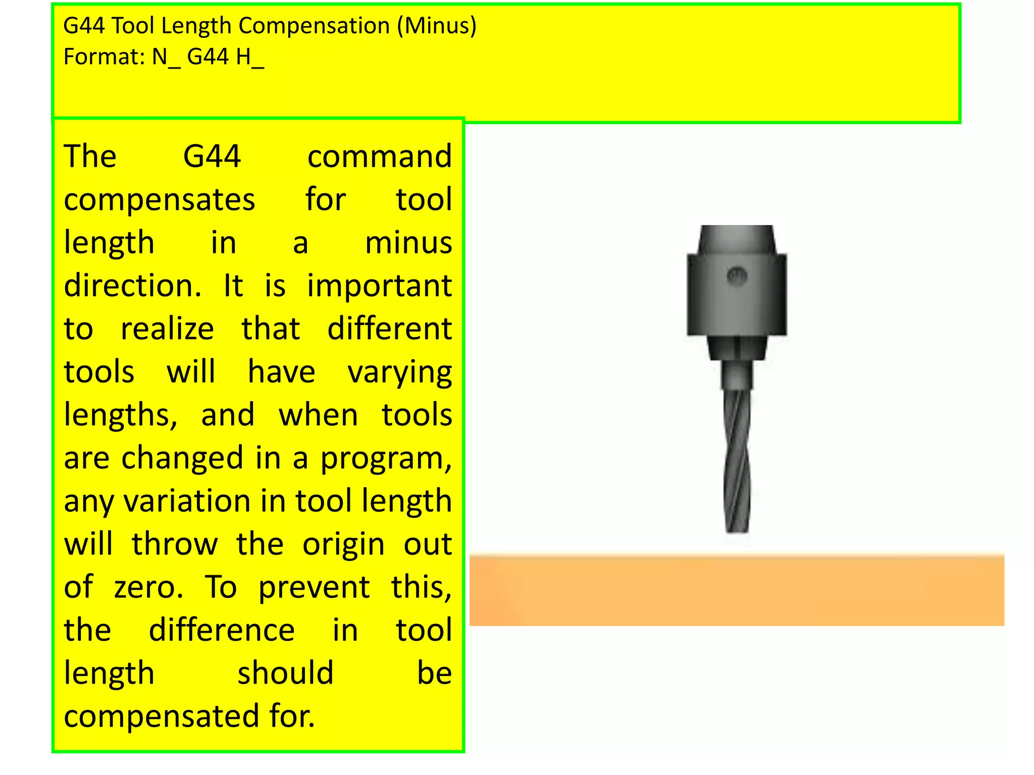
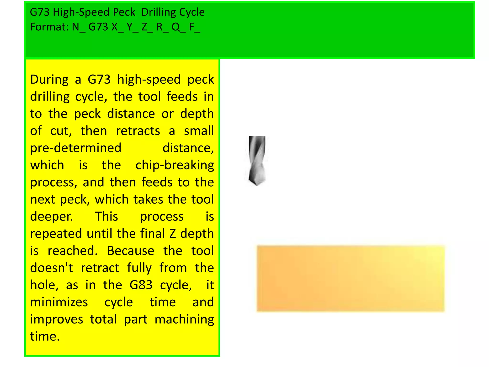
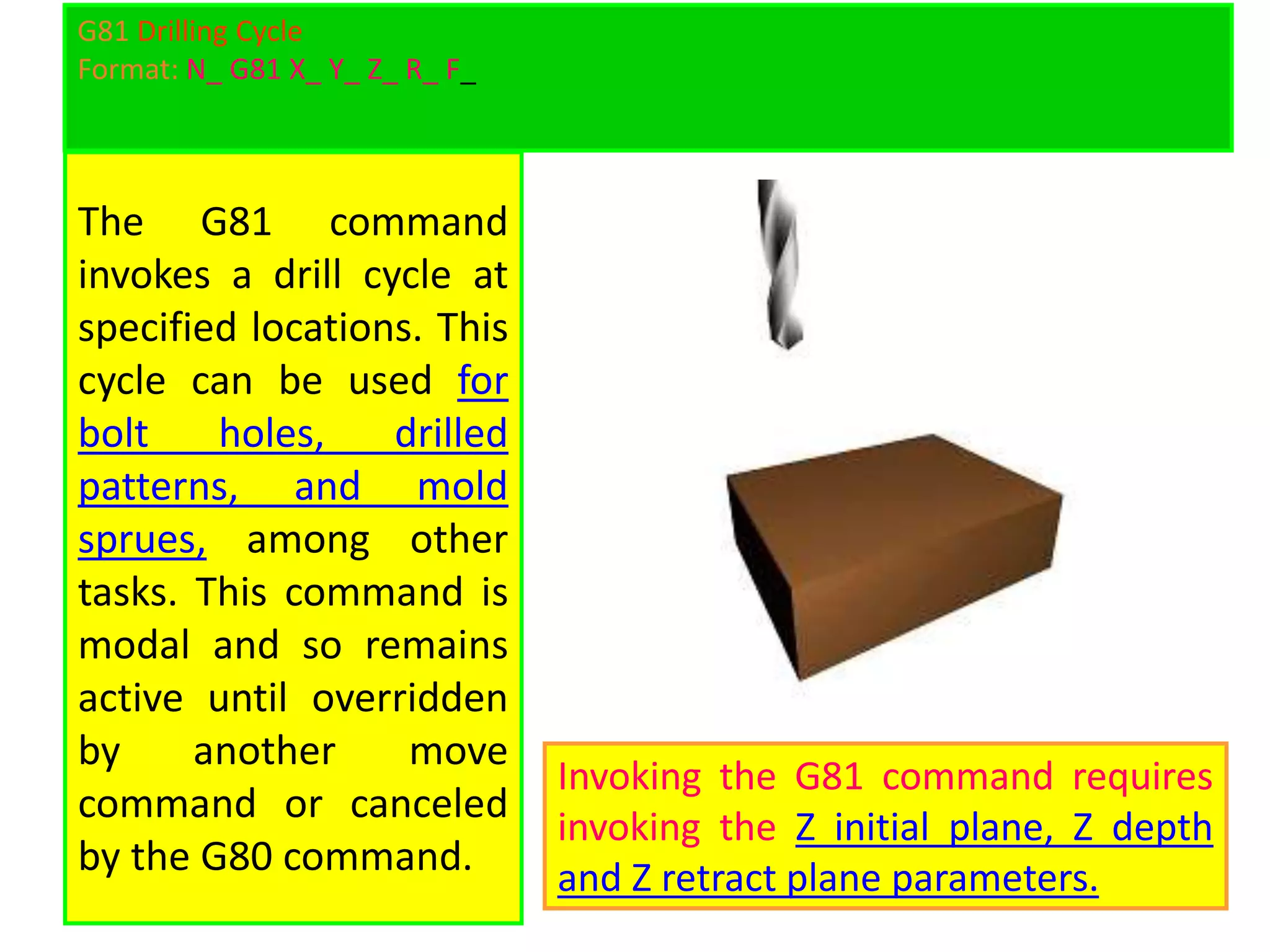
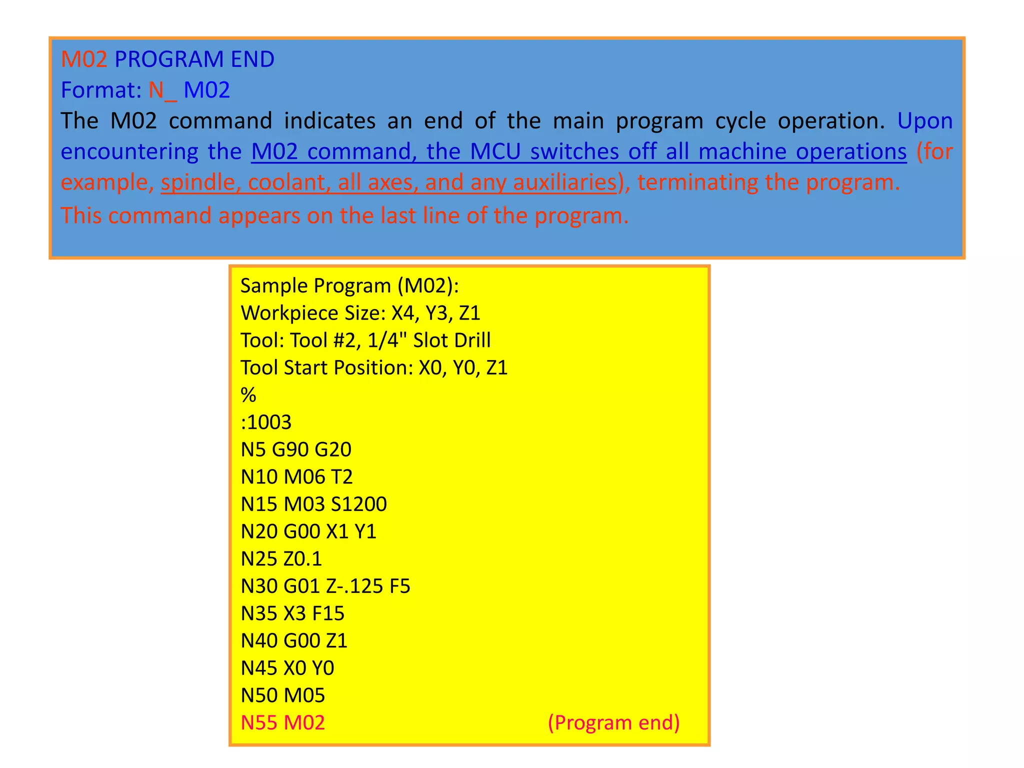
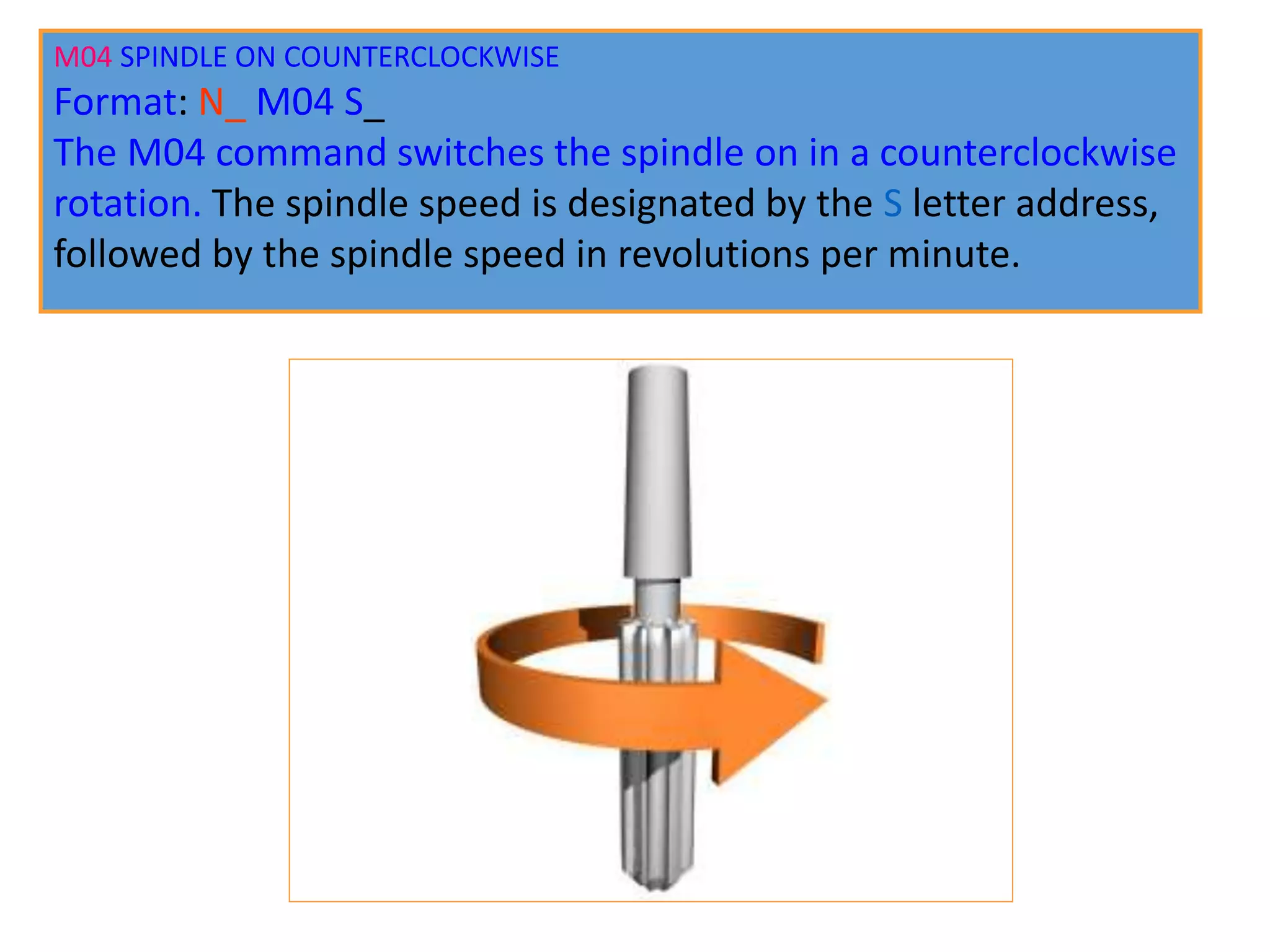
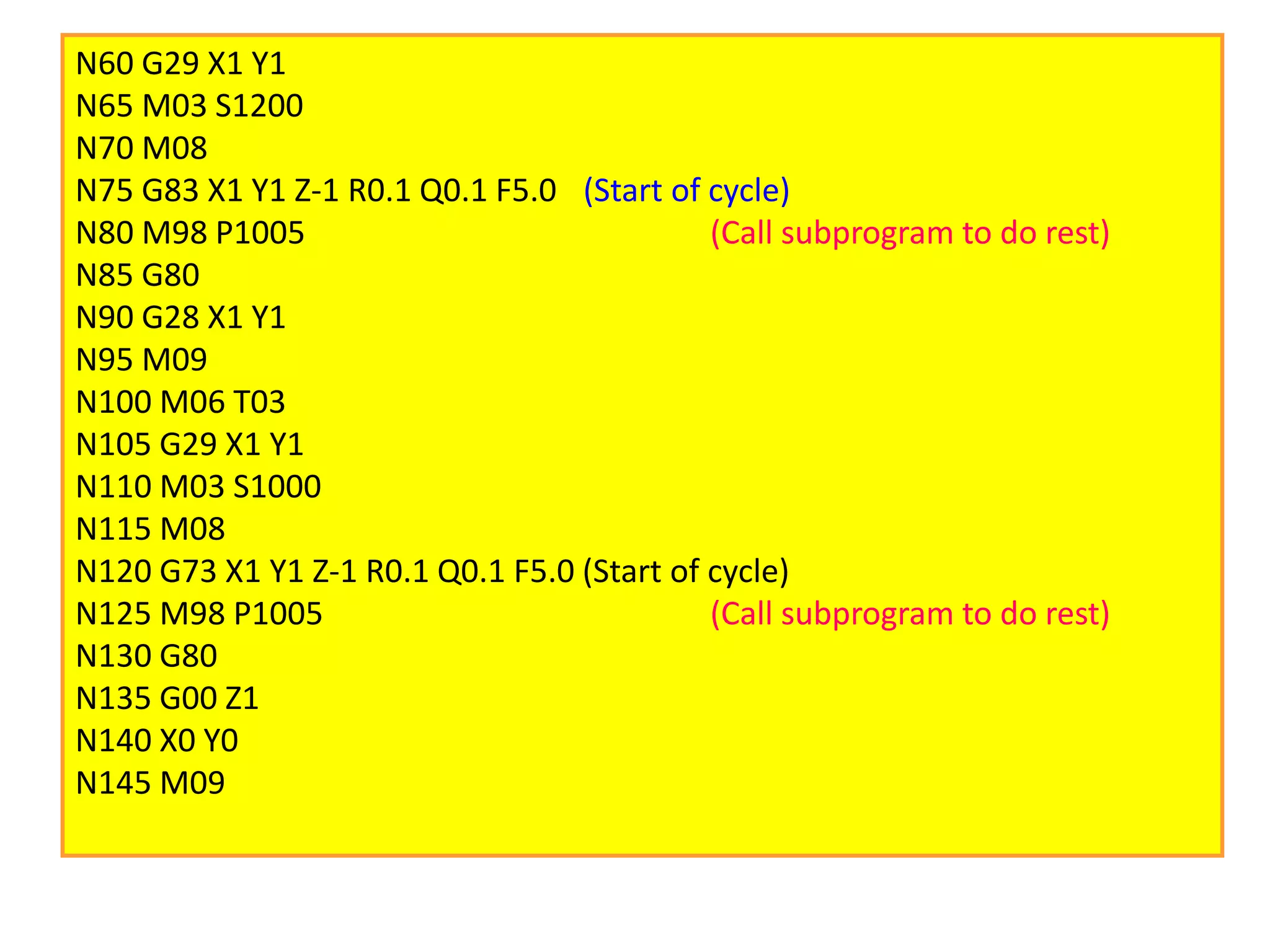
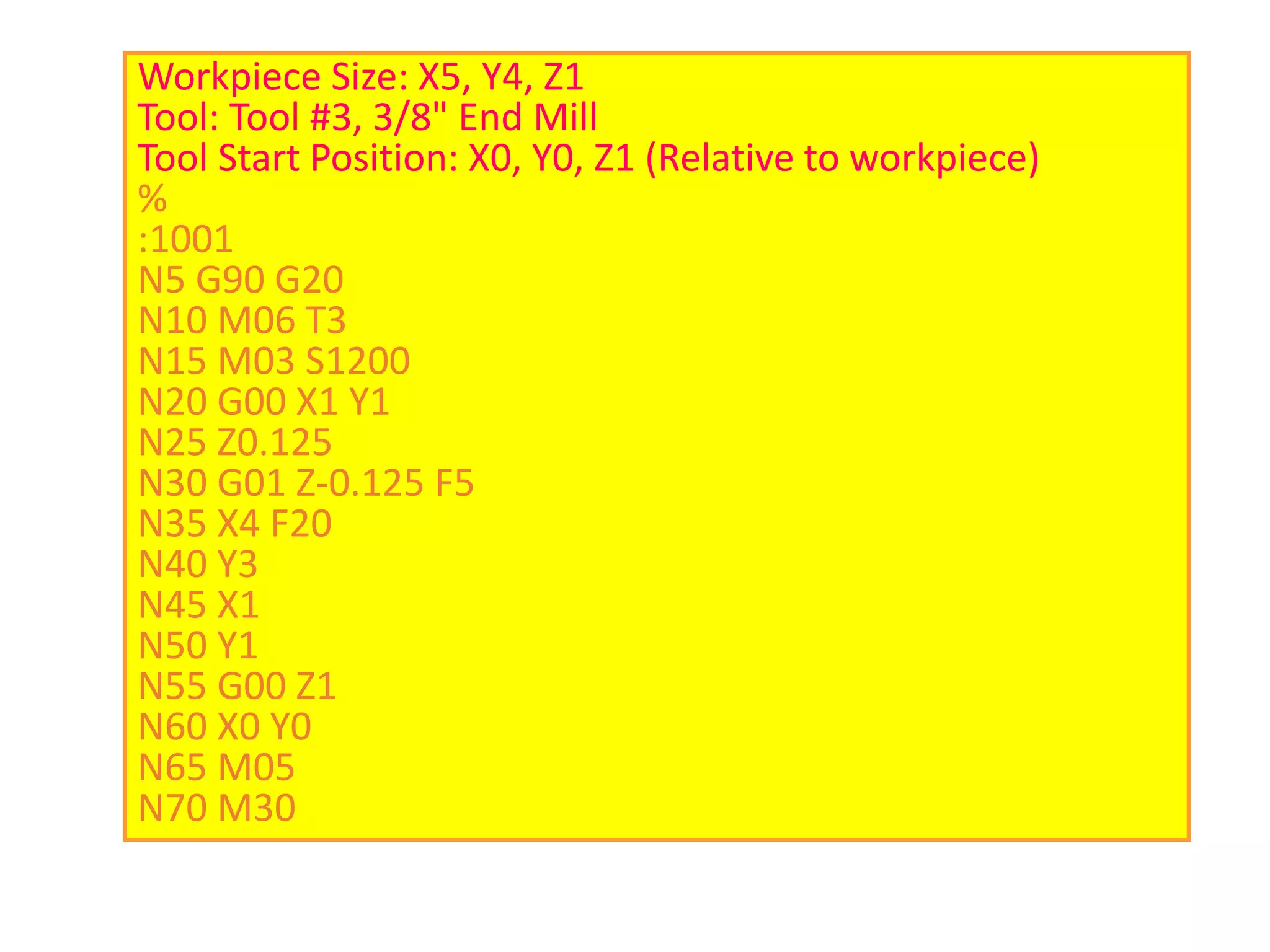
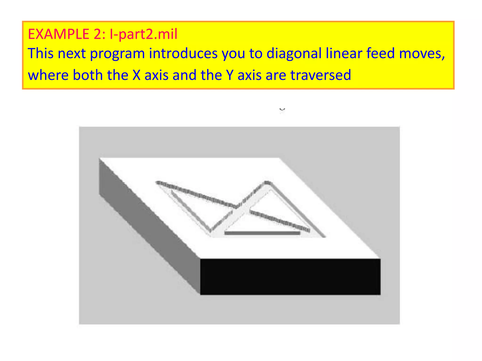
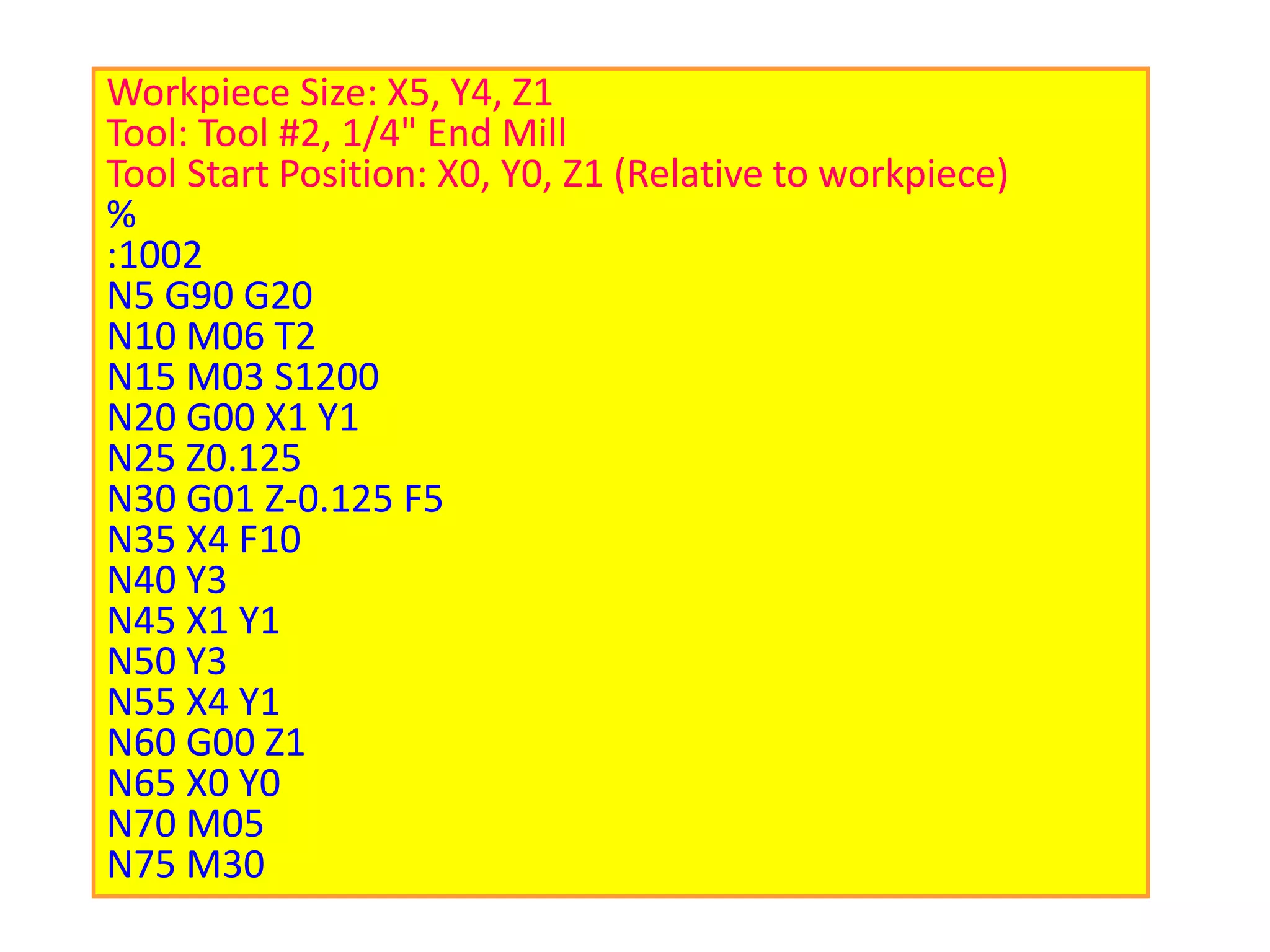
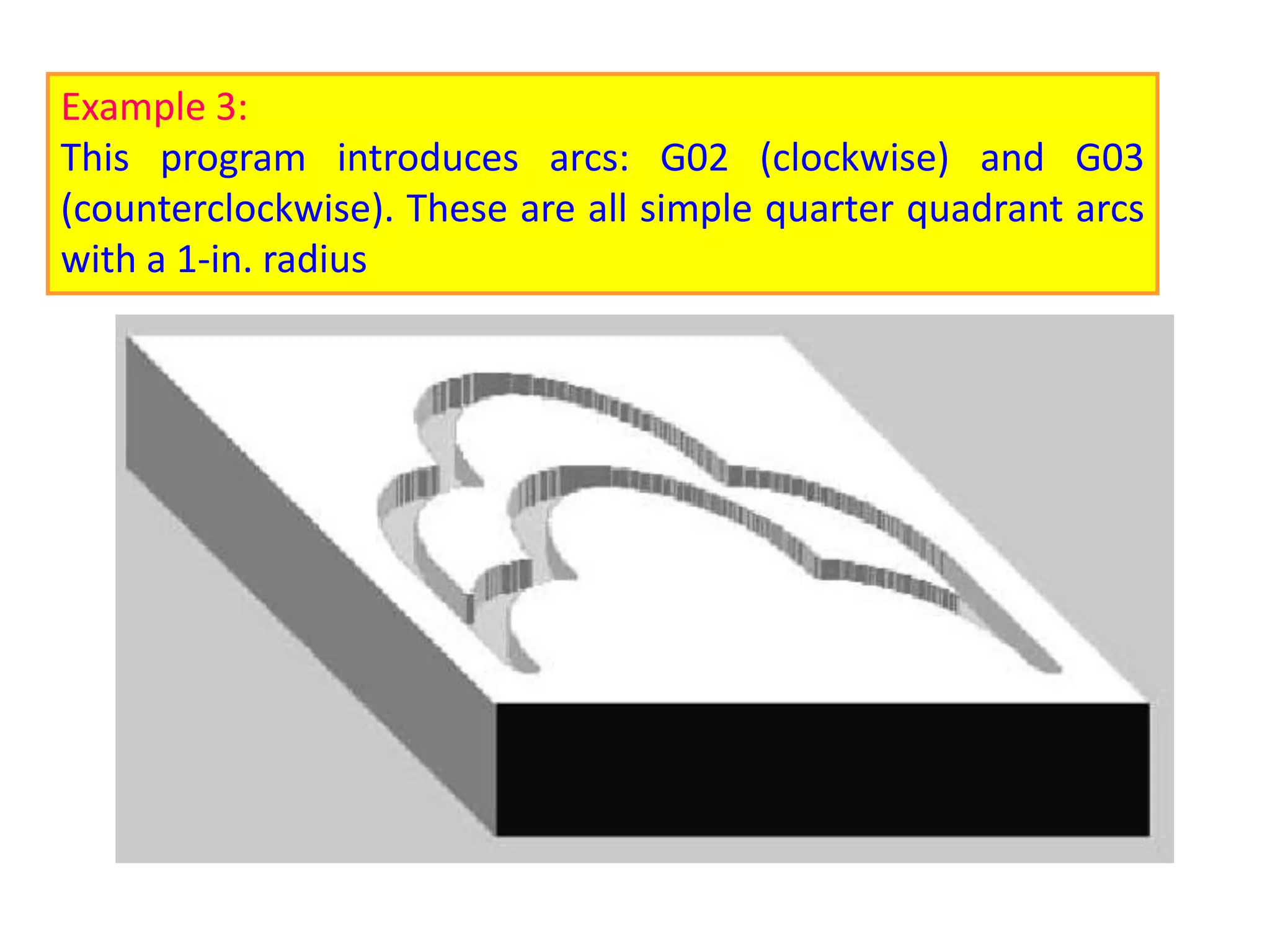
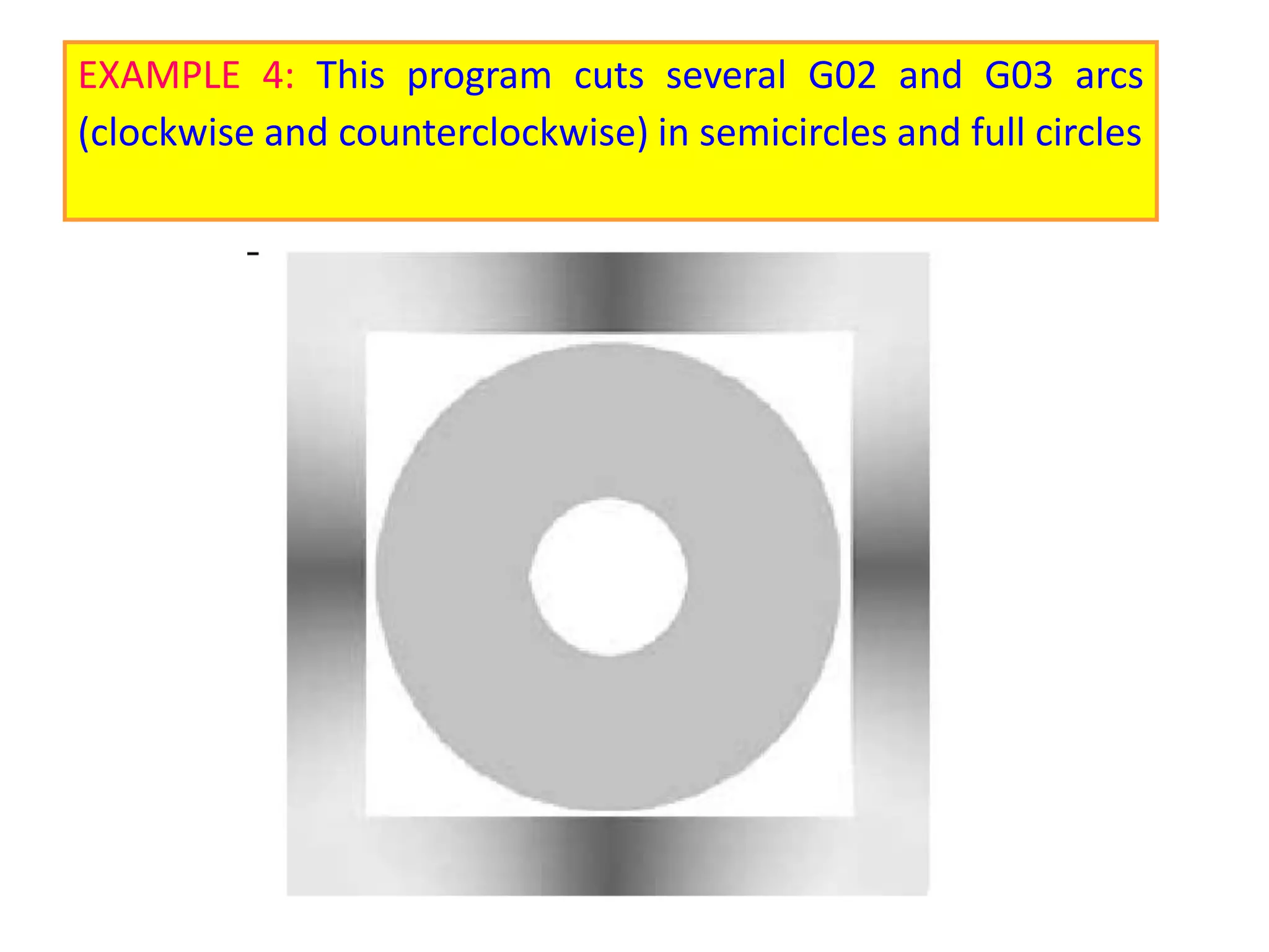
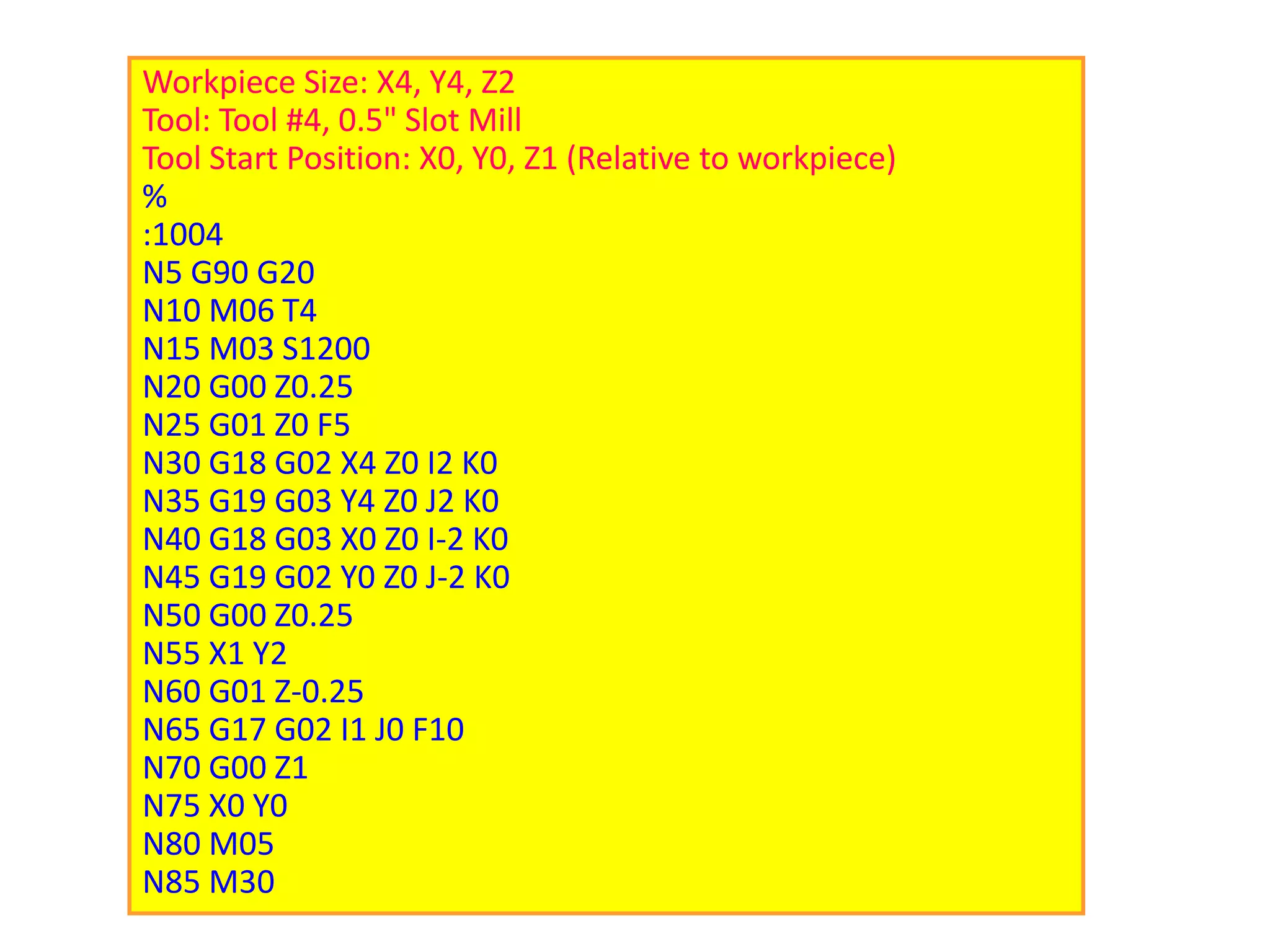
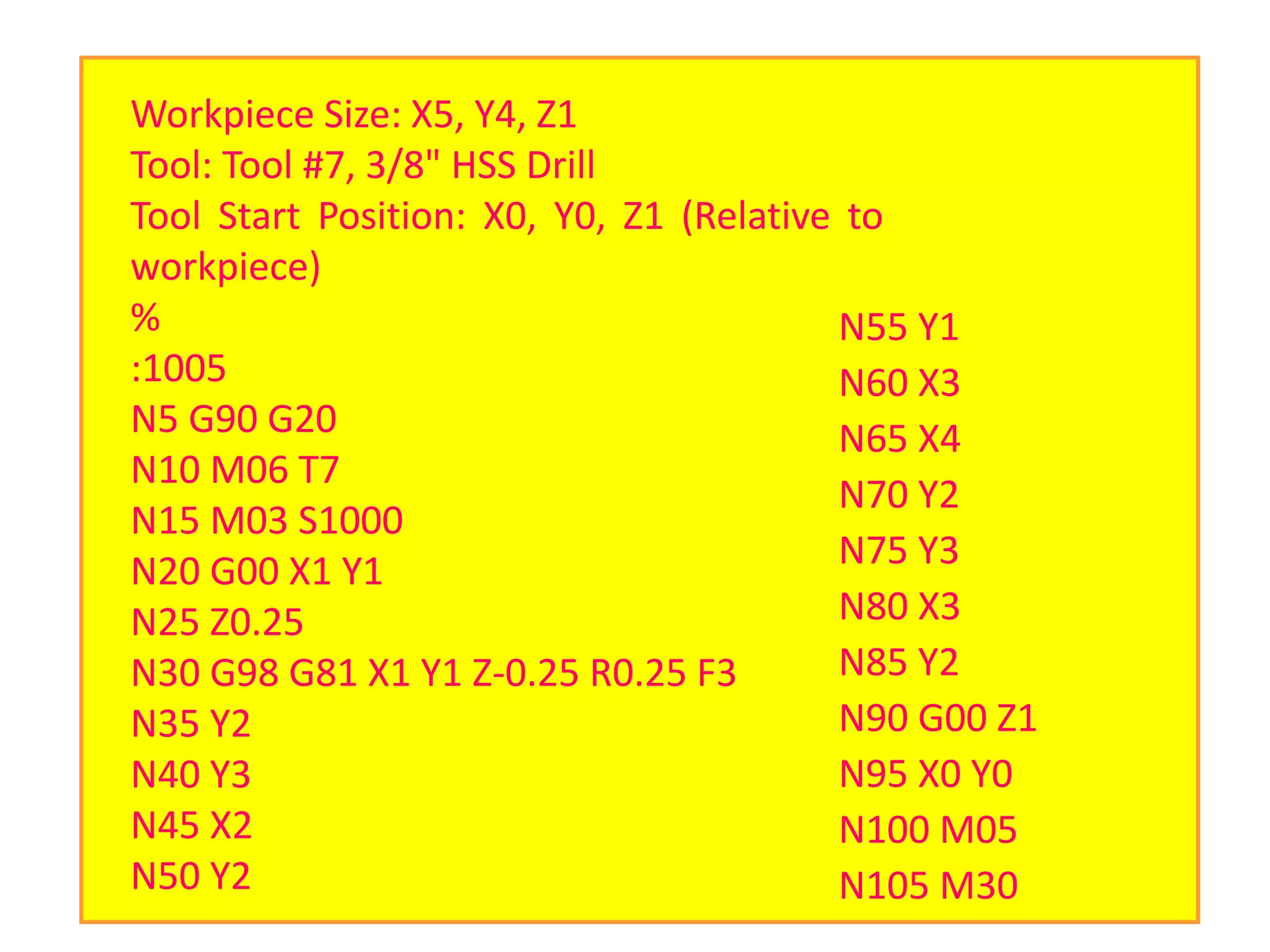
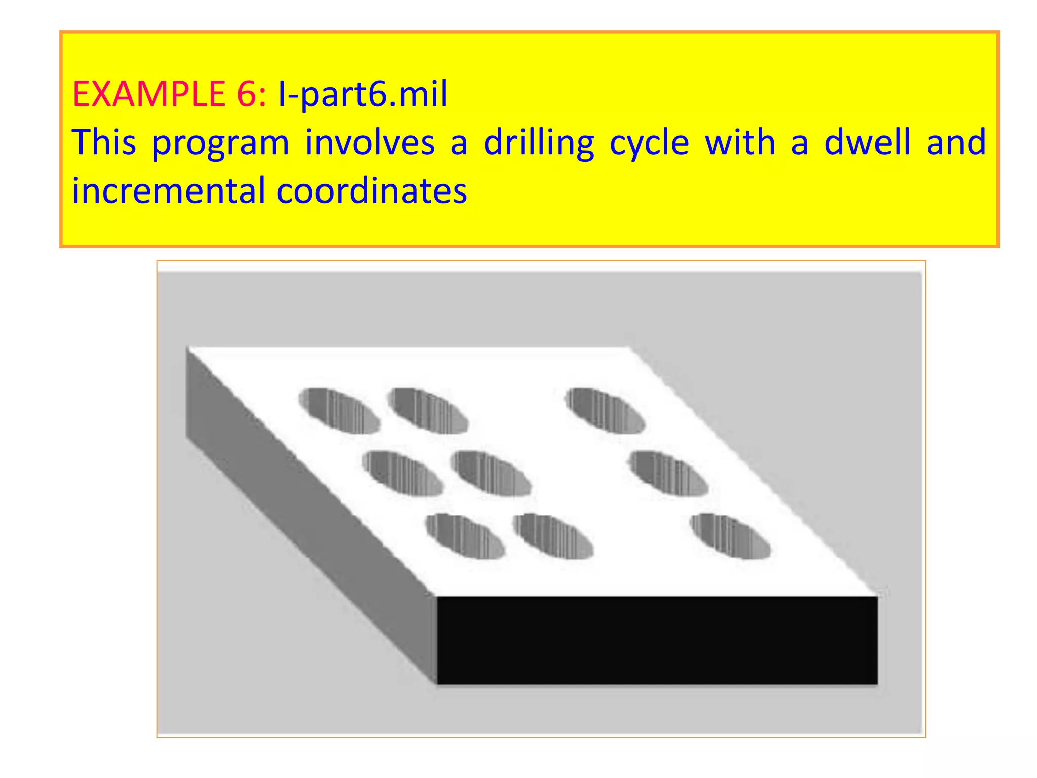
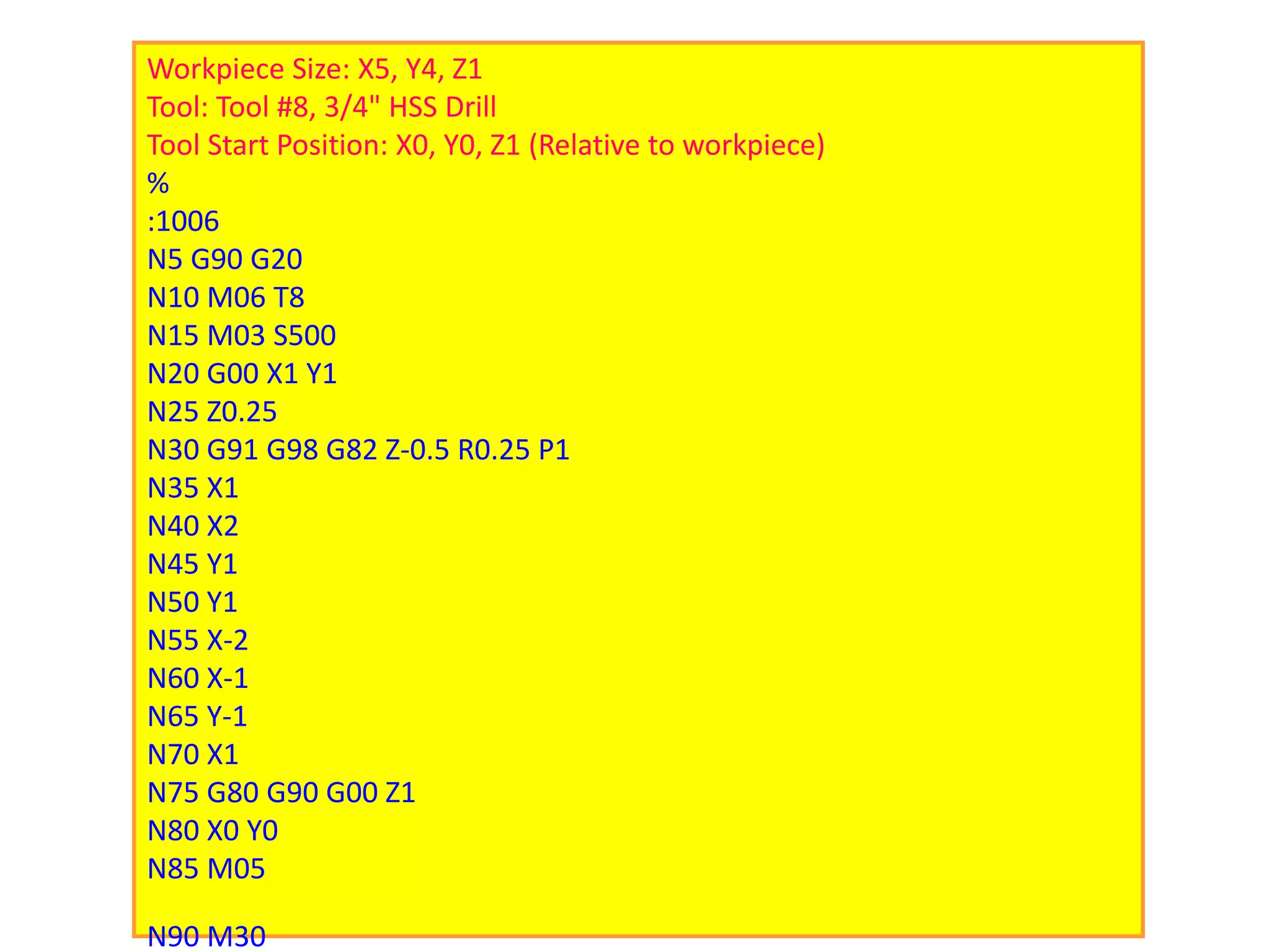
This document provides information on programming CNC milling machines. It discusses five categories of programming commands and techniques needed to maximize the power of modern CNC milling machines: 1) basic programming commands, 2) compensating offsets, 3) fixed cycles, 4) macro and subroutine programs, and 5) advanced programming features. It also provides details on specific programming codes like G-codes for tool motions and M-codes for miscellaneous functions. Sample programs are provided to demonstrate linear, circular and arc feed moves.
Modern precision manufacturing demands extreme dimensional accuracy and surface finish.Such performance is very difficult to achieve manually, if not impossible, even with expert operators. In cases where it is possible, it takes much higher time due to the need for frequent dimensional measurement to prevent overcutting. It is thus obvious that automated motion control would replace manual “handwheel” control in modern manufacturing. Development of computer numerically controlled (CNC) machines has also made possible the automation of the machining processes with flexibility to handle production of small to medium batch of parts. In the 1940s when the U.S. Air Force perceived the need to manufacture complex parts for highspeed aircraft. This led to the development of computer-based automatic machine tool controls also known as the Numerical Control (NC) systems. Commercial production of NC machine tools started around the fifties and sixties around the world. Note that at this time the microprocessor has not yet been invented. Initially, the CNC technology was applied on lathes, milling machines, etc. which could perform a single type of metal cutting operation. Later, attempt was made to handle a variety of workpieces that may require several different types machining operations and to finish them in a single set-up. Thus CNC machining Centres capable of performing multiple operations were developed. To start with, CNC machining centres were developed for machining prismatic components combining operations like milling, drilling, boring and tapping. Gradually machines for manufacturing cylindrical components, called turning centers were developed.
Automatically controlling a machine tool based on a set of pre-programmed machining and movement instructions is known as numerical control, or NC.In a typical NC system the motion and machining instructions and the related numerical data, together called a part program, used to be written on a punched tape. The part program is arranged in the form of blocks of information, each related to a particular operation in a sequence
of operations needed for producing a mechanical component. The punched tape used to be read one block at a time. Each block contained, in a particular syntax, information needed for processing a particular machining instruction such as, the segment length, its cutting speed, feed, etc. These pieces of information were related to the final dimensions of the workpiece (length, width, and radii of circles) and the contour forms (linear, circular, or other) as per the drawing. Based on these dimensions, motion commands were given separately for each axis of motion. Other instructions and related machining parameters, such as cutting speed, feed rate, as well as auxiliary functions related to coolant flow, spindle speed, part clamping, are also provided in part programs depending on manufacturing specifications such as tolerance and surface finish. Punched tapes are mostly obsolete.
Cosmetic shop management system project report.pdfKamal Acharya
Buying new cosmetic products is difficult. It can even be scary for those who have sensitive skin and are prone to skin trouble. The information needed to alleviate this problem is on the back of each product, but it's thought to interpret those ingredient lists unless you have a background in chemistry.
Instead of buying and hoping for the best, we can use data science to help us predict which products may be good fits for us. It includes various function programs to do the above mentioned tasks.
Data file handling has been effectively used in the program.
The automated cosmetic shop management system should deal with the automation of general workflow and administration process of the shop. The main processes of the system focus on customer's request where the system is able to search the most appropriate products and deliver it to the customers. It should help the employees to quickly identify the list of cosmetic product that have reached the minimum quantity and also keep a track of expired date for each cosmetic product. It should help the employees to find the rack number in which the product is placed.It is also Faster and more efficient way.
Hybrid optimization of pumped hydro system and solar- Engr. Abdul-Azeez.pdffxintegritypublishin
Advancements in technology unveil a myriad of electrical and electronic breakthroughs geared towards efficiently harnessing limited resources to meet human energy demands. The optimization of hybrid solar PV panels and pumped hydro energy supply systems plays a pivotal role in utilizing natural resources effectively. This initiative not only benefits humanity but also fosters environmental sustainability. The study investigated the design optimization of these hybrid systems, focusing on understanding solar radiation patterns, identifying geographical influences on solar radiation, formulating a mathematical model for system optimization, and determining the optimal configuration of PV panels and pumped hydro storage. Through a comparative analysis approach and eight weeks of data collection, the study addressed key research questions related to solar radiation patterns and optimal system design. The findings highlighted regions with heightened solar radiation levels, showcasing substantial potential for power generation and emphasizing the system's efficiency. Optimizing system design significantly boosted power generation, promoted renewable energy utilization, and enhanced energy storage capacity. The study underscored the benefits of optimizing hybrid solar PV panels and pumped hydro energy supply systems for sustainable energy usage. Optimizing the design of solar PV panels and pumped hydro energy supply systems as examined across diverse climatic conditions in a developing country, not only enhances power generation but also improves the integration of renewable energy sources and boosts energy storage capacities, particularly beneficial for less economically prosperous regions. Additionally, the study provides valuable insights for advancing energy research in economically viable areas. Recommendations included conducting site-specific assessments, utilizing advanced modeling tools, implementing regular maintenance protocols, and enhancing communication among system components.
Saudi Arabia stands as a titan in the global energy landscape, renowned for its abundant oil and gas resources. It's the largest exporter of petroleum and holds some of the world's most significant reserves. Let's delve into the top 10 oil and gas projects shaping Saudi Arabia's energy future in 2024.
Explore the innovative world of trenchless pipe repair with our comprehensive guide, "The Benefits and Techniques of Trenchless Pipe Repair." This document delves into the modern methods of repairing underground pipes without the need for extensive excavation, highlighting the numerous advantages and the latest techniques used in the industry.
Learn about the cost savings, reduced environmental impact, and minimal disruption associated with trenchless technology. Discover detailed explanations of popular techniques such as pipe bursting, cured-in-place pipe (CIPP) lining, and directional drilling. Understand how these methods can be applied to various types of infrastructure, from residential plumbing to large-scale municipal systems.
Ideal for homeowners, contractors, engineers, and anyone interested in modern plumbing solutions, this guide provides valuable insights into why trenchless pipe repair is becoming the preferred choice for pipe rehabilitation. Stay informed about the latest advancements and best practices in the field.
Overview of the fundamental roles in Hydropower generation and the components involved in wider Electrical Engineering.
This paper presents the design and construction of hydroelectric dams from the hydrologist’s survey of the valley before construction, all aspects and involved disciplines, fluid dynamics, structural engineering, generation and mains frequency regulation to the very transmission of power through the network in the United Kingdom.
Author: Robbie Edward Sayers
Collaborators and co editors: Charlie Sims and Connor Healey.
(C) 2024 Robbie E. Sayers
Welcome to WIPAC Monthly the magazine brought to you by the LinkedIn Group Water Industry Process Automation & Control.
In this month's edition, along with this month's industry news to celebrate the 13 years since the group was created we have articles including
A case study of the used of Advanced Process Control at the Wastewater Treatment works at Lleida in Spain
A look back on an article on smart wastewater networks in order to see how the industry has measured up in the interim around the adoption of Digital Transformation in the Water Industry.
Water scarcity is the lack of fresh water resources to meet the standard water demand. There are two type of water scarcity. One is physical. The other is economic water scarcity.
1. IE433 CAD/CAM
Computer Aided Design and
Computer Aided Manufacturing
Part-10
CNC Milling Programming
Industrial Engineering Department
King Saud University
2. To maximize the power of modern CNC
milling machines, a programmer has to
master the following five categories of
programming command codes and
techniques:
1. Basic programming commands.
2. Compensating an offset.
3. Fixed cycles.
4. Macro and subroutine programs.
5. Advanced programming features.
3. 1. Basic programming commands.
• Motion commands (G00, G01, G02, G03)
• Plane selection (G17, G18, G19)
• Positioning system selection (G90, 091)
• Unit selection (G70 or G20, G71 or G21)
• Work coordinate setting (G92)
• Reference point return (G28, G29, G30)
• Tool selection and change (Txx M06)
• Feed selection and input (Fxxx.xx, G94, 095)
• Spindle speed selection and control (Sxxxx, M03, M04,
M05)
• Miscellaneous functions (M00, M01, M02, M07, M08, M09,
M30)
4. 2. Compensation and offset. The use of compensation and offset
functions in defining work coordinate systems, performing tool
diameter compensations, and accommodating tool length
differences often results in reduced programming effort. The
main compensation and offset functions are
• Work coordinate compensation (G54-G59)
• Tool diameter (radius) compensation (G40, G41, G42)
• Tool length offset (G43, G44, G49)
3. Fixed cycles. The purpose of a fixed cycle is to execute a series
of repetitive machining operations with a single block
command. Fixed cycles may be classified into the following
three categories:
• Standard fixed cycles (G80-G89)
• Special fixed cycles
• User-defined fixed cycles
5. 4. Macro and subroutine programming. Most modem CNC controls furnish the
power of computer programming to define variables, perform arithmetic
operations, execute logical decisions, and so on. These features allow easy
implementation of repetitive machining patterns and complex workpiece
shapes that can be defined mathematically.
5. Advanced programming features. These commands are dependent on user
control. They are used to simplify programming effort and reduce
programming time and program size. Typical features include scaling,
rotation, and mirror image.
6. G-codes are preparatory functions that involve actual tool moves (for example,
control of the machine). These include rapid moves, feed moves, radial feed
moves, dwells, and roughing and profiling cycles.
Most G-codes described here are modal, meaning that they
remain active until canceled by another G-code. The
following codes are described in more detail in the
following sections.
CNC Milling G-Codes
7. G00 Positioning in rapid Modal
G01 Linear interpolation Modal
G02 Circular interpolation (CW) Modal
G03 Circular interpolation (CCW) Modal
G04 Dwell
G17 XY plane Modal
G18 XZ plane Modal
G19 YZ plane Modal
G20/G70 Inch units Modal
CNC Milling G-Codes
8. G21/G71 Metric units Modal
G28 Automatic return to reference point
G29 Automatic return from reference point
G40 Cutter compensation cancel Modal
G41 Cutter compensation left Modal
G42 Cutter compensation right Modal
G43 Tool length compensation (plus) Modal
G44 Tool length compensation (minus) Modal
G49 Tool length compensation cancel Modal
G54-G59 Workpiece coordinate settings Modal
CNC Milling G-Codes
10. CNC Milling M-CODES
M-codes are miscellaneous functions that include actions necessary fo
machining but not those that are actual tool movements. That is, they are
auxiliary functions, such as spindle on and off, tool changes, coolant on
and off, program stops, and similar related functions. The following codes
are described in more detail in the following sections.
M00 Program stop
M01 Optional program stop
M02 Program end
M03 Spindle on clockwise
M04 Spindle on counterclockwise
11. M05 Spindle stop
M06 Tool change
M08 Coolant on
M09 Coolant off
M10 Clamps on
M11 Clamps off
M30 Program end, reset to start
M98 Call subroutine command
M99 Return from subroutine command
Block Skip Option to skip blocks that begin with ‘/’
Comments Comments may be included in blocks with
round brackets ‘(’ ‘)’
CNC Milling M-CODES
12. Tool Motion Command - G00 Positioning in Rapid
Format: N_ G00 X_ Y_ Z_
The G00 command is a rapid
tool move. A rapid tool move
is used to move the tool
linearly from position to
position without cutting any
material. This command is
not to be used for cutting any
material, as to do so would
seriously damage the tool
and ruin the workpiece. It is a
modal command, remaining
in effect until canceled by
another G-Code command
13. The G00 command is used to move the tool
quickly from one point to another without cutting,
thus allowing for quick tool positioning.
14. The G00 rapid move should have two distinct movements to
ensure that vertical moves are always separate from
horizontal moves. In a typical rapid move toward the part,
the tool first rapids in the flat, horizontal XY plane. Then, it
feeds down in the Z axis. When rapiding out of a part, the
G00 command always goes up in the Z axis first, then
laterally in the XY plane.
15. As this diagram shows, if the basic rules are not
followed, an accident can result. Improper use of
G00 often occurs because clamps are not taken
into consideration. Following the basic rules will
reduce any chance of error.
16. EXAMPLE:
N25 G00 X2.5 Y4.75 (Rapid to X2.5,Y4.75)
N30 Z0.1 (Rapid down to Z0.1)
Depending on where the tool is located, there are two basic rules to
follow for safety’s sake:
• If the Z value represents a cutting move in the negative direction, the X and Y axes
should be executed first.
• If the Z value represents a move in the positive direction, the X and Y axes should
be executed last.
17. Sample Program :
Workpiece Size: X6,Y4,Z1
Tool: Tool #2, 1/4" Slot Drill
Tool Start Position: X0,Y0,Z1
% (Program start flag)
:1001 (Program number 1001)
N5 G90 G20 (Absolute and inch programming)
N10 M06 T2 (Tool change, Tool #2)
N15 M03 S1200 (Spindle on CW, at 1200 rpm)
N20 G00 X1 Y1 (Rapid over to X1,Y1)
N25 Z0.1 (Rapid down to Z0.1)
N30 G01 Z-0.25 F5 (Feed move down to a depth of 0.25 in.)
N35 Y3 (Feed move to Y3)
N40 X5 (Feed to X5)
N45 X1 Y1 Z-0.125 (Feed to X1,Y1,Z–0.125)
N50 G00 Z1 (Rapid up to Z1)
N55 X0 Y0 (Rapid over to X0,Y0)
N60 M05 (Spindle off)
N65 M30 (End of program)
18. G01 Linear Interpolation
Format: N_ G01 X_ Y_ Z_ F_
The G01 command is
specifically for the
linear removal of
material from a
workpiece, in any
combination of the X, Y,
or Z axes. The machine
tool follows a linear
trajectory.
The G01 is modal and
requires a user variable
feedrate (designated by
the letter F followed by
a number).
19. Linear Interpolation,
or straight-line feed
moves, on the flat XY
plane (no Z values
are specified).
G01 command,
using multi-axis feed
moves. All diagonal
feed moves are a
result of a G01
command, where
two or more axes
are used at once.
20. Sample Program (G01):
Workpiece Size: X4, Y3, Z1
Tool: Tool #3, 3/8" Slot Drill
Tool Start Position: X0, Y0, Z1
% (Program start flag)
:1002 (Program #1002)
N5 G90 G20 (Block #5, absolute in inches)
N10 M06 T3 (Tool change to Tool #3)
N15 M03 S1250 (Spindle on CW at 1250 rpm)
N20 G00 X1.0 Y1.0 (Rapid over to X1,Y1)
N25 Z0.1 (Rapid down to Z0.1)
N30 G01 Z-0.125 F5 (Feed down to Z–0.125 at 5 ipm)
N35 X3 Y2 F10 (Feed diagonally to X3,Y2 at 10 ipm)
N40 G00 Z1.0 (Rapid up to Z1)
N45 X0.0 Y0.0 (Rapid over to X0,Y0)
N50 M05 (Spindle off)
N55 M30 (Program end)
21. Format: N_ G02 X_ Y_ Z_ I_ J_ K_ F_
or N_ G02 X_ Y_ Z_ R_ F_
G02 Circular Interpolation (clockwise)
Circular Interpolation is
more commonly known as
radial (or arc) feed moves.
The G02 command is
specifically used for all
clockwise radial feed
moves, whether they are
quadratic arcs, partial
arcs, or complete circles,
as long as they lie in any
one plane.
The G02 command is
modal and is subject to a
user-definable feed rate.
22. The G02 command requires
an endpoint and a radius in
order to cut the arc. The
start point of this arc is
(X1,Y4) and the endpoint is
(X4,Y1). To find the radius,
simply measure the
incremental distance from
the start point to the center
point. This radius is written
in terms of the X and Y
distances. To avoid
confusion, these values are
assigned variables, called I
and J, respectively.
G02 Circular Interpolation (cont'd.)
23. EXAMPLE: G02 X2 Y1 I0 J-1
The G02 command requires an endpoint and a radius in order to cut the arc.
The start point of this arc is (X1, Y2) and the end-point is (X2, Y1). To find the
radius, simply measure the relative, (or incremental), distance from the start
point to the center point. This radius is written in terms of the X and Y
distances. To avoid confusion, these values are assigned variables called I and
J, respectively.
24. EXAMPLE: G02 X2 Y1 R1
You can also specify G02 by entering the X and Y endpoints and then R for the
radius.
Note: The use of an R value for the radius of an arc is limited to a maximum
movement of 90°.
An easy way to determine the radius values (the I and J values) is by making a small
chart:
Center point X1 Y1
Start point X1 Y2
Radius I0 J-1
Finding the I and J values is easier than it first seems. Follow these steps:
1. Write the X and Y coordinates of the arc’s center point.
2. Below these coordinates, write the X and Y coordinates of the arc’s start
point.
3. Draw a line below this to separate the two areas to perform the subtraction.
Result: G02 X2 Y1 I0 J-1 F5
4. To find the I value, calculate the difference between the arc’s start point and
center point in the X direction. In this case, both X values are 1. Hence there is no
difference between them, so the I value is 0. To find the J value, calculate the
difference between the arc’s start point and center point in the Y direction. In this
26. G03 CIRCULAR INTERPOLATION (CCW)
Format: N_ G03 X_ Y_ Z_ I_ J_ K_ F_ (I, J, K specify the radius)
The G03 command is
used for all
counterclockwise radial
feed moves, whether
they are quadratic arcs,
partial arcs, or complete
circles, as long as they
lie in any one plane.
The G03 command is
modal and is subject to
a user-definable feed
rate
27. EXAMPLE: G03 X1 Y1 I0 J-1
The G03 command requires an endpoint and a radius in order to cut the arc.
(See Fig. 5.7.) The start point of this arc is (X2, Y2) and the end-point is (X1, Y1).
To find the radius, simply measure the incremental distance from the start point
to the center point of the arc. This radius is written in terms of the X and Y
distances. To avoid confusion, these values are assigned variables called I and J,
respectively.
28. EXAMPLE: G03 X1 Y1 R1
You can also specify G03 by entering the X and Y endpoints and then R for the
radius.
Note: The use of an R value for the radius of an arc is limited to a maximum
movement of 90°. An easy way to determine the radius values (the I and J values) is
to make a small chart as follows.
Center point X2 Y1
Start point X2 Y2
Radius I0 J-1
Finding the I and J values is easier than it first seems. Follow these steps:
1. Write the X and Y coordinates of the arc’s center point.
2. Below these coordinates, write the X and Y coordinates of the arc’s start point.
3. Draw a line below this to separate the two areas to perform the subtraction.
4. To find the I value, calculate the difference between the arc’s start point and
center point in the X direction. In this case, both X values are 2. Hence there is no
difference between them, so the I value is 0. To find the J value, calculate the
difference between the arc’s start point and center point in the Y direction. In this
case, the difference between Y2 and Y1 is down 1 inch, so the J value is –1.
Result: G03 X1 Y1 I0 J-1
29. G03 Circular Interpolation (cont'd)
The G03 command requires an
endpoint and a radius in order to
cut the arc. The start point of this
arc is (X4,Y1) and the endpoint
is(X1,Y4). To find the radius,
simply measure the incremental
distance from the start point to
the center point. This radius is
written in terms of the X and Y
distances. To avoid confusion,
these values are assigned
variables I and J, respectively.
30. NOTE: Programming the G02 and G03 commands
with an R value is reserved only for arcs less than or
equal to 90 degrees. The more common method
involves the use of trigonometry to solve for the I, J,
or K values.
31. Sample Program (G03).
Workpiece Size: X4, Y4, Z0.25
Tool: Tool #2, 1/4" Slot Drill
Tool Start Position: X0, Y0, Z1
%
:1004
N5 G90 G20
N10 M06 T2
N15 M03 S1200
N20 G00 X2 Y0.5
N25 Z0.125
N30 G01 Z-0.125 F5
N35 X3 F15
N40 G03 X3.5 Y1 R0.5 (G03 arc using R value)
N45 G01 Y3
N50 G03 X3 Y3.5 I-0.5 J0 (G03 arc using I and J)
N55 G01 X2
N60 G03 X2 Y1.5 I0 J-1 (180° arc using I and J)
N65 G01 Y0.5
N70 G00 Z0.1
N75 X1.5 Y2.5
N80 G01 Z-0.25 F5
N85 G03 X1.5 Y2.5 I0.5 J0 (Full circle using I and J)
N90 G00 Z1
N95 X0 Y0
N100 M05
N105 M30
32. Command Format with IJK Method
(GI7) G02 (or G03) Xx Yy li Ji Ff on XY-plane
(G18) G02 (or G03) Xx Zz li Kk Ff on ZX-plane
(G19) G02 (or G03) Yy Zz Jj Kk Ff on YZ-plane
Command Format with R Method
(GI7) G02 (or G03) Xx Yy Rr Ff on XY-plane
(G18) G02 (or G03) Xx Zz Rr Ff on ZX-plane
(G19) G02 (or G03) Yy Zz Rr Ff on YZ-plane
33. G04 DWELL
Format: N_ G04 P_
The G04 command is
a nonmodal dwell
command that halts
all axis movement for
a specified time while
the spindle continues
revolving at the
specified rpm. A dwell
is used largely in
drilling operations
and after plunge
moves, which allows
for the clearance of
chips .
34. Sample Program (G04):
Workpiece Size: X3.5, Y2, Z0.5
Tool: Tool #1, 1/8" Slot Mill
Tool Start Position: X0, Y0, Z1
% (Program start flag)
:1005 (Program #1005)
N5 G90 G20 (Absolute programming in inch mode)
N10 M06 T1 (Tool change to Tool #1)
N15 M03 S1300 (Spindle on CW at 1300 rpm)
N20 G00 X3 Y1 Z0.1 (Rapid to X3,Y1,Z0.1)
N25 G01 Z-0.125 F5.0 (Feed down to Z–0.125 at 5 ipm)
N30 G04 P2 (Dwell for 2 seconds)
N35 G00 X2 Z0.1 (Rapid up to 0.1)
N33 X2 (Rapid to X2)
N40 G01 Z-0.125 F5.0 (Feed down to Z–0.125)
N45 G04 P1 (Dwell for 1 second)
N50 G00 Z1.0 (Rapid out to Z1)
N55 X0. Y0. (Rapid to X0, Y0)
N60 M05 (Spindle off)
N65 M30 (Program end)
40. G20 or G70 Inch Units
Format: N_ G20 or G70
The G20 or G70 command defaults the
system to inch units. When a program is
being run and the G20 command is
encountered, all coordinates are stated as
inch units. This command is usually found
at the beginning of a program. However,
on some controllers it can be used to
switch from metric units in the middle of a
program.
41. G21 or G71 Metric, or SI, Units
Format: N_ G21 or G71
The G21 or G71 command defaults the
system to metric units. When a program is
being run and the G21 command is
encountered, all coordinates are stated in
as millimeter units. This command is
usually found at the beginning of a
program. However, it can be used to
switch between metric and inch units in
the middle of a program.
42. G28 Automatic Return to Reference
Format: N_ G28 X_ Y_ Z_
The G28 command is
primarily used before
automatic tool
changing. It allows
the existing tool to be
positioned to the
predefined reference
point automatically
via an intermediate
position. This ensures
that when the tool
changer is engaged, it
is properly aligned
with the spindle head.
NOTE: When this command is being used, it is
advisable for safety reasons to cancel any tool
offset or cutter compensation.
43. G29 Automatic Return from Reference
Format: N_ G29 X_ Y_ Z_
The G29 command
can be used
immediately after an
automatic tool
change. It allows the
new tool to be
returned from the
predefined reference
point to the
specified point via
an intermediate
point specified by
the previous G28
command.
NOTE: When this command is being used, it is
advisable for safety reasons to cancel any tool
offset or cutter compensation.
44. G40 Cutter Compensation Cancel
Format: N_ G40
Usually, CNC programs are written so that the tool center
follows the toolpath. Cutter compensation is used whenever
tool centerline programming is difficult. It is also used to
compensate for significant tool wear or tool substitution. The
G40 command cancels any cutter compensation that was
applied to the tool during a program and acts as a safeguard to
cancel any cutter compensation applied to a previous program
or G-codes.
NOTE: Cutter compensation is modal, so it must be canceled
when it is no longer needed. This is the sole function of the
G40 command
45. G41 Cutter Compensation Left
Format: N_ G41 D_
The G41 command
compensates the cutter a
specified distance to the
left-hand side of the
programmed tool path. It is
used to compensate for
excessive tool wear or
substitute a tool to profile a
part.
The G41 command is
modal, so it compensates
each successive tool move
the same specified distance
until it is overridden by a
G40 command or receives a
different offset.
48. G42 CUTTER COMPENSATION RIGHT
Format: N_ G42 D_
The G42 command
compensates the cutter a
specified distance to the
right-hand side of the
programmed tool path. It
is used to compensate for
excessive tool wear or
substitute a tool to profile
a part. The G42 command
is modal, so it
compensates each
successive tool move the
same specified distance
until it is overridden by a
G40 command or receives
a different offset.
51. G43 Tool Length Compensation (Plus)
Format: N_ G43 H_
The G43 command
compensates for tool
length in a positive
direction. It is important
to realize that different
tools will have varying
lengths, and when tools
are changed in a program,
any variation in tool length
will throw the origin out
of zero. To prevent this,
the difference in tool
length should be
compensated for.
53. G44 Tool Length Compensation (Minus)
Format: N_ G44 H_
The G44 command
compensates for tool
length in a minus
direction. It is important
to realize that different
tools will have varying
lengths, and when tools
are changed in a program,
any variation in tool length
will throw the origin out
of zero. To prevent this,
the difference in tool
length should be
compensated for.
55. G49 Tool Length Compensation Cancel
Format: N_ G49
The G49 command cancels all previous cutter length offset commands. Because the
G43 and G44 commands are modal, they will remain active until canceled by the
G49 command. It is important to keep this in mind; forgetting that a tool has been
offset can cause the cutter to crash into the workpiece.
56. G54–G59 Workpiece Coordinate System
Format: N_ G54 through G59
The G54 – G59 commands are
used to reposition the origin
per a user- defined working
coordinate system. In CNCez six
register sets in the controller
hold the values for the working
coordinate systems. The G54 –
G59 commands are very useful
when multiple workpiece
fixtures are used. On real CNC
controllers these values are
held in parameter fields which
are normally set in the
parameters entry screen of the
controller.
57. G73 High-Speed Peck Drilling Cycle
Format: N_ G73 X_ Y_ Z_ R_ Q_ F_
During a G73 high-speed peck
drilling cycle, the tool feeds in
to the peck distance or depth
of cut, then retracts a small
pre-determined distance,
which is the chip-breaking
process, and then feeds to the
next peck, which takes the tool
deeper. This process is
repeated until the final Z depth
is reached. Because the tool
doesn't retract fully from the
hole, as in the G83 cycle, it
minimizes cycle time and
improves total part machining
time.
58. G80 Cancel Canned Cycles
Format: N_ G80
The G80 command cancels all previous canned cycle commands. Because the
canned cycles are modal (refer to the canned cycles on the following pages), they
will remain active until canceled by the G80 command. Canned cycles include
tapping, boring, spot facing, and drilling.
Note: On most controllers the G00 command will also cancel any canned cycles.
59. G81 Drilling Cycle
Format: N_ G81 X_ Y_ Z_ R_ F_
The G81 command
invokes a drill cycle at
specified locations. This
cycle can be used for
bolt holes, drilled
patterns, and mold
sprues, among other
tasks. This command is
modal and so remains
active until overridden
by another move
command or canceled
by the G80 command.
Invoking the G81 command requires
invoking the Z initial plane, Z depth
and Z retract plane parameters.
60. G82 Spot Drilling or Counter Boring Cycle
Format: N_ G82 X_ Y_ Z_ R_ P_ F_
This cycle follows the same
operating procedures as the
G81 drilling cycle, with the
addition of a dwell. The
dwell is a pause during
which the Z axis stops
moving but the spindle
continues rotating. This
pause allows for chip
clearing and a finer finish on
the hole. The dwell time is
measured in seconds.
The dwell is specified by the
P letter address, followed by
the dwell time in seconds.
The same Z levels apply to the G82
cycle as to the G81 cycle: Z initial
plane, Z depth and Z retract.
61. G83 Deep Hole Drilling Cycle
Format: N_ G83 X_ Y_ Z_ R_ Q_ F_
The G83 command involves
individual peck moves in each
drilling operation. When this
command is invoked, the tool
positions itself as in a
standard G81 drill cycle. The
peck is the only action that
distinguishes the deep hole
drilling cycle from the G81
cycle. When pecking, the tool
feeds in the specified distance
(peck distance or depth of
cut), then rapids back out to
the Z Retract plane. The next
peck takes the tool deeper,
and then it rapids out of the
hole. This process is repeated
until the final Z depth is
reached.
In the G83 cycle, Q is the incremental depth of
cut.
62. G90 Absolute Positioning
Format: N_ G90
The G90 command defaults the system to
accept all coordinates as absolute
coordinates. These coordinates are
measured from a fixed origin (X0, Y0, Z0)
and expressed in terms of X, Y, and Z
distances.
63. G91 Incremental Positioning
Format: N_ G91
The G91 command defaults the system to
accept all coordinates as incremental, or
relative, coordinates.
64. G92 Reposition Origin Point
Format: N_ G92 X_ Y_ Z_
The G92 command is
used to reposition the
origin point. The origin
point is not a physical
spot on the machine
tool, but rather a
reference point to which
the coordinates relate.
Generally, the origin
point is located at a
prominent point or
object (for example, front
top left corner of the
part) so that it is easier to
measure from.
65. G98 Set Initial Plane Rapid Default
Format: N_ G98
The G98 command
forces the tool to return
to the Z initial plane a
drilling operation. This
forces the tool up and
out of the workpiece.
This setting is normally
used when a workpiece
has clamps or other
obstacles that could
interfere with tool
movement. The G98
command is also the
system default.
66. G99 Set Rapid to Retract Plane
Format: N_ G99
The G99 command forces
the tool to return to the
retract plane after a drilling
operation. This forces the
tool up and out of the
workpiece to the retract
plane specified in the drilling
cycle, overriding the system
default. This command is
usually used on drilling cycles
within a pocket, or on
workpieces that do not have
surface obstacles. It is
quicker than the G98
command because the tool
moves only to the retract
plane.
67. M-codes are miscellaneous functions that include actions
necessary for machining but not those that are actual tool
movements (for example, auxiliary functions). They include
actions such as spindle on and off, tool changes, coolant on
and off, program stops, and similar related functions.
CNC Milling – M- Codes
68. M00 Program stop
M01 Optional program stop
M02 Program end
M03 Spindle on clockwise
M04 Spindle on counterclockwise
M05 Spindle stop
M06 Tool change
M08 Coolant on
M09 Coolant off
M10 Clamps on
M11 Clamps off
M30 Program end, reset to start
M98 Call subroutine command
M99 Return from subroutine command
Block Skip Option to skip blocks that begin with ‘/’
Comments Comments may be included in blocks with round brackets
‘(’ ‘)’
M-Codes
69. M00 - Program stop
Format: N_ M00
The M00 command is a temporary program stop function. When
it is executed, all functions are temporarily stopped and will not
restart unless and until prompted by user input.
This command can be used in lengthy programs to stop the
program in order to clear chips, take measurements, or adjust
clamps, coolant hoses, and so on.
M01 Optional Program Stop
Format: N_ M01
If the Optional Stop switch is set to ON, the program will stop
when it encounters in an M01command. Both real CNC
controllers and the CNCez simulators have this feature.
70. M02 PROGRAM END
Format: N_ M02
The M02 command indicates an end of the main program cycle operation. Upon
encountering the M02 command, the MCU switches off all machine operations (for
example, spindle, coolant, all axes, and any auxiliaries), terminating the program.
This command appears on the last line of the program.
Sample Program (M02):
Workpiece Size: X4, Y3, Z1
Tool: Tool #2, 1/4" Slot Drill
Tool Start Position: X0, Y0, Z1
%
:1003
N5 G90 G20
N10 M06 T2
N15 M03 S1200
N20 G00 X1 Y1
N25 Z0.1
N30 G01 Z-.125 F5
N35 X3 F15
N40 G00 Z1
N45 X0 Y0
N50 M05
N55 M02 (Program end)
71. M03 SPINDLE ON CLOCKWISE
Format: N_ M03 S_
The M03 command switches the spindle on in a clockwise rotation. The spindle
speed is designated by the S letter address, followed by the spindle speed in
revolutions per minute
72. M04 SPINDLE ON COUNTERCLOCKWISE
Format: N_ M04 S_
The M04 command switches the spindle on in a counterclockwise
rotation. The spindle speed is designated by the S letter address,
followed by the spindle speed in revolutions per minute.
73. M05 SPINDLE STOP
Format: N_ M05
The M05 command turns the spindle off. Although other M-
codes turn off all functions (for example, M00 and M01), this
command is dedicated to shutting the spindle off directly. The
M05 command appears at the end of a program.
M06 TOOL CHANGE
Format: N_ M06 T_
The M06 command halts all program operations for a tool
change. It is actually a two-fold command. First, it stops all
machine operations—for example, the spindle is turned off and
oriented for the tool change, and all axes motion stops—so that
it is safe to change the tool. Second, it actually changes the tool
75. M07/M08 COOLANT ON
Format: N_ M07 or N_ M08
The M07 and M08 commands switch on the coolant flow.
M09 COOLANT OFF
Format: N_ M09
The M09 command shuts off the coolant flow. The coolant should
be shut off prior to tool changes or when you are rapiding the tool
over long distances.
76. M08 Coolant On or M09 Coolant Off
Format: N_ M08 or N_ M09
77. M10 CLAMPS ON
Format: N_ M10
The M10 command turns on the automatic clamps to secure
the workpiece. Automatic clamps can be pneumatic,
hydraulic, or electromechanical. Not all CNC machines have
automatic clamps, but the option exists and the actual code
will vary by machine tool make and model.
78. M11 CLAMPS OFF
Format: N_ M11
The M11 command releases the automatic clamps so that the
work-piece may be removed and the next blank inserted. The
automatic clamps may be pneumatic, hydraulic, or
electromechanical, depending on the application.
80. M30 PROGRAM END, RESET TO START
Format: N_ M30
The M30 command indicates the end of the program data. In
other words, no more program commands follow it. This is a
remnant of the older NC machines, which could not
differentiate between one program and the next, so an End
of Data command was developed. Now the M30 is used to
end the program and reset it to the start.
81. M98 CALL SUBPROGRAM
Format: N_ M98 P_
The M98 function is used to call a subroutine or subprogram.
Execution is halted in the main program and started on the
program referenced by the P letter address value. For example,
N15 M98 P1003 would call program :1003, either from within
the current CNC program file or from an external CNC program
file. Machine status is maintained when a sub-program is called.
This is especially useful in family parts programming or when
several operations are required on the same hole locations. In
the following sample program the subprogram is used to drill a
hole pattern, using several calls to different drill cycles. The main
program positions the machine tool at the starting location to
invoke the cycle; the subprogram then continues the pattern
85. M99 RETURN FROM SUBPROGRAM
Format: N_ M99
The M99 function is used to end or terminate the subprogram and return to
the main calling program. Execution is continued at the line immediately
following the subprogram call. It is used only at the end of the subprogram.
Sample Program M99EX10:
Workpiece Size: X5, Y5, Z1
Tool: Tool #1, 3/32" Spot Drill
Tool #2, 1/4” HSS Drill
Tool Start Position: X0, Y0, Z1
%
:1011
N5 G90 G20
N10 M06 T1
N15 M03 S1500
N20 M08 (Coolant on)
N25 G00 X1 Y1
N30 G82 X1 Y1 Z-.1 R.1 P0.5 F5 (Start of cycle)
87. Examples
This program introduces you to the Cartesian coordinate
system and absolute coordinates. Only single-axis, linear-feed
moves show the travel directions of the X, Y, and Z axe
91. Example 3:
This program introduces arcs: G02 (clockwise) and G03
(counterclockwise). These are all simple quarter quadrant arcs
with a 1-in. radius
95. EXAMPLE 5:
This program involves a simple drilling cycle with a defined
retract plane. Once the G-code for the drill cycle has been
executed, only the X and/or Y location of the remaining holes
need to be defined