Download to read offline

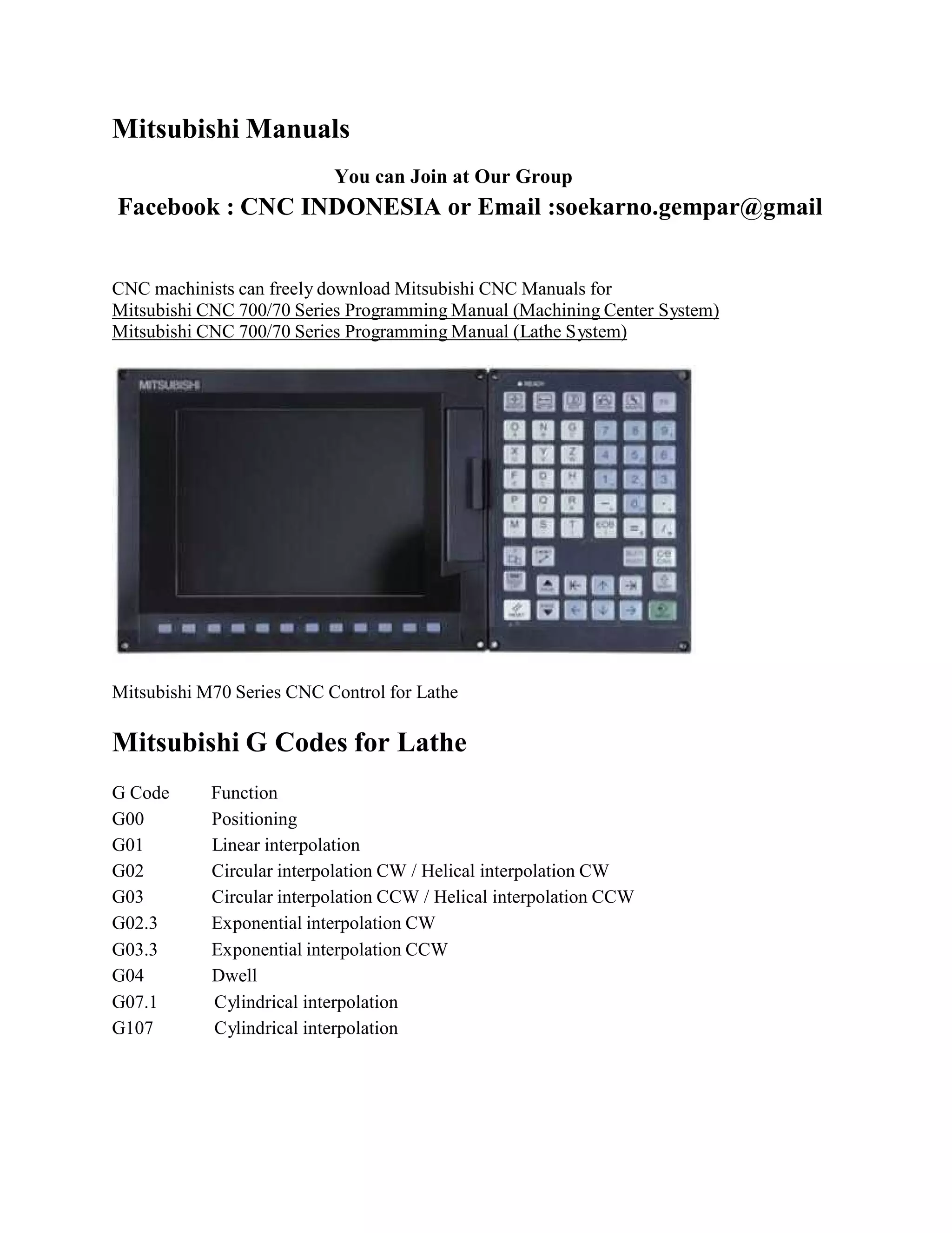
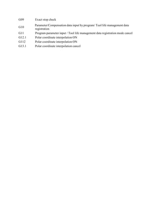
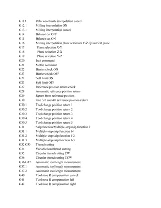
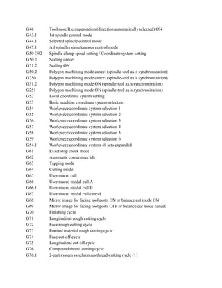
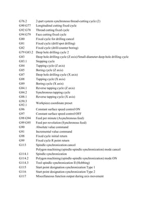

The document provides information about Mitsubishi CNC manuals for the 700/70 series, including programming guides for machining centers and lathes. It includes detailed descriptions of various G-code functions used for CNC programming, covering operations such as interpolation, tool management, and coordinate system setup. The manuals are available for download and can be accessed through a Facebook group or email.