Downloaded 849 times
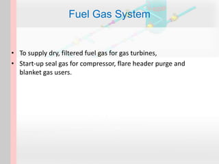
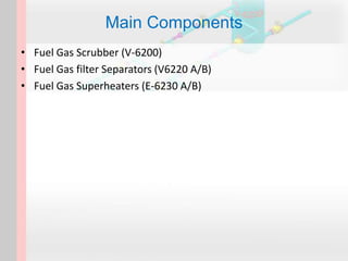
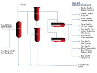

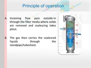
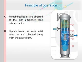


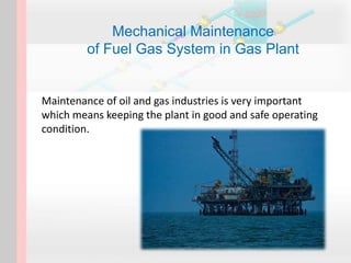


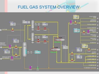
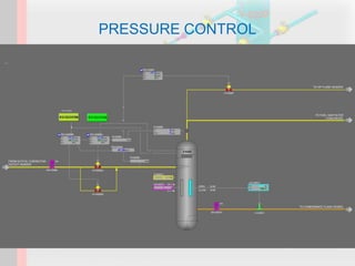
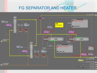


The document outlines the fuel gas system used in gas plants, detailing its components such as fuel gas scrubbers, filter separators, and superheaters, which are essential for supplying dry, filtered fuel gas for various applications. It emphasizes the importance of maintenance practices, including routine inspections and testing to ensure safe and efficient operation of the system. Additionally, it describes the operating principles and protective measures to prevent issues like overpressure and contamination in the fuel gas system.