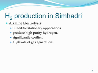
M. Nageswar Rao,
Sr.Mgr.(EMD)
Date: 09.10.2015
Venue: EDC, Simhadri
Presentation layout
 Need for Hydrogen
 Facts & Merits of Hydrogen
 Technologies of Hydrogen production
 Hydrogen generation at Simhadri
 Safety aspects
 Statutory requirements
2
Need for Hydrogen
 Generator cooling
 Stator core
 Rotor core
 Rotor winding
3
Facts about hydrogen
 Lightest element
 Atomic number 1.
 Density of Hydrogen =0.07
 Most abundant element in the Universe. Not
naturally found in atomic state on earth. Bound to
other elements as Compound.
 Normal boiling point of – 253°C (- 423°F)
 Flammable
 Colourless & Odorless
 Non Toxic & Non Corrosive
4
Merits of hydrogen
 Thermal conductivity 5 times more than air.
 Higher specific heat
 3.42 at 0 degC as compared to 0.237 of air.
 538 degC is ignition temp in air.
 Low density& light gas (14 times lighter)
 Very good heat transfer property.
 Less drag, Low windage & frictional losses.
 Better circulation.
BUT ITS MIXTURE WITH AIR IS
EXPLOSIVE
6
Technologies of H2 production
7
 Electrolysis of water
 Electro-chemical cell
 Natural H2 extraction
H2 production in Simhadri
 Alkaline Electrolysis
 Suited for stationary applications
 produce high purity hydrogen.
 significantly costlier.
 High rate of gas generation
8
Alkaline Electrolysis
9
Inputs required
 DM water (Conductivity < 1 μS/cm)
 Rectifier (Direct current)
 KOH electrolyte solution (Caustic Potash Solution
sp.gr. of 1.25 @15.5degC) – increase conductivity
 Cooling water
 Instrument Air
10
Process flow
11
Process flow
12
Main components
 Rectifiers : Make M/s HIND, (DC 9V, 2270A)
 Electrolyser (Stuart Cell)
 Gas Holders (Liquid Floating Type)
 Compressors (Diaphragm Type)
 Purification Skid
 Manifold
 Vacuum Pump
13
Rectifier
Parameter Rating
Input 3-ph, 415V ac, 45A
Output DC 9V,
2270A (20% -100% operating range),
6pulse o/p
Type of control Constant current by means of SCR
Specification IEC-146
Cooling Air forced (Rectifier & control panel)
14
Rectifier
 6-pulse centre-tap
converter with Inter
group reactor.
 It is formed by 2 no.s of 3-
ph half wave converters
with a phase shift of л
connected in parallel
through IGR.
 Each SCR conducts for
2 л /3 (л /3 if no IGR)
 IGR absorbs
instantaneous Potential
difference between
common cathodes.
15
Stuart Cell
 Sealed Unipolar type Cells
 3- plate cell having
 1 nickel plated iron anode plate
 2 iron cathode plates
 MOC: Mild Steel / IS: 2062 / 1079
 KOH solution (concentration of 28-
30%)
 Low Voltage system to ensure safe
condition (2.2 volts Each)
 Capacity : 3.75 cum/hr @2800A
 Two streams in service
 Capacity 2X 3.75 =7.5 cum/hr
 Generated H2 Gas Purity > 99.8%
16
Gas holder
 Two gas holders
 One for receive gas from
generation
 Other for supply gas to the
compressors.
 Buffer vessel
 Water sealed liquid floating
 MOC : mild steel
 Tank & Bell construction
 Operating Pressure 125 mmwc
 Limit Switches on both high and
low levels of the tank to
maintain right amount of Gas
within the vessel with all
necessary interlocks.
17
Compressors
 Diaphragm Type
 Two Stage compression
 1 st 20 kg/cm2
 2nd 170 kg/cm2
 Isothermal Process of
compression
 Hydraulic oil is the
motivating force
 Cap: 4.7 cum/hr (Each)
 Two in service , One as
stand by.
18
Purification skid
 Removal of O2 impurity in H2
gas by means of a Catalytic
purifier (Palladium based).
 Coalescing Filters to remove
moisture in H2 gas.
 Dual Tower regenerative
Desiccant Dryer (Molecular
Sieve) to achieve the necessary
Dew Point.
 Filters to remove particulate
carry over traces in the product
H2 gas
 Generated H2 gas
 purity > 99.99% ,
 Due point < - 40 Deg.C.
19
Manifold
 Filling of high purity H2 in
cylinders at high pressure @
140 kg /cm2
 Provision for connecting to
vacuum pump for ensuring
“No foreign gas/ positive
hydrogen
 Provision for venting to
atmosphere in case of purity
less than required.
 Maintain positive pressure in
hydrogen cylinder to prevent
introduction of air
20
Process parameters
21
Parameter Value
DM water conductivity < 4 μS/cm
Sp.gr. of electrolyte KOH 1.20 -1.23
Cell voltage 2.2V
Current 2000Amps
Operating Temp 50 degC
Purity >99.99%
Dew point < -40 deg C
Filled Cylinder Pressure 140kg/cm2
Generation capacity
 Generation @ 2800A
 Hydrogen (99.8%) : 7.5 cum/hr
 Oxygen : 3.75 cum/hr
 Bottling
 Hydrogen (>99.9%) : 1 Cyl @ 140 kg/cm2
 Oxygen : To vent
 Daily average : 5-6 Cyls.
22
Safety aspects
 KOH is strong Alkali , hazardous,
Use PPE Ensure Availability of
Emergency Shower
 Oxygen generated is combustible &
hence to be vented . Ensure no
open flames near venting area.
 H2 is flammable and may form
mixtures with air that are
flammable or explosive.
23
Statutory Requirements
24
License/ Testing Frequency
License from ministry of explosives
for
• Generation
• Filling
• Storage
• Night Shift operation
Expiring on
30.09.2015
Hydro static Stretch test of Cylinders
@250kg/cm2
Every 5 years
25

H2 Plant presentation-2

  • 1.
    M. Nageswar Rao, Sr.Mgr.(EMD) Date:09.10.2015 Venue: EDC, Simhadri
  • 2.
    Presentation layout  Needfor Hydrogen  Facts & Merits of Hydrogen  Technologies of Hydrogen production  Hydrogen generation at Simhadri  Safety aspects  Statutory requirements 2
  • 3.
    Need for Hydrogen Generator cooling  Stator core  Rotor core  Rotor winding 3
  • 4.
    Facts about hydrogen Lightest element  Atomic number 1.  Density of Hydrogen =0.07  Most abundant element in the Universe. Not naturally found in atomic state on earth. Bound to other elements as Compound.  Normal boiling point of – 253°C (- 423°F)  Flammable  Colourless & Odorless  Non Toxic & Non Corrosive 4
  • 5.
    Merits of hydrogen Thermal conductivity 5 times more than air.  Higher specific heat  3.42 at 0 degC as compared to 0.237 of air.  538 degC is ignition temp in air.  Low density& light gas (14 times lighter)  Very good heat transfer property.  Less drag, Low windage & frictional losses.  Better circulation.
  • 6.
    BUT ITS MIXTUREWITH AIR IS EXPLOSIVE 6
  • 7.
    Technologies of H2production 7  Electrolysis of water  Electro-chemical cell  Natural H2 extraction
  • 8.
    H2 production inSimhadri  Alkaline Electrolysis  Suited for stationary applications  produce high purity hydrogen.  significantly costlier.  High rate of gas generation 8
  • 9.
  • 10.
    Inputs required  DMwater (Conductivity < 1 μS/cm)  Rectifier (Direct current)  KOH electrolyte solution (Caustic Potash Solution sp.gr. of 1.25 @15.5degC) – increase conductivity  Cooling water  Instrument Air 10
  • 11.
  • 12.
  • 13.
    Main components  Rectifiers: Make M/s HIND, (DC 9V, 2270A)  Electrolyser (Stuart Cell)  Gas Holders (Liquid Floating Type)  Compressors (Diaphragm Type)  Purification Skid  Manifold  Vacuum Pump 13
  • 14.
    Rectifier Parameter Rating Input 3-ph,415V ac, 45A Output DC 9V, 2270A (20% -100% operating range), 6pulse o/p Type of control Constant current by means of SCR Specification IEC-146 Cooling Air forced (Rectifier & control panel) 14
  • 15.
    Rectifier  6-pulse centre-tap converterwith Inter group reactor.  It is formed by 2 no.s of 3- ph half wave converters with a phase shift of л connected in parallel through IGR.  Each SCR conducts for 2 л /3 (л /3 if no IGR)  IGR absorbs instantaneous Potential difference between common cathodes. 15
  • 16.
    Stuart Cell  SealedUnipolar type Cells  3- plate cell having  1 nickel plated iron anode plate  2 iron cathode plates  MOC: Mild Steel / IS: 2062 / 1079  KOH solution (concentration of 28- 30%)  Low Voltage system to ensure safe condition (2.2 volts Each)  Capacity : 3.75 cum/hr @2800A  Two streams in service  Capacity 2X 3.75 =7.5 cum/hr  Generated H2 Gas Purity > 99.8% 16
  • 17.
    Gas holder  Twogas holders  One for receive gas from generation  Other for supply gas to the compressors.  Buffer vessel  Water sealed liquid floating  MOC : mild steel  Tank & Bell construction  Operating Pressure 125 mmwc  Limit Switches on both high and low levels of the tank to maintain right amount of Gas within the vessel with all necessary interlocks. 17
  • 18.
    Compressors  Diaphragm Type Two Stage compression  1 st 20 kg/cm2  2nd 170 kg/cm2  Isothermal Process of compression  Hydraulic oil is the motivating force  Cap: 4.7 cum/hr (Each)  Two in service , One as stand by. 18
  • 19.
    Purification skid  Removalof O2 impurity in H2 gas by means of a Catalytic purifier (Palladium based).  Coalescing Filters to remove moisture in H2 gas.  Dual Tower regenerative Desiccant Dryer (Molecular Sieve) to achieve the necessary Dew Point.  Filters to remove particulate carry over traces in the product H2 gas  Generated H2 gas  purity > 99.99% ,  Due point < - 40 Deg.C. 19
  • 20.
    Manifold  Filling ofhigh purity H2 in cylinders at high pressure @ 140 kg /cm2  Provision for connecting to vacuum pump for ensuring “No foreign gas/ positive hydrogen  Provision for venting to atmosphere in case of purity less than required.  Maintain positive pressure in hydrogen cylinder to prevent introduction of air 20
  • 21.
    Process parameters 21 Parameter Value DMwater conductivity < 4 μS/cm Sp.gr. of electrolyte KOH 1.20 -1.23 Cell voltage 2.2V Current 2000Amps Operating Temp 50 degC Purity >99.99% Dew point < -40 deg C Filled Cylinder Pressure 140kg/cm2
  • 22.
    Generation capacity  Generation@ 2800A  Hydrogen (99.8%) : 7.5 cum/hr  Oxygen : 3.75 cum/hr  Bottling  Hydrogen (>99.9%) : 1 Cyl @ 140 kg/cm2  Oxygen : To vent  Daily average : 5-6 Cyls. 22
  • 23.
    Safety aspects  KOHis strong Alkali , hazardous, Use PPE Ensure Availability of Emergency Shower  Oxygen generated is combustible & hence to be vented . Ensure no open flames near venting area.  H2 is flammable and may form mixtures with air that are flammable or explosive. 23
  • 24.
    Statutory Requirements 24 License/ TestingFrequency License from ministry of explosives for • Generation • Filling • Storage • Night Shift operation Expiring on 30.09.2015 Hydro static Stretch test of Cylinders @250kg/cm2 Every 5 years
  • 25.

Editor's Notes

  • #16 In actual hind rectifier ckt, IGR (or IPT) is provided between star points of both set of windings. One demerit of centre tap circuit is that the load current must not fall below a min. limit, which is the peak magnetizing current of IGR. If this happens, the circuit reverts to 6-pule wye converter operation and the load voltage raises by 15% at alpha =0.
  • #23 Amounts of gases produced are directly proportional to dc current.