Downloaded 778 times

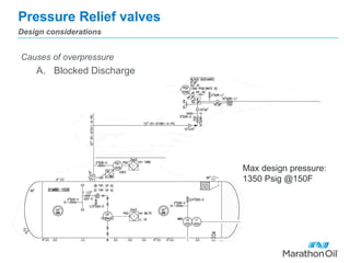
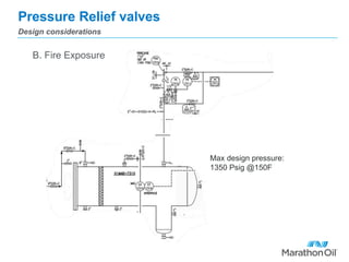
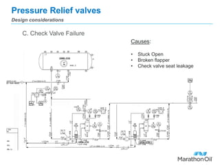
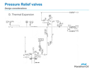
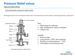
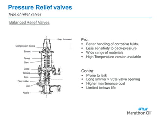
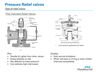


The document discusses the design and operation of pressure relief valves, emphasizing safety and compliance with ASME and API codes. It outlines various types of relief valves, their advantages and disadvantages, and considerations for sizing and installation in process systems. Additionally, it highlights overpressure scenarios, causes of malfunction, and industry practices for ensuring effective pressure relief management.


