Download as PDF, PPTX
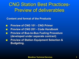
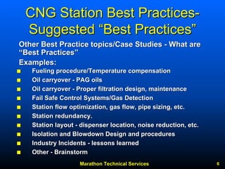
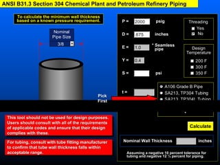
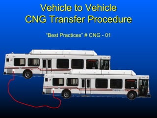
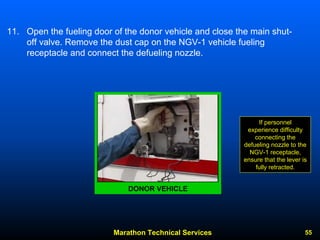
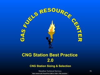
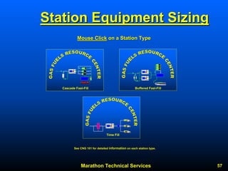

This document provides a summary of a presentation on recommended practices for compressed natural gas (CNG) fueling station design, construction, and operation. It discusses the purpose and scope of the project to compile industry best practices related to CNG stations. It also previews deliverables that will be provided on CD/web formats, including a CNG primer manual, code official's handbook, and procedures for fueling buses. Potential best practices topics are brainstormed, such as fueling procedures, filtration, control systems, station layout and redundancy.


![[DSC Europe 25] Ekaterina Bubenko - Behind the Curtain: How Data Roles Collab...](https://cdn.slidesharecdn.com/ss_thumbnails/anmv6x8dstqbbzchoklr-ekaterina-bubenko-behind-the-curtain-how-data-roles-collaborate-in-the-ai-era-a-260123083019-4b252ec7-thumbnail.jpg?width=640&height=640&fit=bounds)


![[DSC Europe 25] Josip Saban - Career building for data professionals.pptx](https://cdn.slidesharecdn.com/ss_thumbnails/zroflcttkm1vmli0txea-josip-saban-career-building-for-data-professionals-260123083019-587cdb8c-thumbnail.jpg?width=640&height=640&fit=bounds)


