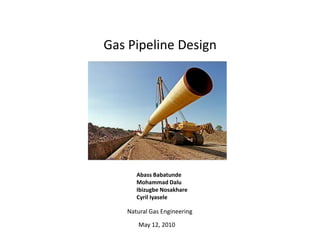
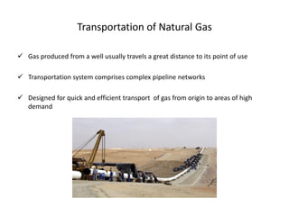
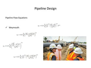
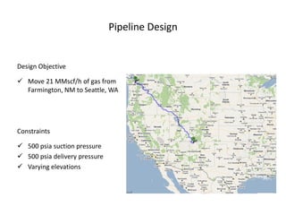
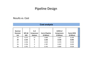
Gas Pipeline Design


      Abass Babatunde
      Mohammad Dalu
      Ibizugbe Nosakhare
      Cyril Iyasele

   Natural Gas Engineering

      May 12, 2010
Outline


 Introduction

 Natural gas gathering

 Transportation of natural gas

 Pipeline components

 Pipeline design

 Conclusion / recommendation
Introduction


The efficient and effective movement of natural gas from producing regions
to consumption regions requires an extensive and elaborate transportation
system

 Gas transmission to consumer may be divided into:
        Gathering system               Compression station
        Main trunk line                Distribution lines


 Pipelines provide an economical method of transporting fluids over great
  distances
Natural Gas Gathering

 The gathering system is made up of branches that lead into trunk lines

 Must be large enough to handle production of additional leases
Transportation of Natural Gas

 Gas produced from a well usually travels a great distance to its point of use

 Transportation system comprises complex pipeline networks

 Designed for quick and efficient transport of gas from origin to areas of high
  demand
Pipeline Components


 Pipes

 Compressor Stations

 Metering Stations

 Valves

 Control Stations & SCADA systems
Pipeline Components


PIPES

 Measure anywhere from 6 to 48 inches in diameter

 Certain component pipe sections consists of smaller diameter pipe (0.5 in)

 Consists of strong carbon steel material, to meet API standards

 Covered with a specialized coating to prevent corrosion when paced under ground
Pipeline Components

COMPRESSOR STATIONS

 Natural gas is highly pressurized as it travels through interstate lines

 To ensure the flowing gas remains pressurized, compression is required

 Compressor stations usually placed at 40 to 100 mile intervals along pipeline
Pipeline Components


METERING STATIONS

 Measures the flow of gas along pipeline

 Placed periodically along interstate gas lines

 Allows monitoring and management of gas in pipes
Pipeline Components


 VALVES

  Gateways: allow free flow or restriction of gas flow

  Interstate lines include valves along entire length

  Gas flow may be restricted if a section of pipe
   requires:
      maintenance
      replacement
Pipeline Components


CONTROL STATIONS

 Monitor and control gas in pipeline

 Collect, assimilate, and manage data received
  from compressor and metering stations

 Data received is provided by SCADA systems
  (Supervisory Control And Data Acquisition)
Pipeline Design

Pipeline Flow Equations


 Weymouth
Pipeline Design


Design Objective

 Move 21 MMscf/h of gas from
  Farmington, NM to Seattle, WA


Constraints

 500 psia suction pressure
 500 psia delivery pressure
 Varying elevations
Pipeline Design


Methodology


 Cities distances and elevations noted

 Average temperatures estimated for each city

 Initial pipe size selected
      Max yield strength, allowable working pressure for selected pipe noted


 Initial guess made for the C.R. required for the first compression station.

 Expected output pressure computed
Pipeline Design

Methodology

 Pipe length calculated and compared to the distance between the first two cities

 Iteration carried out to determine number of compressor stations required
  between Farmington and Seattle

 Simulation run for economical solution

 Installation costs determined

 Total cost, including cost of pipes noted
Pipeline Design

Methodology

 Initial pipe size changed, and the entire procedure above repeated

 Results evaluated to determine the optimum solution for the design
Pipeline Design

Results vs. Cost

                                 Cost analysis


 Nominal                # of                          CAPEX of
 Diameter   NPV @   Compressor    Cost of Pipeline   Compressors    Yearly OPEX
    (in)     10%      Stations      ($ Billion)       ($ Billion)    ($ Billion)
     16     4.575        17            1.068            2.167          0.168
     20     2.225        6             1.326            0.530          0.046
     24     2.436        4             1.624            0.370          0.028
     26     2.256        3             1.787            0.307          0.020
     30     2.291        2             2.142            0.009          0.018
Pipeline Design

Conclusion / Recommendation


A transportation network, with pipelines of 20 inches OD and 6 compression
stations will effectively deliver 21,000,000 scf/h of gas, from Farmington, NM
to Seattle, WA
Gas Pipeline Design

Gas Pipeline Design

  • 1.
    Gas Pipeline Design Abass Babatunde Mohammad Dalu Ibizugbe Nosakhare Cyril Iyasele Natural Gas Engineering May 12, 2010
  • 2.
    Outline  Introduction  Naturalgas gathering  Transportation of natural gas  Pipeline components  Pipeline design  Conclusion / recommendation
  • 3.
    Introduction The efficient andeffective movement of natural gas from producing regions to consumption regions requires an extensive and elaborate transportation system  Gas transmission to consumer may be divided into: Gathering system Compression station Main trunk line Distribution lines  Pipelines provide an economical method of transporting fluids over great distances
  • 4.
    Natural Gas Gathering The gathering system is made up of branches that lead into trunk lines  Must be large enough to handle production of additional leases
  • 5.
    Transportation of NaturalGas  Gas produced from a well usually travels a great distance to its point of use  Transportation system comprises complex pipeline networks  Designed for quick and efficient transport of gas from origin to areas of high demand
  • 6.
    Pipeline Components  Pipes Compressor Stations  Metering Stations  Valves  Control Stations & SCADA systems
  • 7.
    Pipeline Components PIPES  Measureanywhere from 6 to 48 inches in diameter  Certain component pipe sections consists of smaller diameter pipe (0.5 in)  Consists of strong carbon steel material, to meet API standards  Covered with a specialized coating to prevent corrosion when paced under ground
  • 8.
    Pipeline Components COMPRESSOR STATIONS Natural gas is highly pressurized as it travels through interstate lines  To ensure the flowing gas remains pressurized, compression is required  Compressor stations usually placed at 40 to 100 mile intervals along pipeline
  • 9.
    Pipeline Components METERING STATIONS Measures the flow of gas along pipeline  Placed periodically along interstate gas lines  Allows monitoring and management of gas in pipes
  • 10.
    Pipeline Components VALVES  Gateways: allow free flow or restriction of gas flow  Interstate lines include valves along entire length  Gas flow may be restricted if a section of pipe requires:  maintenance  replacement
  • 11.
    Pipeline Components CONTROL STATIONS Monitor and control gas in pipeline  Collect, assimilate, and manage data received from compressor and metering stations  Data received is provided by SCADA systems (Supervisory Control And Data Acquisition)
  • 12.
    Pipeline Design Pipeline FlowEquations  Weymouth
  • 13.
    Pipeline Design Design Objective Move 21 MMscf/h of gas from Farmington, NM to Seattle, WA Constraints  500 psia suction pressure  500 psia delivery pressure  Varying elevations
  • 14.
    Pipeline Design Methodology  Citiesdistances and elevations noted  Average temperatures estimated for each city  Initial pipe size selected  Max yield strength, allowable working pressure for selected pipe noted  Initial guess made for the C.R. required for the first compression station.  Expected output pressure computed
  • 15.
    Pipeline Design Methodology  Pipelength calculated and compared to the distance between the first two cities  Iteration carried out to determine number of compressor stations required between Farmington and Seattle  Simulation run for economical solution  Installation costs determined  Total cost, including cost of pipes noted
  • 16.
    Pipeline Design Methodology  Initialpipe size changed, and the entire procedure above repeated  Results evaluated to determine the optimum solution for the design
  • 17.
    Pipeline Design Results vs.Cost Cost analysis Nominal # of CAPEX of Diameter NPV @ Compressor Cost of Pipeline Compressors Yearly OPEX (in) 10% Stations ($ Billion) ($ Billion) ($ Billion) 16 4.575 17 1.068 2.167 0.168 20 2.225 6 1.326 0.530 0.046 24 2.436 4 1.624 0.370 0.028 26 2.256 3 1.787 0.307 0.020 30 2.291 2 2.142 0.009 0.018
  • 18.
    Pipeline Design Conclusion /Recommendation A transportation network, with pipelines of 20 inches OD and 6 compression stations will effectively deliver 21,000,000 scf/h of gas, from Farmington, NM to Seattle, WA