Downloaded 478 times


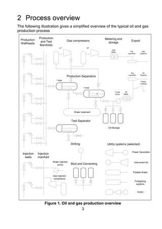

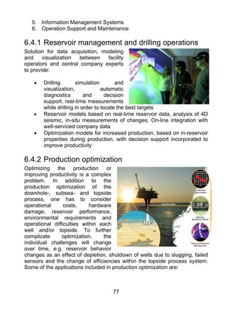


This document provides an overview of oil and gas production processes. It begins with a brief history of oil drilling and uses. Section 2 provides a high-level process overview showing the key stages from wellheads through separation, compression, storage and export. The main stages include manifolds and gathering, separation, gas treatment and compression, and metering and export. Supporting utility systems are also outlined.


