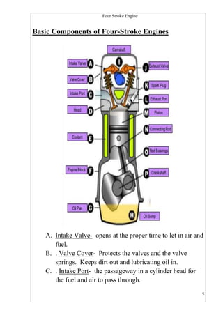
The document provides an overview of four-stroke engines, including:
- The four strokes that make up the combustion cycle: intake, compression, power/ignition, and exhaust.
- Key components of four-stroke engines like the intake/exhaust valves, piston, crankshaft, and spark plug.
- The basic operation of a four-stroke petrol/gasoline engine, which draws in an air-fuel mixture, compresses it, ignites it with a spark plug, and exhausts the gases.
this is the ppt on 2 stroke and 4 stroke petrol engine. . i made this ppt with the help of dhrumil patel .who is in the L.D. college of engineering in chemical department. . i am very thankful to him for being my great partner. . .thanx dhrumil..
Bike Engines-Two Stroke/Four Stroke Engines ClassificationBike Jinni
BikeJinni - Bike Engines Classification. Two Stroke/Four Stroke Engines. Engine technical terms. Type of design in Bike Engines. Engine Cooling Systems, spark plug, Working of bike engines.
Bike Engines-Two Stroke/Four Stroke Engines ClassificationBike Jinni
BikeJinni - Bike Engines Classification. Two Stroke/Four Stroke Engines. Engine technical terms. Type of design in Bike Engines. Engine Cooling Systems, spark plug, Working of bike engines.
Australian Stockmarket Scan - Automobile and Components SectorShare Trading
Automobile and Components Sector - Australian Sharemarket Scan - Quickly browse through the charts to detect patterns and trends. Great for Technical analysis. Charts shown display 100 MA + 50 EMA and a Custom MACD signal.
DESIGN AND ANALYSIS OF HEAVY VEHICLE CHASSIS USING HONEY COMB STRUCTUREIjripublishers Ijri
Automotive chassis is a skeletal frame on which various mechanical parts like engine, tires, axle assemblies, brakes,
steering etc. are bolted. The chassis is considered to be the most significant component of an automobile. It is the most
crucial element that gives strength and stability to the vehicle under different conditions.
This thesis deals with the design optimization and material suggestion for heavy vehicle chassis (container vehicle).
In the first step literature survey will be conducted for further processes (for the selection of material and geometric
selection).
In the next step modeling will be done to carry out the analysis. Structural Analysis will be conducted using traditional
material M.S; Composite materials FRP (E-glass)& Carbon epoxy (S-2 glass), also analysis will be conducted on present
and updated models.
In the next step impact test and fatigue analysis will be conducted on same to find impact and fatigue characteristics.
Objective: By doing this project chassis manufacturing company can save time & efforts because of easy manufacturing
method. End user can save money on chassis purchase and savings on reduced fuel consumption due to low weight of
chassis with composites
History Engine 2.0: Researching Locally, Collaborating GloballyNITLE
Robert Nelson, Director, Digital Scholarship Lab, University of Richmond, and Christine Berkowitz, Lecturer, University of Toronto Scarborough
The History Engine is a pedagogically oriented project that collects “episodes”—concise vignettes about local historical events—written by undergraduate students. This presentation will highlight how this project uses digital technologies to foster collaboration among students within and between different universities, fosters inter-institutional collaboration among the many colleges that have participated in the project, and publishes student scholarship that is of interest and value to a broad public.
This slide show accompanies the learner guide "Mechanical Technology Grade 10" by Charles Goodwin, Andre Lategan & Daniel Meyer, published by Future Managers Pty Ltd. For more information visit our website www.futuremanagers.net
A presentation on 4 stroke spark ignition engine
Content of this presentation are as follows -
What is I.C. Engine?
Basic parts of I.C. Engine
Working of 4-stroke Engine
1) Suction stroke
2) Compression stroke
3) Expansion stroke
4) Exhaust stroke
Advantages
Disadvantages
Thank You
This is Mechanical project report on Fabrication of an Active Air Suspension System. Air ride suspension
carries the load on each axle with a pressurized air bag just as a high pressure balloon. This system provides
the smoothest and most shock free ride of any of the known vehicle suspension system. An air suspension
includes a multiple air spring assemblies that each includes a piston airbag and a primary airbag mounted over
the piston airbag. The main and piston air bags each have a variable volume that is controlled independently
of the other for active suspension control.
Front Wheel Steering System With Moveable HeadlightsSuchit Moon
This is Mechanical project report on Front wheel steering system with moveable headlights with latest
electronics technology. The most standard steering arrangement is to show the front wheels employing
a hand–operated handwheel that is positioned before of the motive force, via the steering column, which
can contain universal joints to permit it to deviate somewhat from a line. alternative arrangements ar
generally found on differing types of vehicles, as an example, a tiller or rear–wheel steering. tracked
vehicles like tanks sometimes use differential steering — that's, the tracks are created to maneuver
at completely different speeds or maybe in opposite directions to originate a amendment in fact.
Renewable energy is generally electricity supplied from sources, such as wind power, solar power,
geothermal energy, hydro power and various forms of biomass. The popularity of renewable energy
has experienced a significant upsurge in recent times due to the exhaustion of conventional power
generation methods and increasing realization of its adverse effects on the environment. Wind energy
has been harnessed for centuries but it has only emerged as a major part of our energy solution quite
recently and this report focus on utilizing wind energy by using vertical axis wind turbine.
GridMate - End to end testing is a critical piece to ensure quality and avoid...ThomasParaiso2
End to end testing is a critical piece to ensure quality and avoid regressions. In this session, we share our journey building an E2E testing pipeline for GridMate components (LWC and Aura) using Cypress, JSForce, FakerJS…
Alt. GDG Cloud Southlake #33: Boule & Rebala: Effective AppSec in SDLC using ...James Anderson
Effective Application Security in Software Delivery lifecycle using Deployment Firewall and DBOM
The modern software delivery process (or the CI/CD process) includes many tools, distributed teams, open-source code, and cloud platforms. Constant focus on speed to release software to market, along with the traditional slow and manual security checks has caused gaps in continuous security as an important piece in the software supply chain. Today organizations feel more susceptible to external and internal cyber threats due to the vast attack surface in their applications supply chain and the lack of end-to-end governance and risk management.
The software team must secure its software delivery process to avoid vulnerability and security breaches. This needs to be achieved with existing tool chains and without extensive rework of the delivery processes. This talk will present strategies and techniques for providing visibility into the true risk of the existing vulnerabilities, preventing the introduction of security issues in the software, resolving vulnerabilities in production environments quickly, and capturing the deployment bill of materials (DBOM).
Speakers:
Bob Boule
Robert Boule is a technology enthusiast with PASSION for technology and making things work along with a knack for helping others understand how things work. He comes with around 20 years of solution engineering experience in application security, software continuous delivery, and SaaS platforms. He is known for his dynamic presentations in CI/CD and application security integrated in software delivery lifecycle.
Gopinath Rebala
Gopinath Rebala is the CTO of OpsMx, where he has overall responsibility for the machine learning and data processing architectures for Secure Software Delivery. Gopi also has a strong connection with our customers, leading design and architecture for strategic implementations. Gopi is a frequent speaker and well-known leader in continuous delivery and integrating security into software delivery.
UiPath Test Automation using UiPath Test Suite series, part 6DianaGray10
Welcome to UiPath Test Automation using UiPath Test Suite series part 6. In this session, we will cover Test Automation with generative AI and Open AI.
UiPath Test Automation with generative AI and Open AI webinar offers an in-depth exploration of leveraging cutting-edge technologies for test automation within the UiPath platform. Attendees will delve into the integration of generative AI, a test automation solution, with Open AI advanced natural language processing capabilities.
Throughout the session, participants will discover how this synergy empowers testers to automate repetitive tasks, enhance testing accuracy, and expedite the software testing life cycle. Topics covered include the seamless integration process, practical use cases, and the benefits of harnessing AI-driven automation for UiPath testing initiatives. By attending this webinar, testers, and automation professionals can gain valuable insights into harnessing the power of AI to optimize their test automation workflows within the UiPath ecosystem, ultimately driving efficiency and quality in software development processes.
What will you get from this session?
1. Insights into integrating generative AI.
2. Understanding how this integration enhances test automation within the UiPath platform
3. Practical demonstrations
4. Exploration of real-world use cases illustrating the benefits of AI-driven test automation for UiPath
Topics covered:
What is generative AI
Test Automation with generative AI and Open AI.
UiPath integration with generative AI
Speaker:
Deepak Rai, Automation Practice Lead, Boundaryless Group and UiPath MVP
GraphRAG is All You need? LLM & Knowledge GraphGuy Korland
Guy Korland, CEO and Co-founder of FalkorDB, will review two articles on the integration of language models with knowledge graphs.
1. Unifying Large Language Models and Knowledge Graphs: A Roadmap.
https://arxiv.org/abs/2306.08302
2. Microsoft Research's GraphRAG paper and a review paper on various uses of knowledge graphs:
https://www.microsoft.com/en-us/research/blog/graphrag-unlocking-llm-discovery-on-narrative-private-data/
The Art of the Pitch: WordPress Relationships and SalesLaura Byrne
Clients don’t know what they don’t know. What web solutions are right for them? How does WordPress come into the picture? How do you make sure you understand scope and timeline? What do you do if sometime changes?
All these questions and more will be explored as we talk about matching clients’ needs with what your agency offers without pulling teeth or pulling your hair out. Practical tips, and strategies for successful relationship building that leads to closing the deal.
Dr. Sean Tan, Head of Data Science, Changi Airport Group
Discover how Changi Airport Group (CAG) leverages graph technologies and generative AI to revolutionize their search capabilities. This session delves into the unique search needs of CAG’s diverse passengers and customers, showcasing how graph data structures enhance the accuracy and relevance of AI-generated search results, mitigating the risk of “hallucinations” and improving the overall customer journey.
Unlocking Productivity: Leveraging the Potential of Copilot in Microsoft 365, a presentation by Christoforos Vlachos, Senior Solutions Manager – Modern Workplace, Uni Systems
Observability Concepts EVERY Developer Should Know -- DeveloperWeek Europe.pdfPaige Cruz
Monitoring and observability aren’t traditionally found in software curriculums and many of us cobble this knowledge together from whatever vendor or ecosystem we were first introduced to and whatever is a part of your current company’s observability stack.
While the dev and ops silo continues to crumble….many organizations still relegate monitoring & observability as the purview of ops, infra and SRE teams. This is a mistake - achieving a highly observable system requires collaboration up and down the stack.
I, a former op, would like to extend an invitation to all application developers to join the observability party will share these foundational concepts to build on:
In the rapidly evolving landscape of technologies, XML continues to play a vital role in structuring, storing, and transporting data across diverse systems. The recent advancements in artificial intelligence (AI) present new methodologies for enhancing XML development workflows, introducing efficiency, automation, and intelligent capabilities. This presentation will outline the scope and perspective of utilizing AI in XML development. The potential benefits and the possible pitfalls will be highlighted, providing a balanced view of the subject.
We will explore the capabilities of AI in understanding XML markup languages and autonomously creating structured XML content. Additionally, we will examine the capacity of AI to enrich plain text with appropriate XML markup. Practical examples and methodological guidelines will be provided to elucidate how AI can be effectively prompted to interpret and generate accurate XML markup.
Further emphasis will be placed on the role of AI in developing XSLT, or schemas such as XSD and Schematron. We will address the techniques and strategies adopted to create prompts for generating code, explaining code, or refactoring the code, and the results achieved.
The discussion will extend to how AI can be used to transform XML content. In particular, the focus will be on the use of AI XPath extension functions in XSLT, Schematron, Schematron Quick Fixes, or for XML content refactoring.
The presentation aims to deliver a comprehensive overview of AI usage in XML development, providing attendees with the necessary knowledge to make informed decisions. Whether you’re at the early stages of adopting AI or considering integrating it in advanced XML development, this presentation will cover all levels of expertise.
By highlighting the potential advantages and challenges of integrating AI with XML development tools and languages, the presentation seeks to inspire thoughtful conversation around the future of XML development. We’ll not only delve into the technical aspects of AI-powered XML development but also discuss practical implications and possible future directions.
A tale of scale & speed: How the US Navy is enabling software delivery from l...sonjaschweigert1
Rapid and secure feature delivery is a goal across every application team and every branch of the DoD. The Navy’s DevSecOps platform, Party Barge, has achieved:
- Reduction in onboarding time from 5 weeks to 1 day
- Improved developer experience and productivity through actionable findings and reduction of false positives
- Maintenance of superior security standards and inherent policy enforcement with Authorization to Operate (ATO)
Development teams can ship efficiently and ensure applications are cyber ready for Navy Authorizing Officials (AOs). In this webinar, Sigma Defense and Anchore will give attendees a look behind the scenes and demo secure pipeline automation and security artifacts that speed up application ATO and time to production.
We will cover:
- How to remove silos in DevSecOps
- How to build efficient development pipeline roles and component templates
- How to deliver security artifacts that matter for ATO’s (SBOMs, vulnerability reports, and policy evidence)
- How to streamline operations with automated policy checks on container images
How to Get CNIC Information System with Paksim Ga.pptxdanishmna97
Pakdata Cf is a groundbreaking system designed to streamline and facilitate access to CNIC information. This innovative platform leverages advanced technology to provide users with efficient and secure access to their CNIC details.
DevOps and Testing slides at DASA ConnectKari Kakkonen
My and Rik Marselis slides at 30.5.2024 DASA Connect conference. We discuss about what is testing, then what is agile testing and finally what is Testing in DevOps. Finally we had lovely workshop with the participants trying to find out different ways to think about quality and testing in different parts of the DevOps infinity loop.
GraphSummit Singapore | The Art of the Possible with Graph - Q2 2024Neo4j
Neha Bajwa, Vice President of Product Marketing, Neo4j
Join us as we explore breakthrough innovations enabled by interconnected data and AI. Discover firsthand how organizations use relationships in data to uncover contextual insights and solve our most pressing challenges – from optimizing supply chains, detecting fraud, and improving customer experiences to accelerating drug discoveries.
2. Four Stroke Engine
History of the Four-Stroke
Automobile Engine
Perhaps the most well known engine type in the world, the automotive fourstroke engine has become the power plant of choice for today's consumers
due to itsgreater efficiency and cost effectiveness over alternate
reciprocating engines.The story of the internal combustion engine began in
1680 with a Dutch physi-cist, Christian Huygens, who conceptually
designed an engine fueled by gun powder. However, the first internal
combustion engine was actually built by a Sweetish
inventor by the name of Francios Isaac de Rivaz in 1807. Through the
combustionof a hydrogen and oxygen mixture, his engine, with some
difficulty, powered acrudely constructed automobile. As the years went on,
other inventors modified the design to be fueled by anything from gasoline
to coal. The next greatest leap came in 1862 when a French engineer,
Alphonse Beau de Rochas, designed and patented the first four-stroke
engine. In 1864 an Austrian engineer, Siegfried Marcus, build the first gasoline powered vehicle, which was comprised of a cart
and a one cylinder engine. But the biggest break through came in 1876
when Nikolaus August Otto invented the first successful four-stroke engine,
aptly nick-namingthe four-stroke cycle the ”Otto Cycle.” [1] The next great
milestone in the development of the four stroke engine was achieved by
Gottlieb Daimler in 1885, who invented an engine with a vertical positioned
cylinder, fueled by gasoline injected into a cylinder chamber through a
carburetor. The innovations from these important inventors over the years
culminated in Daimler's engine which is commonly referred to as the ”blue
print” to the modern day internal combustion engine. [1] From the inception
of the four-stroke internal combustion engine, many paths have been
explored and followed to create the superior design, especially in the
configuration of the cylinders. In general, there are seven types of
reciprocating engine designs, an engine that employs one or more cylinders
in which a piston(s) reciprocates back and forth. The first of these designs
was the single cylinder engine. After its success, designers began to play
with twin engines, or two cylinder engines which lead to the In-Line
Engine, the V Engine, the Opposed Cylinder Engine, the W engine, the
Opposed Piston Engine, and the Radial Engine. These different setups
where further explored with engines such as the Vauxhall Wyvern and
Velox engines to the Ford V-Four engine, utilizing an even greater numbers
of cylinders than the original twin engines.
2
3. Four Stroke Engine
Today's four-stroke engine manufacturer's mainly build In-Line or V
configured engines. Perhaps the most widely recognized engine today is the
Chevrolet Small Block V8 Engine. This engine was made popular through
their depend ability and through hobbyists and the performance market
because of the inter changeability of parts. After 35 years, General Motors
discontinued their infamous engine, replacing it with the new Generation II
engine in 1992. Although Chevroletseemingly has dominated today's after
market industry, other manufacturers have successfully made engines for
their vehicles from the Ford V-Eight, to the Cadillac North Star, to the
Porsche In-Line Six as well as mainly others.
3
5. Four Stroke Engine
Basic Components of Four-Stroke Engines
A. Intake Valve- opens at the proper time to let in air and
fuel.
B. . Valve Cover- Protects the valves and the valve
springs. Keeps dirt out and lubricating oil in.
C. . Intake Port- the passageway in a cylinder head for
the fuel and air to pass through.
5
6. Four Stroke Engine
D. Head- a platform containing most of the parts of the
combustion chamber.
E. Coolant- circulating water and antifreeze to keep the
temperature regulated.
F. . Engine Block- cast in one piece. The basis for most
of the parts of the engine.
G. Oil Pan- where the oil is collected and recirculated.
H. Oil Sump- the collected oil primarily for lubricating
the crankshaft and rod bearing
I. Camshaft- a round shaft with lobes, that rotates to
open and close the fuel and exhaust valves.
J. . Exhaust Valve- open at the proper time to release the
exhaust
K. Spark Plug- a device, inserted into the combustion
chamber for firing an electrical spark to ignite air-fuel
mixture
L. Exhaust Port- the passageway in a cylinder head, for
the exhaust to pass through
M. . Piston- the part of the engine that moves up and
down in the cylinder converting the gasoline into
motion
N. Connecting Rod- links the piston to the crankshaft.
O. Rod Bearing- used to reduce friction to the rod and
crankshaft
P. Crankshaft- converts the up and down motion of the
piston into a turning, or rotating motion
6
8. Four Stroke Engine
Engine-Operating Cycle of Most Petrol and Diesel
Engines
Each movement of the cylinder up or down the cylinder is one stroke of
the four stroke combustion cycle or Otto cycle. Most modern internal
combustion engines use the four stroke cycle. The four
stroke cycle consists of an induction stroke where air and fuel are taken
into the cylinder as the piston moves downwards, a compression stroke
where the air and fuel are compressed by the upstroke of the cylinder, the
ignition or power stroke where the compressed mixture is ignited and the
expansion forces the cylinder downwards, and an exhaust stroke where the
waste gases are forced out of the
cylinder. The intake and outlet ports open and close to allow air to be drawn
into the cylinder and exhaust gases to be expelled.
During the intake stroke the inlet valve opens at the top of the cylinder, as
the piston moves down air and fuel are drawn into the cylinder. As the
piston reaches its lowest position the inlet valve closes and the piston
travels upwards compressing the air -fuel mixture. As the pi ston reaches its
highest position
at maximum compression a spark ignites the mixture causing a rapid
expansion of gas raising the pressure in the cylinder and forcing the piston
downwards. Once the cylinder has reached its lowest position the outlet
port o pens and as the piston rises up the cylinder the exhaust gases are
forced out. The valves which open and close the port are sprung to make
them naturally close. The valves are opened by a system of rotating cams
and pushrods driven by a camshaft which in t urn is timed and driven from
the crankshaft. The valve timings vary between engines depending on the
setup, generally there is some overlap to speed the flow of gases
8
10. Four Stroke Engine
Intake
The intake stroke of the combustion cycle is when
the piston travels down the cylinder with the intake port/ports open. A
mixture of air and explosive fuel are drawn into the cylinder, the
proportions of which are called the air -fuel ratio. Both the air-fuel ratio and
the quality of the mixture (dispersion, droplet size etc.) is i mportant for an
efficient combustion process. There are two methods of mixing air and fuel
in a combustion engine, using a carburettor or fuel injection system.
In a carburetted engine, during the intake stroke of the piston a vacuum is
created in the inlet manifold. With a multi cylinder engine the vacuum is
almost constant. The carburettor is located at the top of the manifold and air
is drawn through it by the vacuum created in the manifold. The carburettor
has a small fuel chamber supplied from the fuel tank by a pump, fuel passes
through the carburettor to small fuel jets positioned in the air flow. The flow
of air past the jets creates a pressure difference causing the fuel to be drawn
out. The fuel vaporises in the air flow and passes through the manifold and
into cylinders on their intake stroke. The diagram below shows the basic
operation of a fixed jet carburettor.
Electronic fuel injection systems spray fuel at high pressure either directly
into the combustion chamber or into the intake port of the cylinder during
the intake stroke. Using fuel injection enables improved control over the air
-fuel mixture and reduces the power required to draw fuel from the jets. The
diagram below shows a typical electronic fuel injection system. Diesel
engines typically use direct injection which injects fuel directly into the
combustion chamber during the compression stroke. The intake stroke on a
diesel engine only draws air into the cylinder.
10
13. Four Stroke Engine
The compression stroke is the upwards movement of the piston in the
cylinder with the valves closed following the intake stroke. This upwards
motion compresses the fuel air mixture inside the combustion chamber
raising the pressure. The difference between the initial volume of the
cylinder and the final volume at the top of the compression stroke is known
as the compression ratio. Typically this is approximately 9:1 in spark
ignition engines and 15:1 for diesel engines. The compression ratio is
particularly important in compression fired engines such as diesel engines.
The fuel - air mix and compression ratio is critical to avoid pre -ignition
which is the abnormal ignition of fuel in the combustion chamber before the
combustion stroke. In diesel engines the fuel is injected under high pressure
towards the top of the compression stroke. The distribution of fuel before
combustion is also of interest because it affects the efficiency of
combustion.
13
15. Four Stroke Engine
Combustion
Spark plugs are used to generate the spark which ignites the compressed
fuel and air mixtu re in the spark ignition engine. To generate the spark a
high voltage of around 20,000 Volts is applied. Low voltage current is fed
through the primary winding of an inductor coil generating a magnetic field.
The high voltage is generated when the low volt age supply is interrupted
and the magnetic field breaks down generating a high voltage in the
secondary winding which has a much larger number of coils. The low
voltage supply to the coil is controlled by the distributor which also controls
the spark plug that the high voltage surge is sent to. The distributor timing
is critical and usually is timed mechanically from the engine. The diagram
below shows the typical set - up of an ignition system for a spark ignition
engine. Compression ignition engines such as the diesel engine do not use
spark plugs to ignite the fuel - air mix. When the piston reaches the top of
the compression stroke the temperature and pressure in the combustion
chamber is sufficient to ignite the mixture. Controlled ignition in both spark
ignition and diesel engines is essential for efficient combustion and avoid
uncontrolled combustion effects such as pre- ignition, auto - ignition and
engine knock.
15
17. Four Stroke Engine
Exhaust
Exhaust gases are pushed out of the cylinder by the
upwards motion of the piston following the ignition stroke. The exhaust
gases are passed into the exhaust manifold and channelled into the exhaust
pipe where they are released into the atmosphere. The exhaust system may
contain a smoke box to trap the larger soot particles, it may also be fitted
with a catalytic converter which removes some of the harmful components
from the exhaust gases. On newer cars some of the exhaust gases are
recycled back into the inlet system (typically at the manifold or air filter),
this is known as exhaust gas re - circulation EGR. The efficiency of the
combustion process and the design of the engine determine the exhaust
constituents. Typically exhaust gases contain oxygen, nitrogen, water
vapour, carbon dioxide, carbon monoxide, hydrogen, nitrous oxides,
particulates and unburned hydrocarbons.
17
19. Four Stroke Engine
Exhaust and Inlet Valve Overlap
Exhaust and inlet valve overlap is the transition
between the exhaust and inlet strokes and is a practical necessity for the
efficient running of any internal combustion engine. Given the constraints
imposed by the operation of mechanical valves and the inertia of the air in
the inlet manifold, it is necessary to begin opening the inlet valve before the
piston reaches Top Dead Centre (TDC) on the exhaust stroke. Likewise, in
order to effectively remove all of the combustion gases, the exhaust valve
remains open until after TDC. Thus, there is a point in each full cycle when
both exhaust and inlet valves are open. The number of degrees over which
this occurs and the proportional split across TDC is very much dependent
on the engine design and the speed at which it operates.
19
21. Four Stroke Engine
The cycle of operation in a four stroke petrol engine is completed
in two revolutions of crank shaft or four strokes of piston. Stroke is
defined as the distance traveled by the piston from one of the dead
centers to the other dead centre. It is also equal to two times the crank
radius. Hence in a four stroke engine work is obtained only during one
stroke out of the four strokes of the piston required to complete one
cycle. This engine works on Otto or constant volume cycle. 1. Suction
stroke: To start with the piston is at or very near T.D.C. and the inlet valve
is open and exhaust valve is closed. As the piston moves from
T.D.C. to B.D.C. rarefaction is formed in the cylinder which causes
the charge to rush in and fill the space vacated by the piston. The
charge consists of a mixture of air and petrol prepared by the
carburetor. The admission of charge inside the engine cylinder
continues until the inlet valve closes at B.D.C. 2. Compression stroke: Both
the valves are closed and the piston moves from B.D.C. to T.D.C. The
charge is compressed up to a compression ratio of 5:1 to 9:1 and pressure
and temperature at the end of compression are about 6 to 12 bar and 250º C
to 300º C respectively. 3. Working, Power or Expansion stroke: When
the piston reaches T.D.C. position, or just at the end of compression
stroke, the charge is ignited by causing an electric spark between the
electrodes of a spark plug, which is located some where in the walls
of cylinder head. During combustion the chemical energy of fuel is released
and there is rise in temperature and pressure of gases. The temperature of
gases increases to about 1800º C to 2000º C and the pressure reaches 30 to
40 bar. Up till now the volume of gases formed however remains almost
constant with both valves closed. Now the combustion products expand
and push the piston down the cylinder. The reciprocating piston motion is
converted into rotary motion of crankshaft by a connecting rod and crank.
During expansion the pressure drops due to increase in the volume of gases
and absorption of heat by cylinder walls. 4. Exhaust stroke: Theoretically
exhaust valve opens at the end of working stroke when the piston is at
B.D.C. position. But actually exhaust valve begins to open when about 85
% of the working stroke is completed. A pressure of 4 to 5 bar at this instant
forces about 60 % of the burnt gases into the exhaust manifold at high
21
22. Four Stroke Engine
speed. The remaining burnt gases are cleared off the swept volume when
the piston moves from B.D.C. to T.D.C. During this stroke the pressure
in side the cylinder is slightly above the atmospheric value. Some of
the burnt gases are however left in the clearance space. The exhaust
valve closes shortly after the piston reaches T.D.C. The inlet valve opens
slightly before the end of exhaust stroke and the cycle repeats.
Four Stroke Engine
22
25. Four Stroke Engine
The cycle of operation in a four stroke diesel engine is completed in two
revolutions of crankshaft or four strokes of piston using diesel oil as fuel.
This engine works on diesel cycle. 1. Suction Stroke: Starting of engine
is done by an electric motor or manually. In both cases the energy is
supplied to the engine. In this stroke the inlet valve opens and the outlet
valve remains closed. Piston moves from T.D.C. to B.D.C. and in
this way a vacuum is created in the cylinder. This vacuum is filled
by air alone and piston reaches to B.D.C. 2. Compression Stroke: Both
valves are closed. This time piston moves from B.D.C. to T.D.C. Air is
compressed in this stroke up to a compression ratio of 15:1 to 22:1 and a
very high temperature is produced due to high pressure. The high
temperature is the only cause of combustion of the fuel. The piston takes the
power in this stroke from the flywheel. During this stroke the pressure and
temperature attain a high value of 40 to 60 bar and 600º C to 700º C. 3.
Working Stroke: At the end of compression stroke or when the
piston reaches the T.D.C. position, a fine spray of diesel is injected in the
cylinder through injector. The fuel burns by the heat of compressed air and
due to its burning the power is produced. This power pushes the piston
downward i.e. from T.D.C. to B.D.C. The excess energy of the piston is
stored in the flywheel of the engine, which is further used for the
remaining three strokes of the engine. The reciprocating motion of the
piston is converted into the rotary motion of the crankshaft by
connecting rod and crank. During expansion the pressure drops due to
increase in volume of gases and absorption of heat by cylinder walls. 4.
Exhaust Stroke: The exhaust valve begins to open when about 85%
of the working stroke is completed. The force of piston coming from
B.D.C. to T.D.C. forces the burnt gases into the exhaust manifold. Some
of the gases are forced out due to higher pressure in the cylinder and the
remaining gases are forced out by the piston. Some of the burnt gases are
however left inside the clearance space. The exhaust valve closes shortly
after T.D.C. The inlet valve opens slightly before the end of exhaust
and in this way the cycle repeats.
25