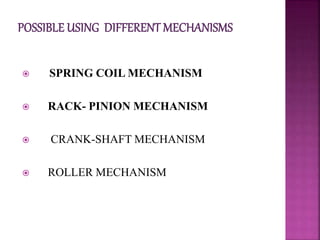
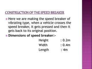
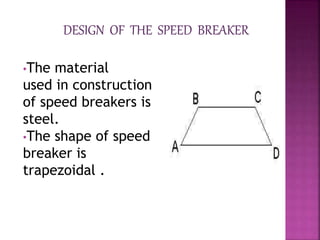
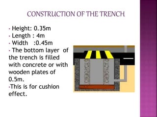
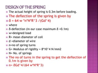
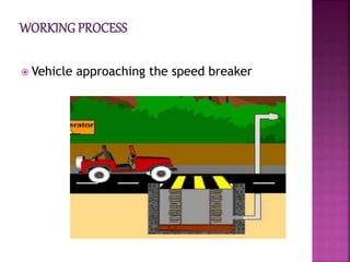
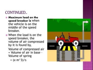
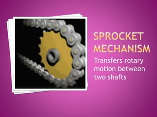
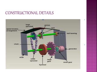
PREPARED BY-
JASHOBANTI BISWAL
REGDN. NO-0901106119
ELECTRICAL ENGINEEERING DEPARTMENT
 Introduction
 Different mechanisms
 Spring coil mechanism
 Rack pinion mechanism
 MERITS and demerit
 scope and uses
 CONCLUSION
A large amount of energy is wasted
at the speed breakers through
friction , every time a vehicle passes
over it.
So electricity can be generated using
the vehicle weight (potential energy)
as input.
So, this is a small step to try to
improve this situation.
 SPRING COIL MECHANISM
 RACK- PINION MECHANISM
 CRANK-SHAFT MECHANISM
 ROLLER MECHANISM
 OUT OF THE ABOVE METHODS
CRANK-SHAFT MECHANISM & ROLLER
MECHANISM ARE NOT USED BECAUSE OF
THE DEMERITS RELATED TO THESE METHODS.
 SO ONLY SPRING COIL MECHANISM &
RACK- PINION MECHANISM ARE
DISCUSSED.
Working principle
Conversion of mechanical
energy to pneumatic energy
which is converted to
electical energy
 Here we are making the speed breaker of
vibrating type, when a vehicle crosses the
speed breaker, it gets pressed and then it
gets back to its original position.
 Dimensions of speed breaker:-
Height : 0.2m
Width : 0.4m
Length : 4m
•The material
used in construction
of speed breakers is
steel.
•The shape of speed
breaker is
trapezoidal .
• Height: 0.35m
• Length : 4m
• Width :0.45m
• The bottom layer of
the trench is filled
with concrete or with
wooden plates of
0.5m.
•This is for cushion
effect.
 The actual height of spring is 0.3m before loading.
 The deflection of the spring is given by
 δ = 64 w *n*N*R^3 /(Gd^4)
 where
 δ-deflection (in our case maximum δ =0.1m)
 w=designed load
 R= mean diameter of coil
 d =diameter of wire
 n=no of spring turns
 G= Modulus of rigidity = 8*10^4 N/mm2
 N= No. of springs
 The no of turns in the spring to get the deflection of
0.1m is given by
 n= δGd^4/(64 w*N*R^3)
 Vehicle approaching the speed breaker
 Maximum load on the
speed breaker is when
the vehicle is on the
middle of the speed
breaker.
 When the load is on the
speed breaker, the
volume of air compressed
by it is found by,
Volume of compressed air
= Volume of air in base –
Volume of spring
= (x m^3)/s
 When the pressure
in the FRL unit
exceeds the
defined level the
valve opens and
the pressurized air
is given to the
nozzle.
 The diameter of the inlet
of nozzle must be greater
than outlet.
 Here the pressure energy
is converted to kinetic
energy i.e pressure→high
velocity.
 This high velocity
compressd air when hits
the impeller ,makes it to
rotate.
CONSISTS -
 Casing
 Runner and buckets
CASING-
 This is provided to safeguard device against
accidents.
 It consists of a
circular disc on the
periphery of which
have number of
buckets evenly spaced
are fixed. Each bucket
is divided in to 2
symmetrical parts by
a dividing wall is know
as splitter.
 When the air strikes
the runner ,it rotates
& continues rotation
due to inertia.
 An electrical generator is a machine which
converts mechanical energy in to electrical
energy.
 The output of the alternator is used to light
the street lights & is rectified & stored in
batteries.
PRINCIPLE
MECHANICAL ENERGY IS
CONVERTED TO ELECTRICAL
ENERGY
 The various machine elements used in the
construction of power hump are
 RACK-PINION
 SPROCKETS
 GEARS
 FLY WHEEL
 SHAFT
 ELECTRIC GENERATOR
Transfers rotary
motion between
two shafts
The input gear
transfers power
to the output
gear.
This is used to regulate the energy and
maintain the energy at an uniform
level so that the shaft rotate at an
uniform r.p.m
 Here the reciprocating motion of the speed-
breaker is converted into rotary motion using
the rack and pinion arrangement.
 Rack and pinion gears normally change rotary
motion into linear motion, but sometimes we
use them to change linear motion into rotary
motion.
 The axis of the pinion is coupled with the sprocket
arrangement.
 The axis of the smaller sprocket is coupled to a
gear arrangement.
 Finally the gear arrangement is coupled with the
generator
Speed of vehicle
(kmhr)
Voltage generated
(volts)
 10
 20
 30
 40
 50
 7.93
 6.28
 5.03
 4.66
 3.03
Load(kgs) Voltage generated(V)
 60(man load)
 130
 170
 200
 270
 8.33
 9.45
 10.22
 11.23
 11.81
merits demerits
 Low Budget electricity
production
 Less floor area
 No obstruction to traffic
 Suitable at parking of
multiplexes, malls, toll
booths, signals, etc.
 We have to check
mechanism from time to
time
 It can get rusted in rainy
season
 May not work with light
weight vehicles
 Less quantity
 This mechanism is very economical and easy
to install.
 Two protocols of this type of speed breakers
are developed in India .not practically
implemented till date.
 Practically implemented in New Jersy,China
and Indonesia.
 Lots of researches and investgations are
going on to practically utilise this technique
.
 The existing source of energy such as coal, oil etc
may not be adequate to meet the ever increasing
energy demands. These conventional sources of
energy are also depleting and may be exhausted.
 These are some non-conventional methods of
producing energy. This project is a one step to path
of exploring the possibilities of energy from
several non-conventional energy sources.
THANK YOU

Power generation from speedbreakers

  • 1.
    PREPARED BY- JASHOBANTI BISWAL REGDN.NO-0901106119 ELECTRICAL ENGINEEERING DEPARTMENT
  • 2.
     Introduction  Differentmechanisms  Spring coil mechanism  Rack pinion mechanism  MERITS and demerit  scope and uses  CONCLUSION
  • 3.
    A large amountof energy is wasted at the speed breakers through friction , every time a vehicle passes over it. So electricity can be generated using the vehicle weight (potential energy) as input. So, this is a small step to try to improve this situation.
  • 4.
     SPRING COILMECHANISM  RACK- PINION MECHANISM  CRANK-SHAFT MECHANISM  ROLLER MECHANISM
  • 5.
     OUT OFTHE ABOVE METHODS CRANK-SHAFT MECHANISM & ROLLER MECHANISM ARE NOT USED BECAUSE OF THE DEMERITS RELATED TO THESE METHODS.  SO ONLY SPRING COIL MECHANISM & RACK- PINION MECHANISM ARE DISCUSSED.
  • 6.
    Working principle Conversion ofmechanical energy to pneumatic energy which is converted to electical energy
  • 7.
     Here weare making the speed breaker of vibrating type, when a vehicle crosses the speed breaker, it gets pressed and then it gets back to its original position.  Dimensions of speed breaker:- Height : 0.2m Width : 0.4m Length : 4m
  • 8.
    •The material used inconstruction of speed breakers is steel. •The shape of speed breaker is trapezoidal .
  • 9.
    • Height: 0.35m •Length : 4m • Width :0.45m • The bottom layer of the trench is filled with concrete or with wooden plates of 0.5m. •This is for cushion effect.
  • 10.
     The actualheight of spring is 0.3m before loading.  The deflection of the spring is given by  δ = 64 w *n*N*R^3 /(Gd^4)  where  δ-deflection (in our case maximum δ =0.1m)  w=designed load  R= mean diameter of coil  d =diameter of wire  n=no of spring turns  G= Modulus of rigidity = 8*10^4 N/mm2  N= No. of springs  The no of turns in the spring to get the deflection of 0.1m is given by  n= δGd^4/(64 w*N*R^3)
  • 11.
     Vehicle approachingthe speed breaker
  • 12.
     Maximum loadon the speed breaker is when the vehicle is on the middle of the speed breaker.  When the load is on the speed breaker, the volume of air compressed by it is found by, Volume of compressed air = Volume of air in base – Volume of spring = (x m^3)/s
  • 13.
     When thepressure in the FRL unit exceeds the defined level the valve opens and the pressurized air is given to the nozzle.
  • 14.
     The diameterof the inlet of nozzle must be greater than outlet.  Here the pressure energy is converted to kinetic energy i.e pressure→high velocity.  This high velocity compressd air when hits the impeller ,makes it to rotate.
  • 15.
    CONSISTS -  Casing Runner and buckets CASING-  This is provided to safeguard device against accidents.
  • 16.
     It consistsof a circular disc on the periphery of which have number of buckets evenly spaced are fixed. Each bucket is divided in to 2 symmetrical parts by a dividing wall is know as splitter.  When the air strikes the runner ,it rotates & continues rotation due to inertia.
  • 17.
     An electricalgenerator is a machine which converts mechanical energy in to electrical energy.  The output of the alternator is used to light the street lights & is rectified & stored in batteries.
  • 18.
  • 19.
     The variousmachine elements used in the construction of power hump are  RACK-PINION  SPROCKETS  GEARS  FLY WHEEL  SHAFT  ELECTRIC GENERATOR
  • 20.
  • 21.
    The input gear transferspower to the output gear.
  • 22.
    This is usedto regulate the energy and maintain the energy at an uniform level so that the shaft rotate at an uniform r.p.m
  • 24.
     Here thereciprocating motion of the speed- breaker is converted into rotary motion using the rack and pinion arrangement.  Rack and pinion gears normally change rotary motion into linear motion, but sometimes we use them to change linear motion into rotary motion.
  • 25.
     The axisof the pinion is coupled with the sprocket arrangement.  The axis of the smaller sprocket is coupled to a gear arrangement.  Finally the gear arrangement is coupled with the generator
  • 27.
    Speed of vehicle (kmhr) Voltagegenerated (volts)  10  20  30  40  50  7.93  6.28  5.03  4.66  3.03
  • 28.
    Load(kgs) Voltage generated(V) 60(man load)  130  170  200  270  8.33  9.45  10.22  11.23  11.81
  • 29.
    merits demerits  LowBudget electricity production  Less floor area  No obstruction to traffic  Suitable at parking of multiplexes, malls, toll booths, signals, etc.  We have to check mechanism from time to time  It can get rusted in rainy season  May not work with light weight vehicles  Less quantity
  • 30.
     This mechanismis very economical and easy to install.  Two protocols of this type of speed breakers are developed in India .not practically implemented till date.  Practically implemented in New Jersy,China and Indonesia.  Lots of researches and investgations are going on to practically utilise this technique .
  • 31.
     The existingsource of energy such as coal, oil etc may not be adequate to meet the ever increasing energy demands. These conventional sources of energy are also depleting and may be exhausted.  These are some non-conventional methods of producing energy. This project is a one step to path of exploring the possibilities of energy from several non-conventional energy sources.
  • 32.