Downloaded 179 times
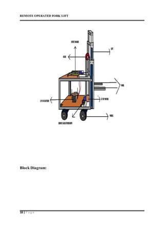
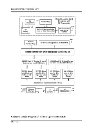
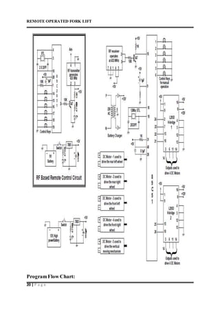
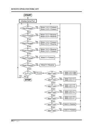
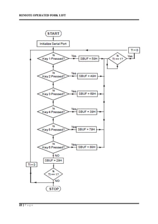
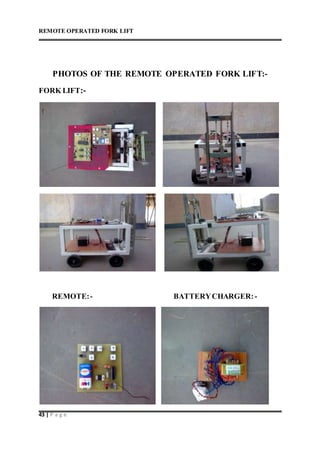
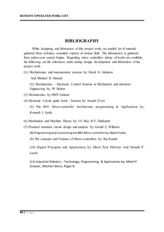

This document describes a remote operated forklift. It discusses how the forklift is operated through a remote control unit that uses radio frequency signals and microcontrollers to control the forklift's motors and movements. The forklift uses DC motors coupled to gears and chains to convert rotational motion to linear motion for lifting and lowering the forks, as well as driving the forklift in all directions. Safety protocols for operating forklifts are also mentioned.