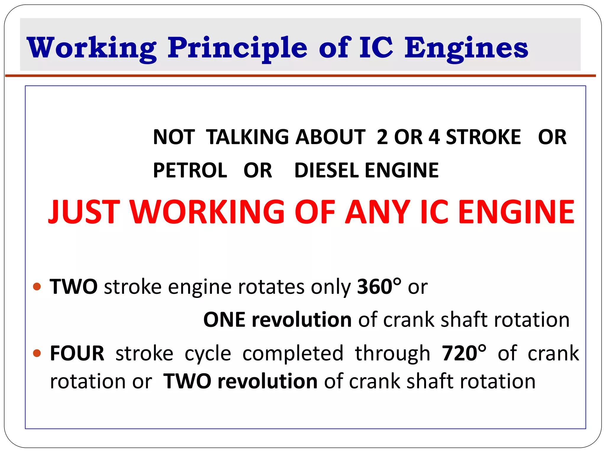
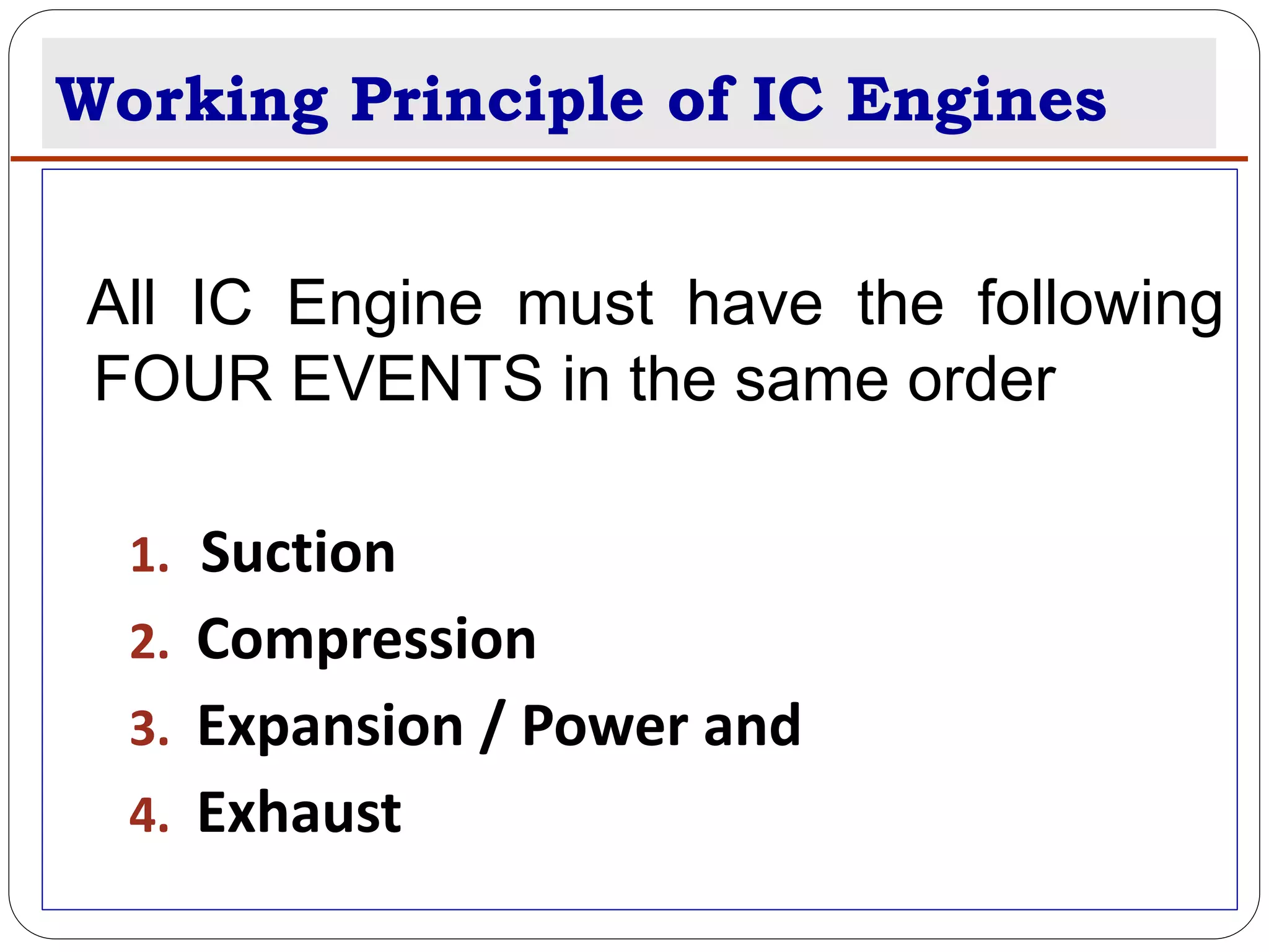
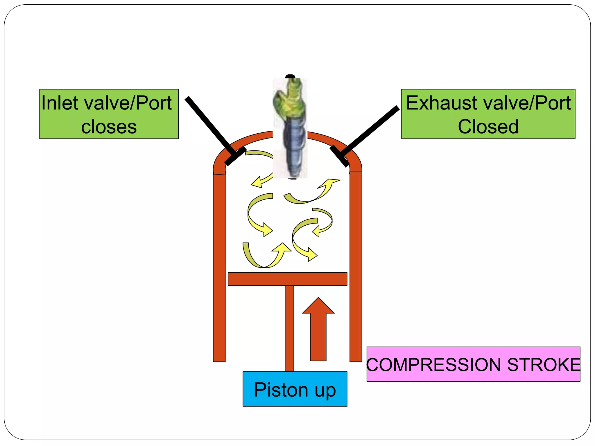
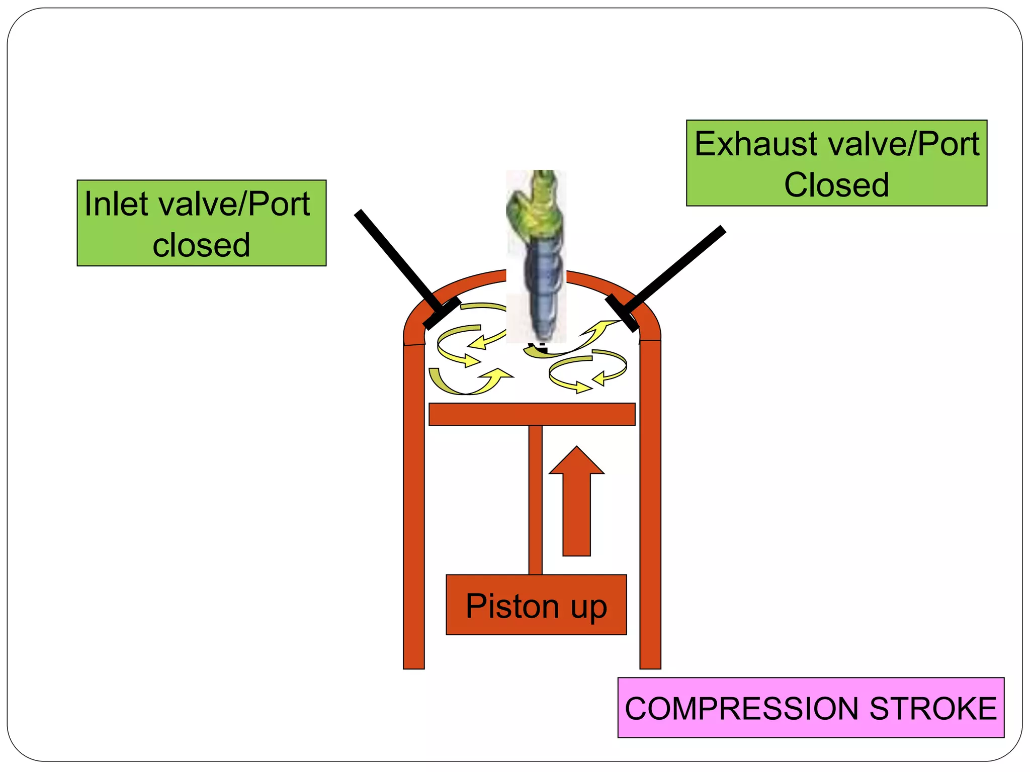
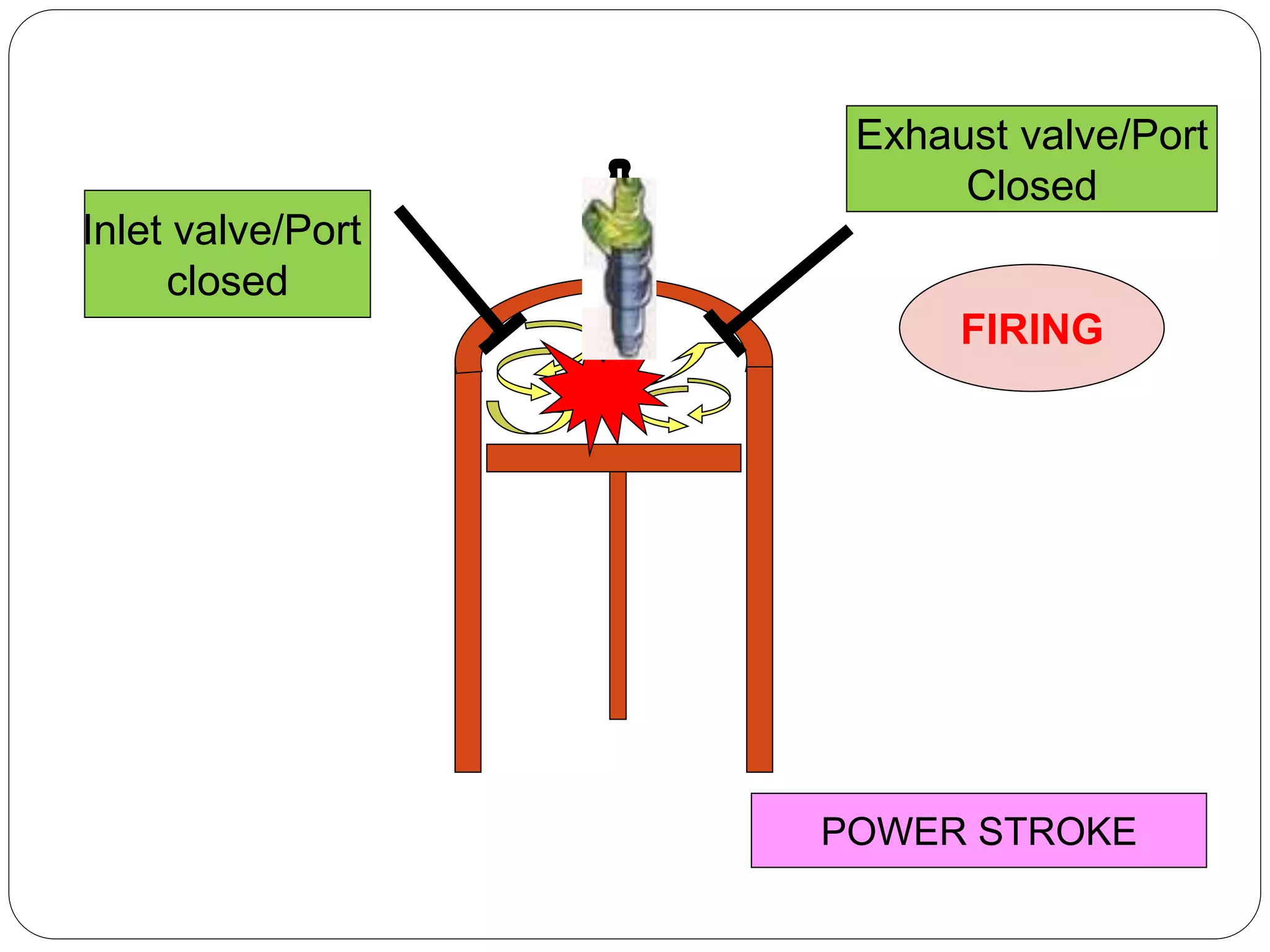
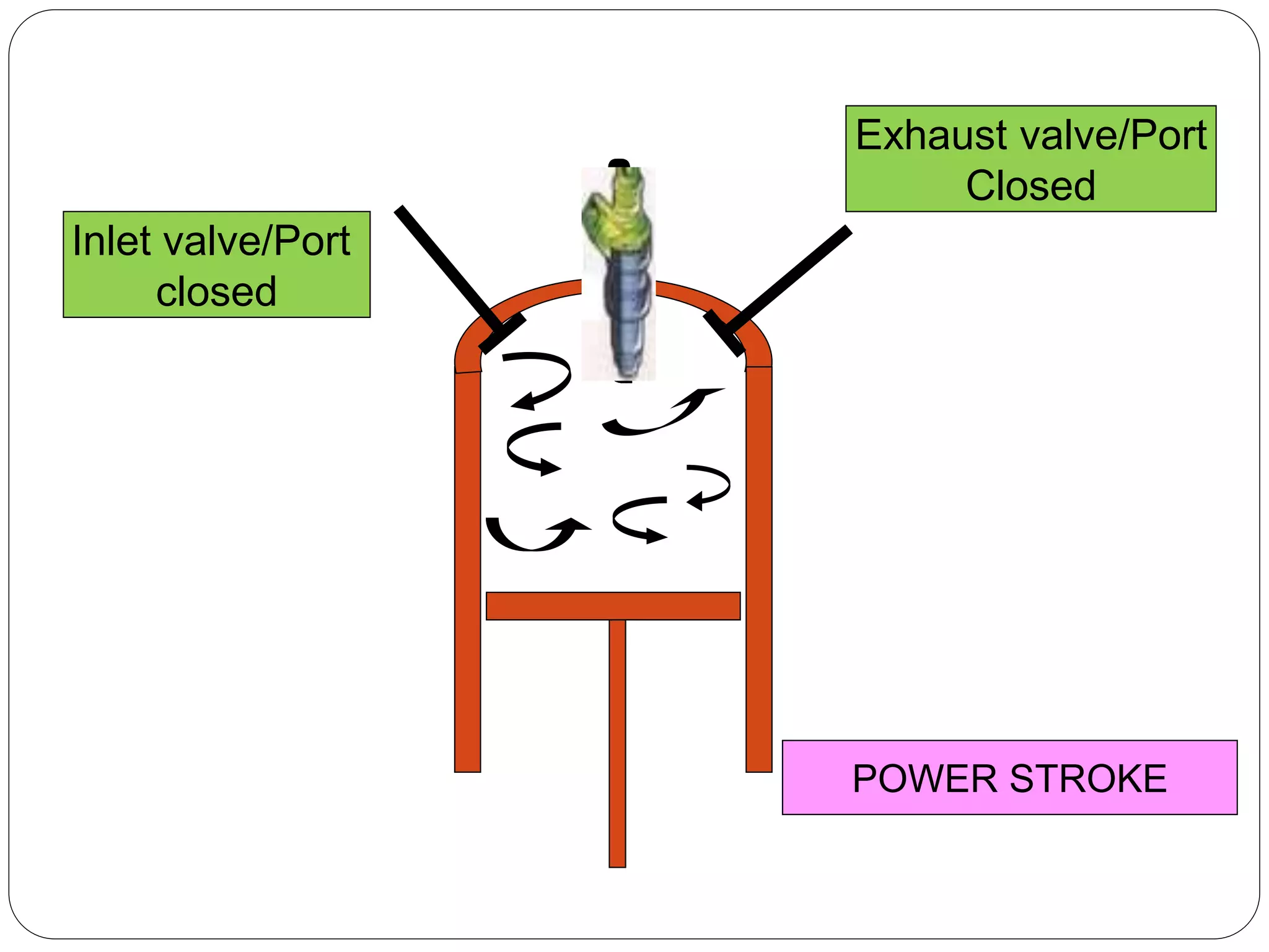
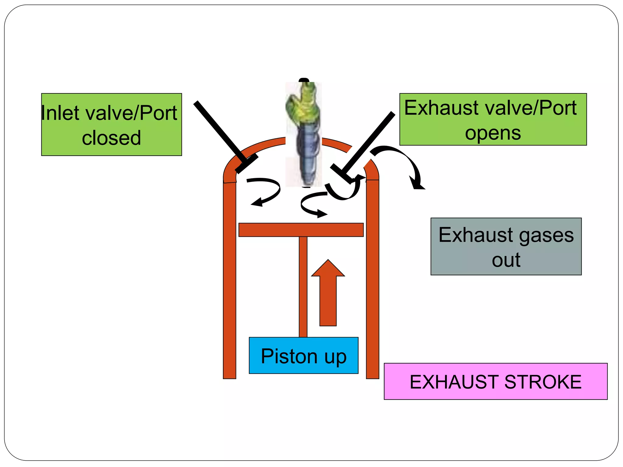
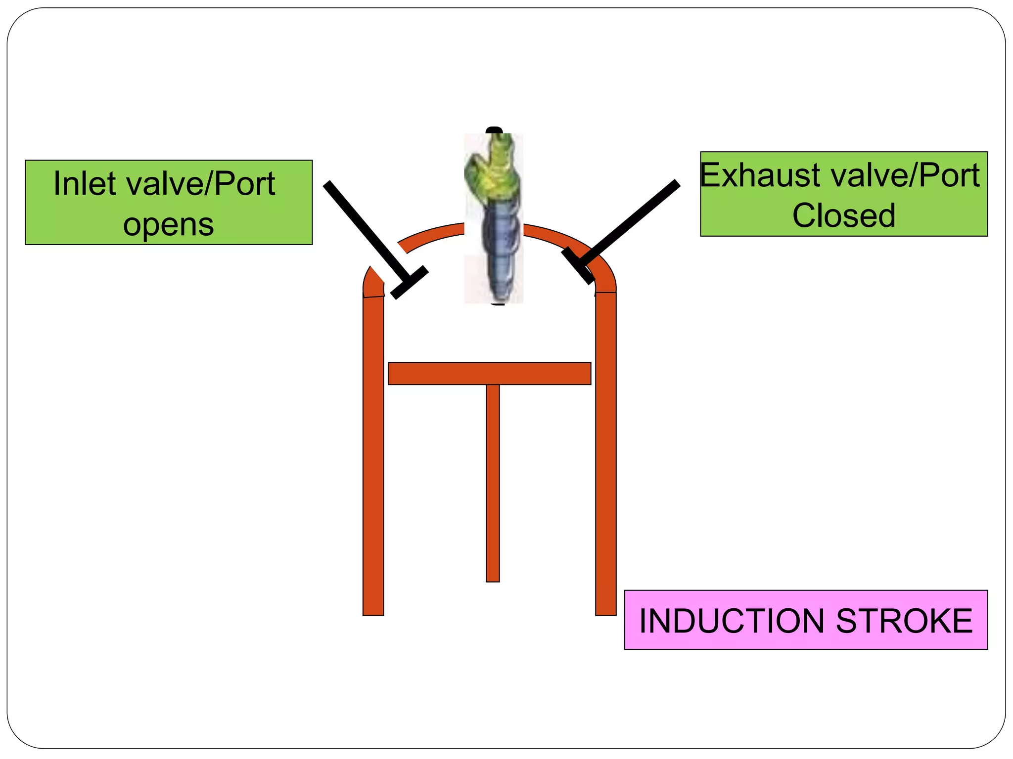
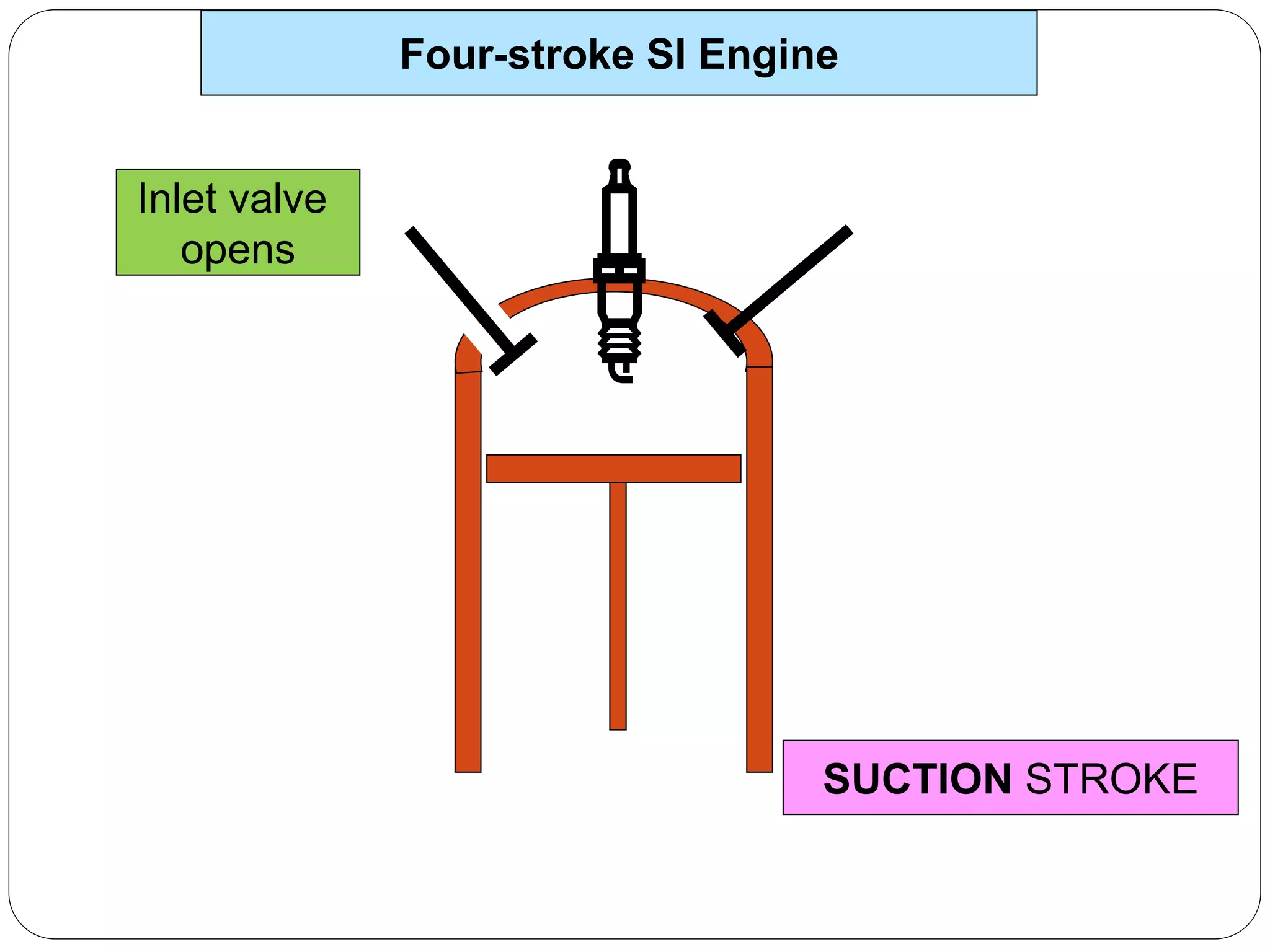
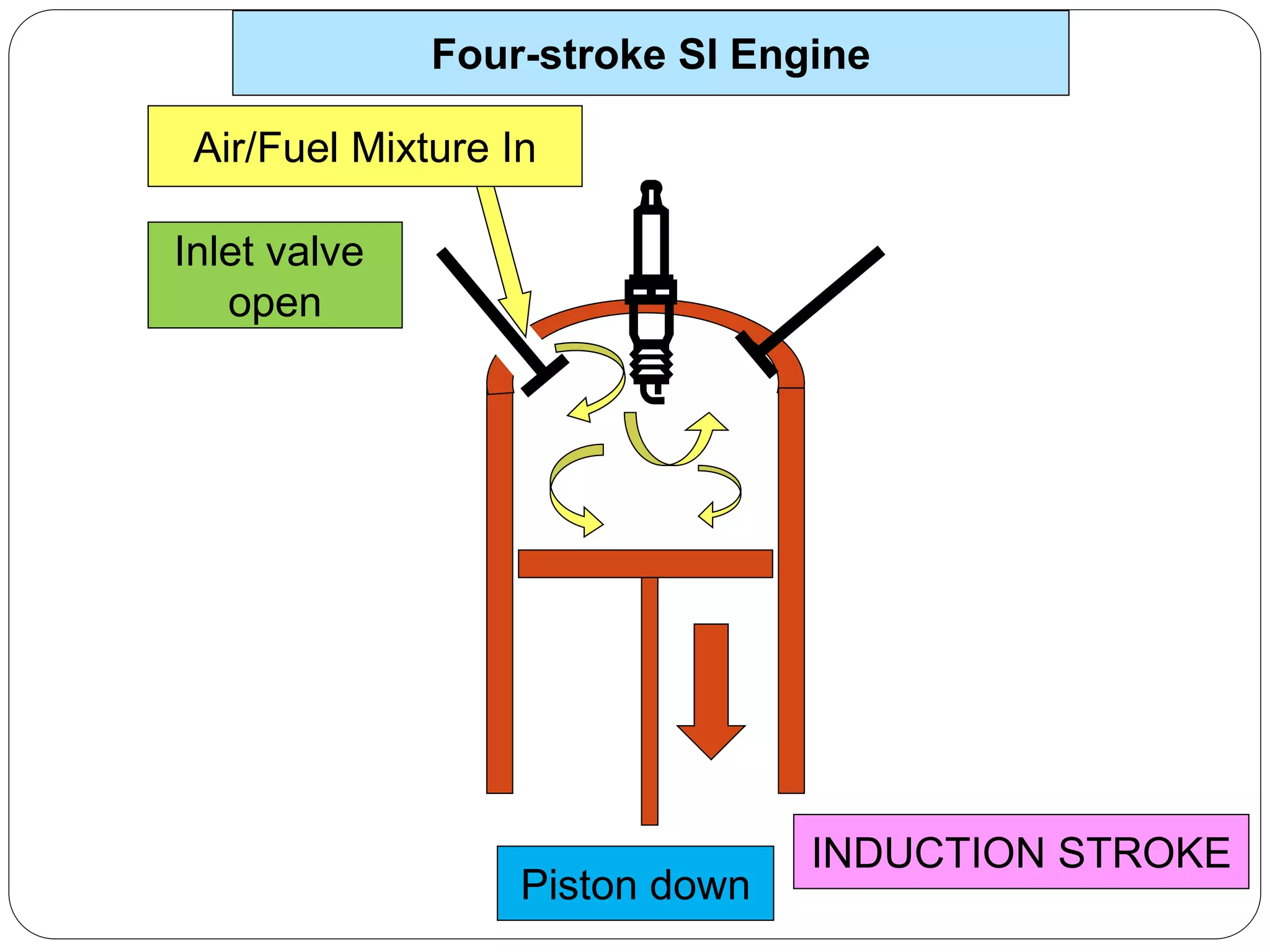
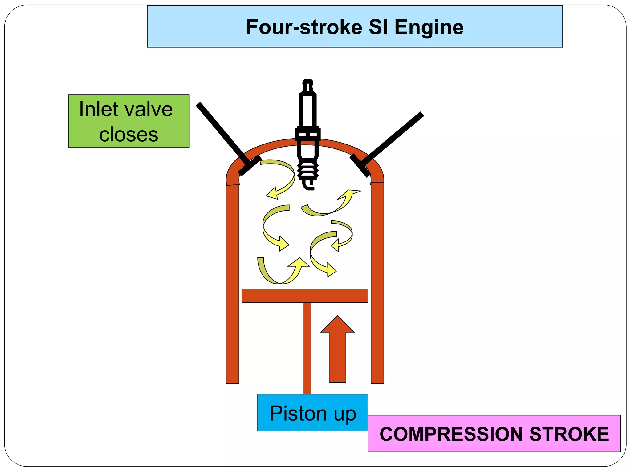
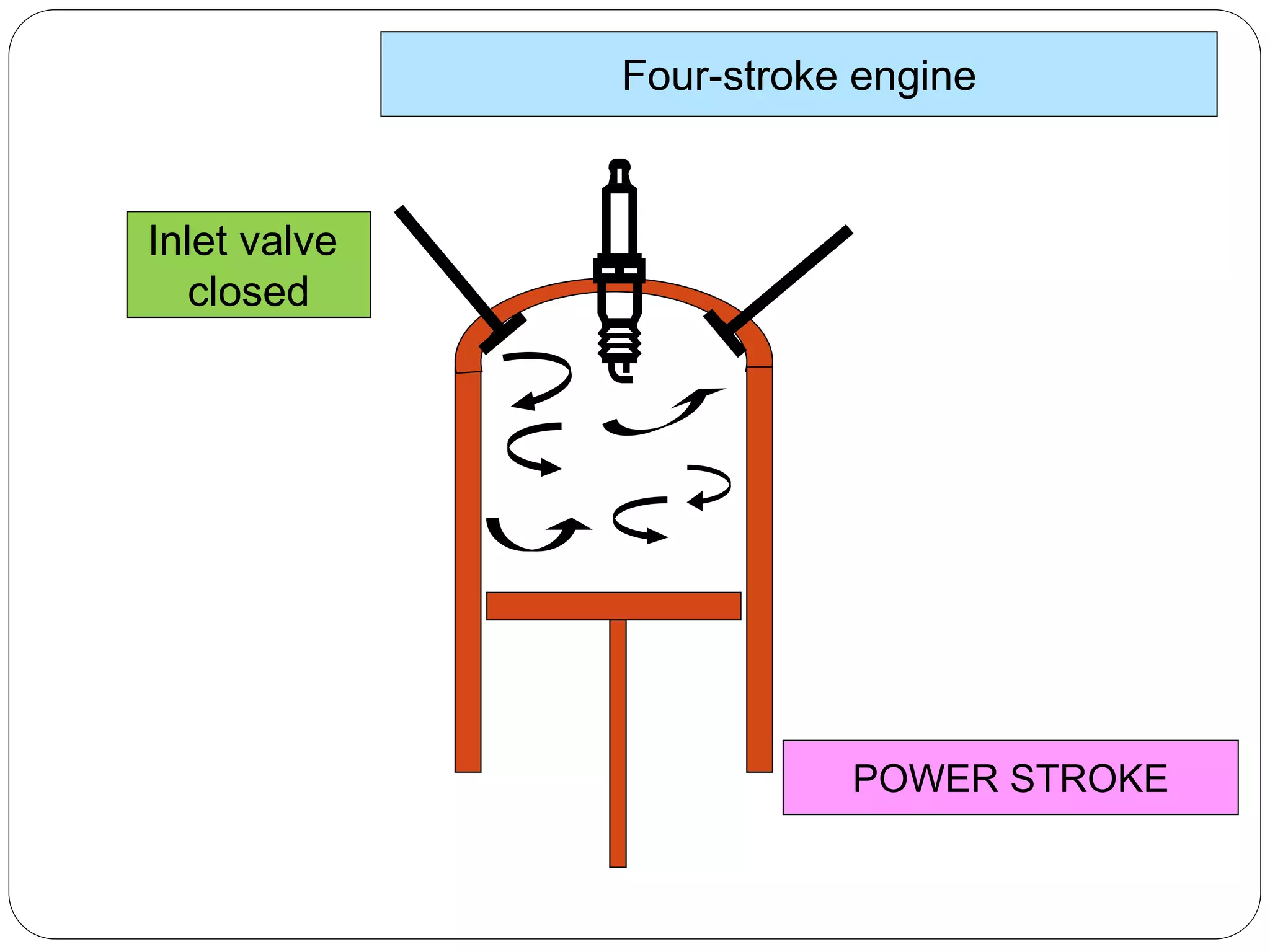
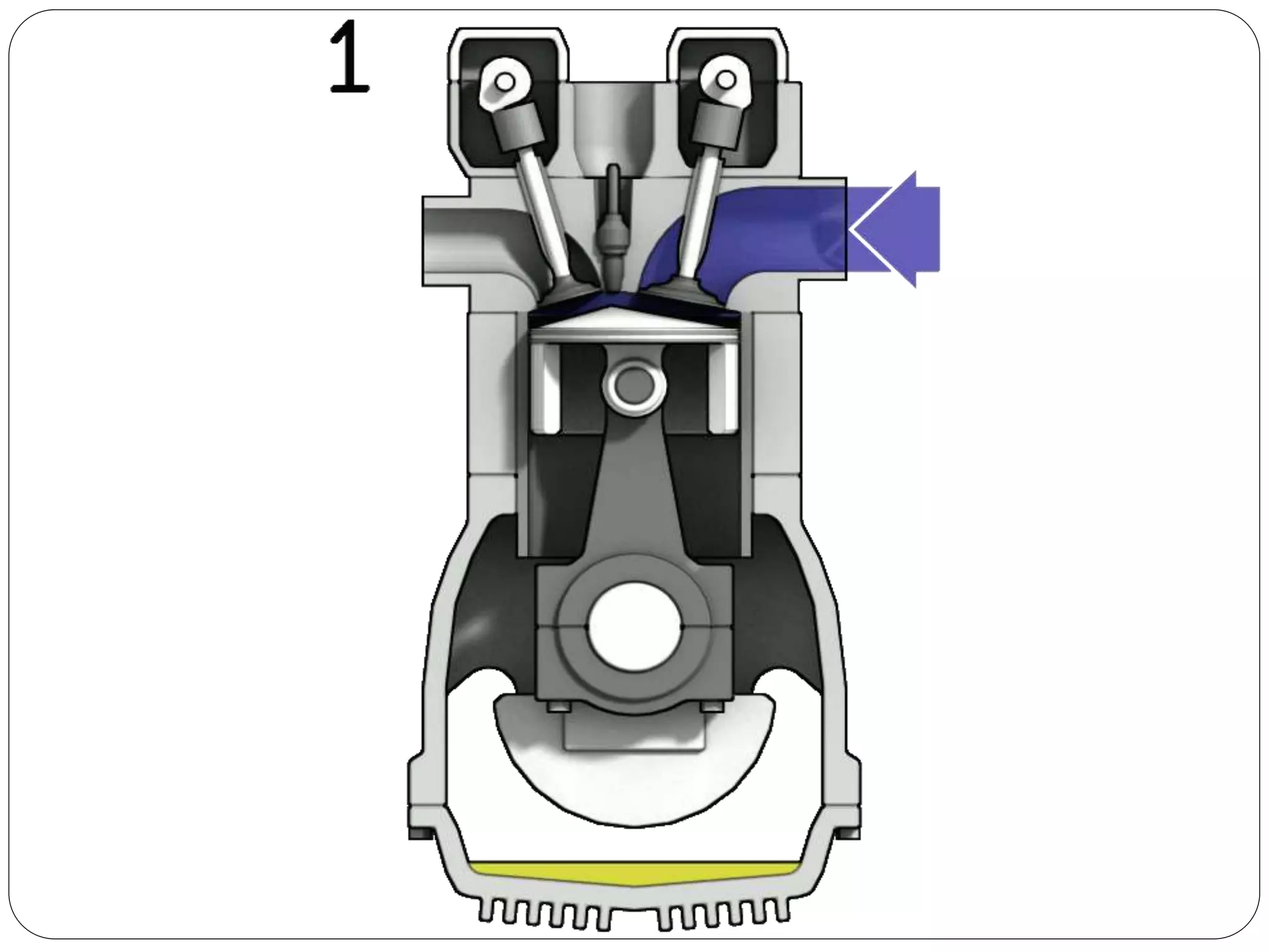
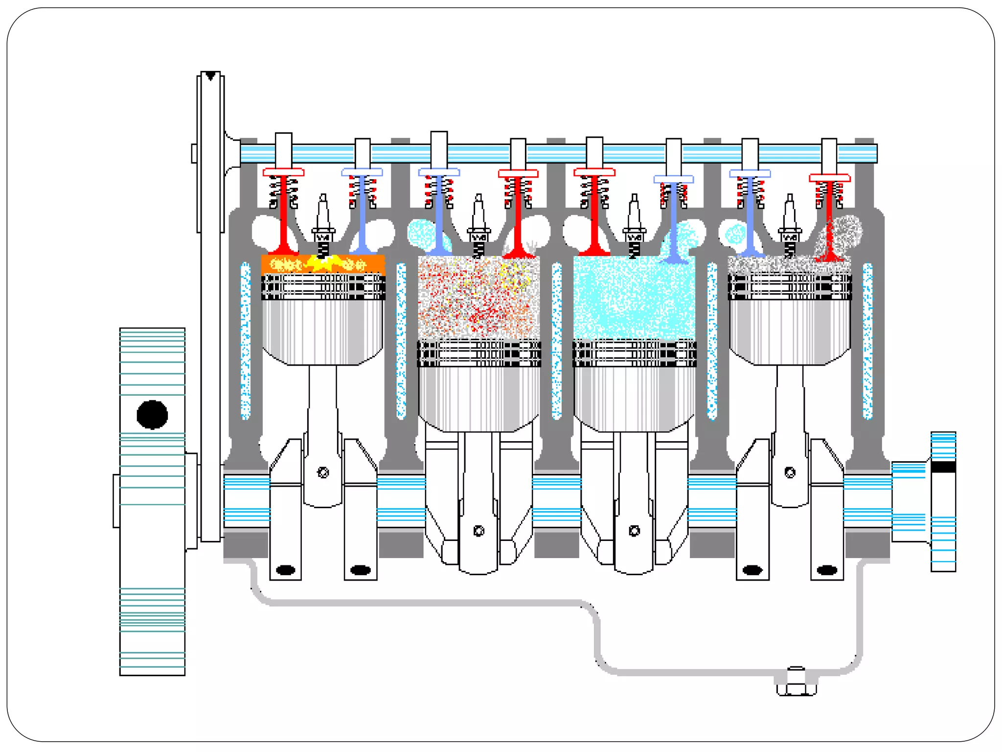
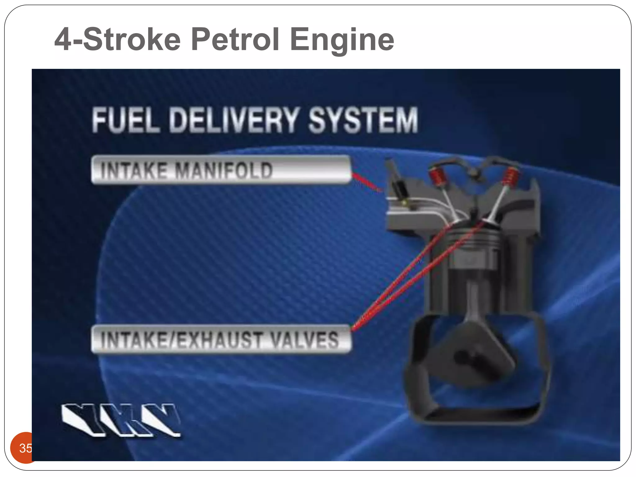
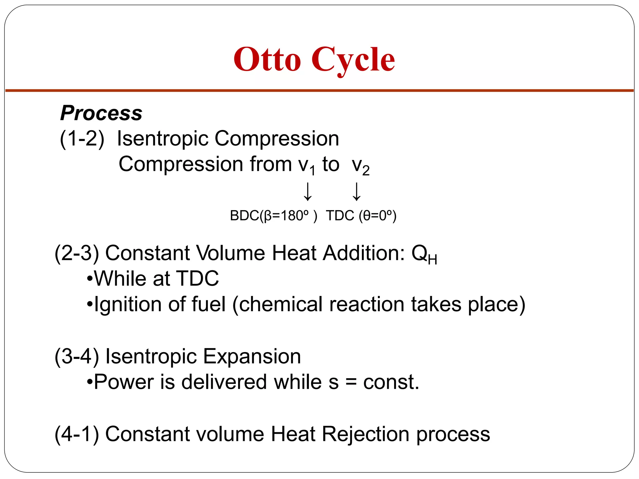
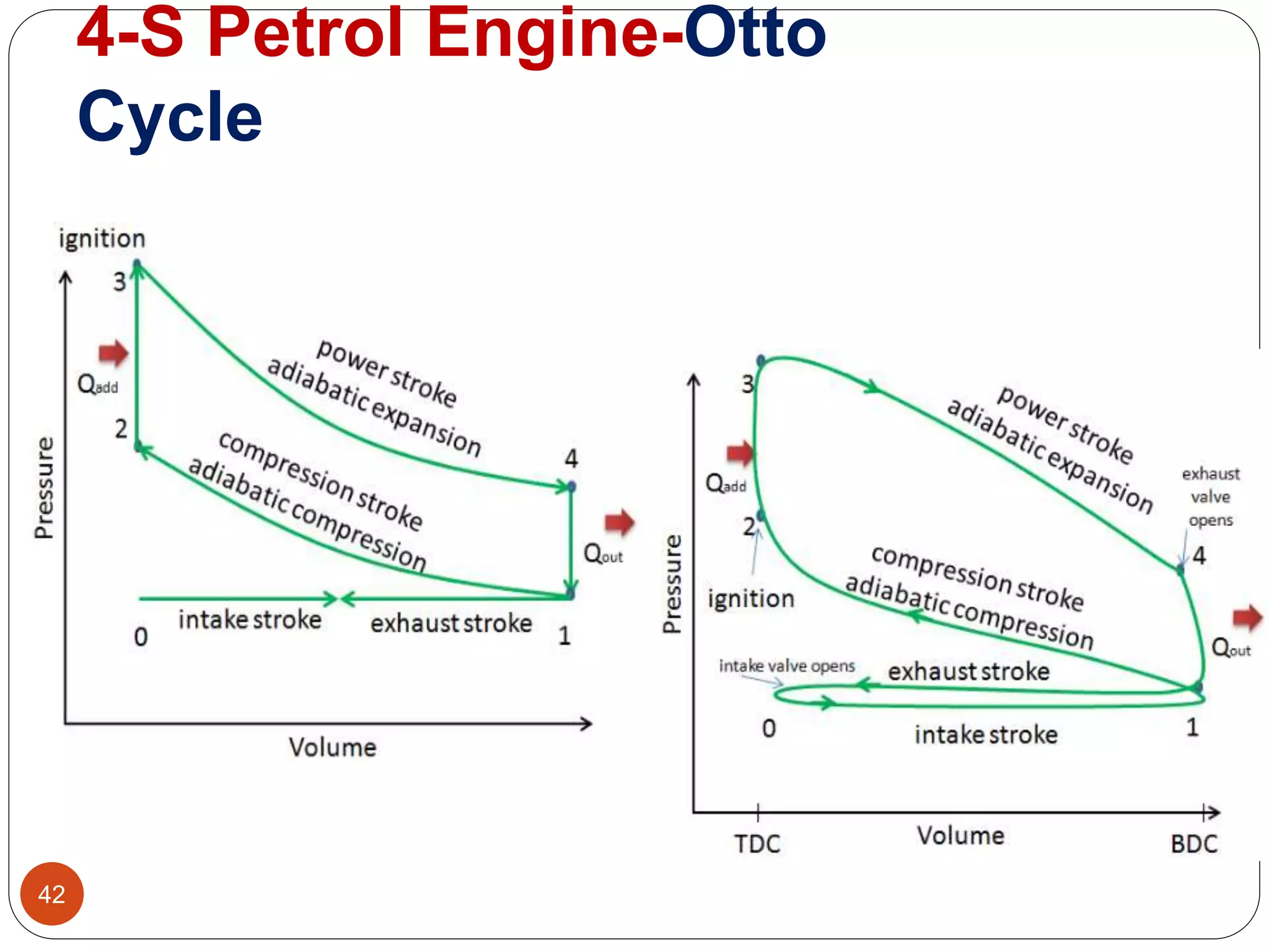
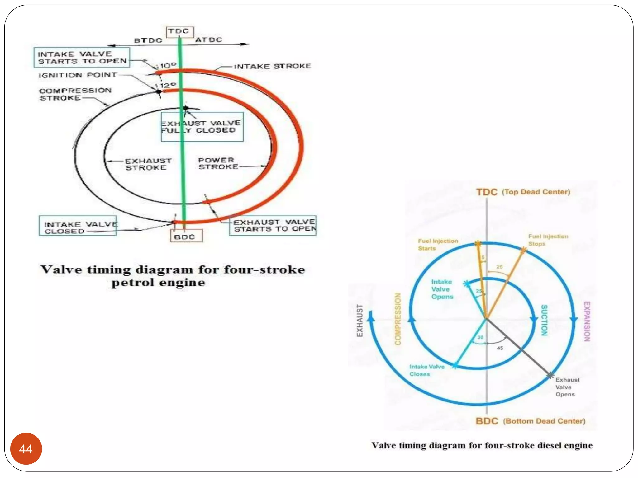
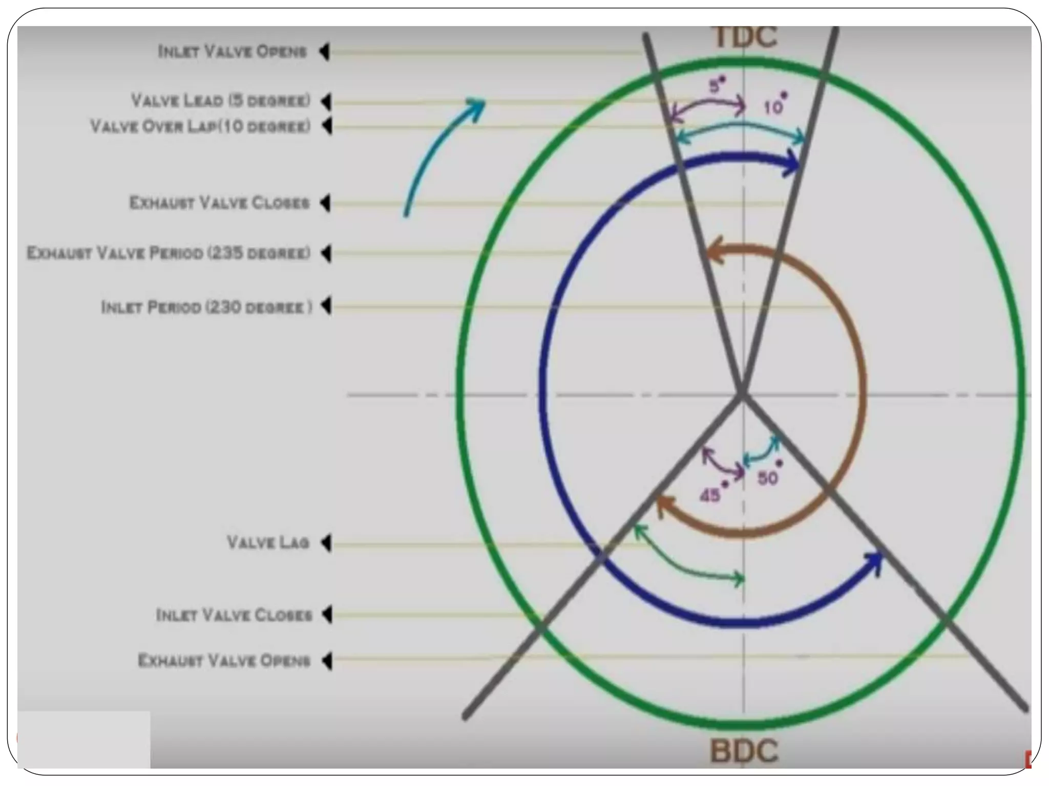
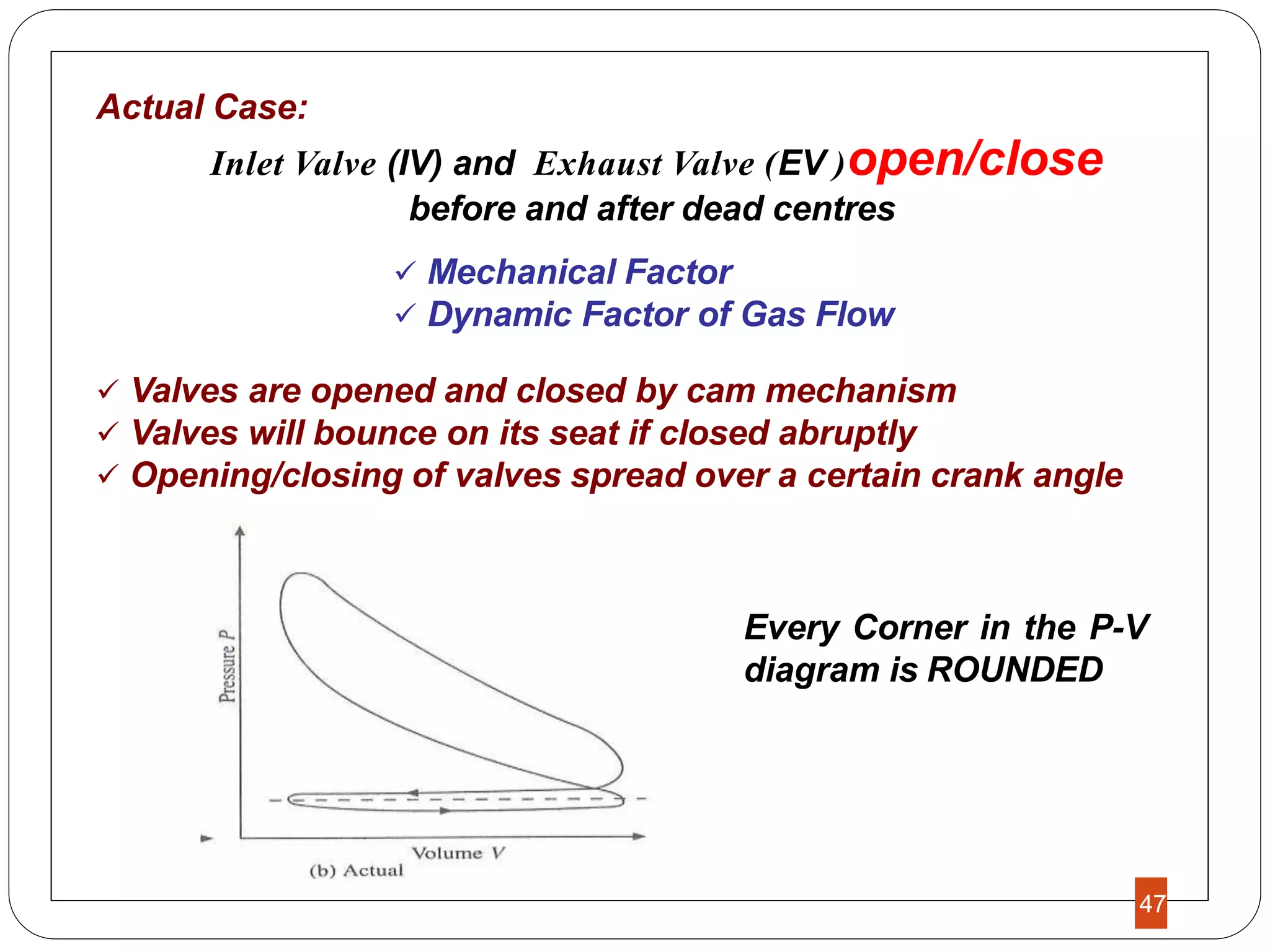
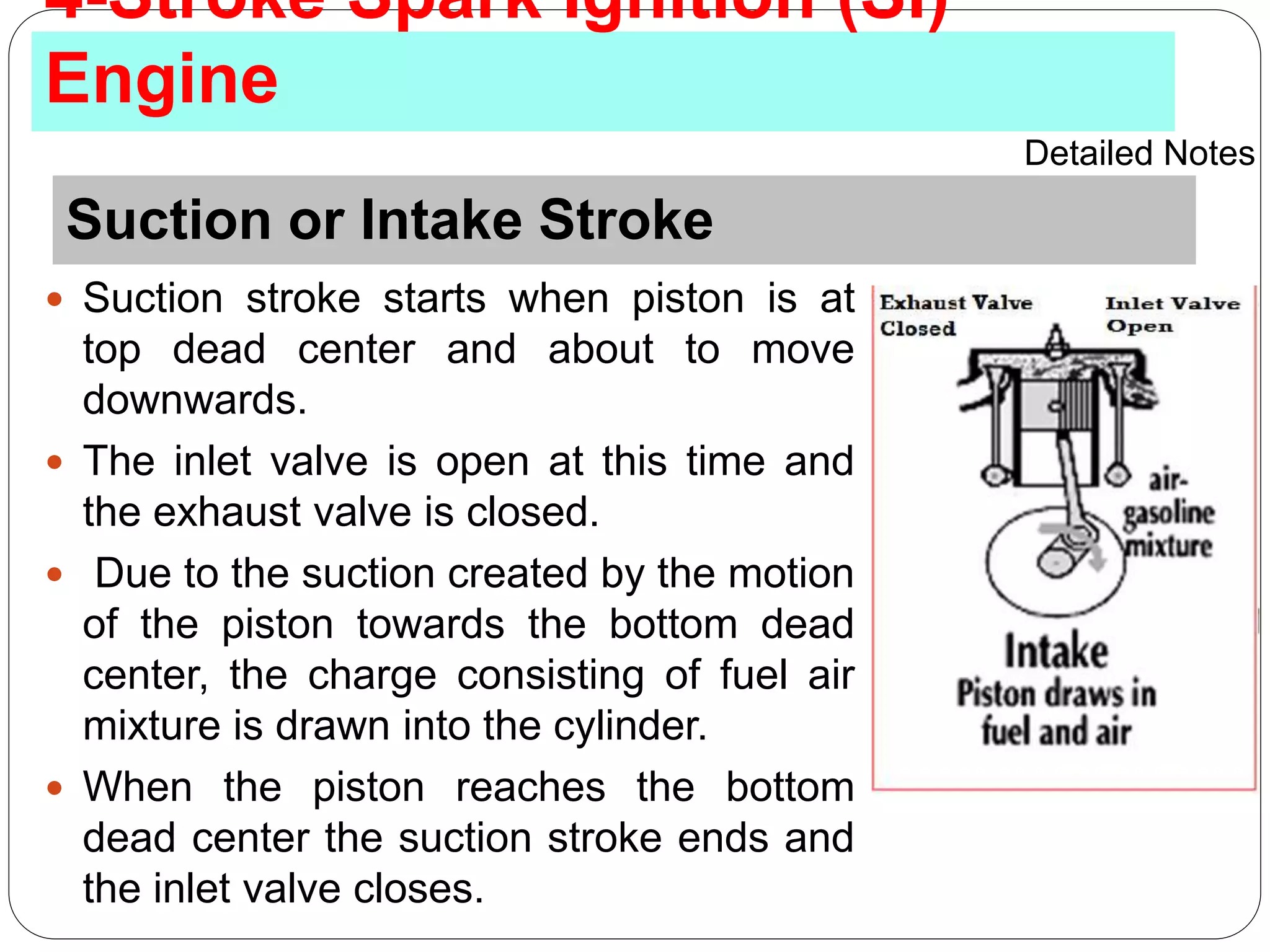
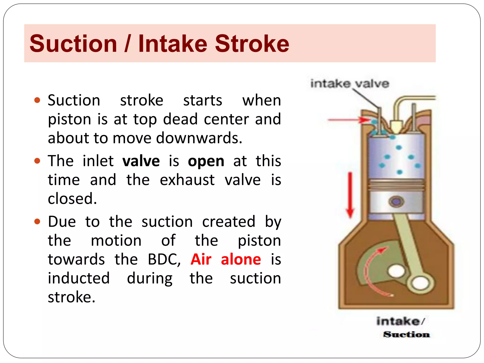
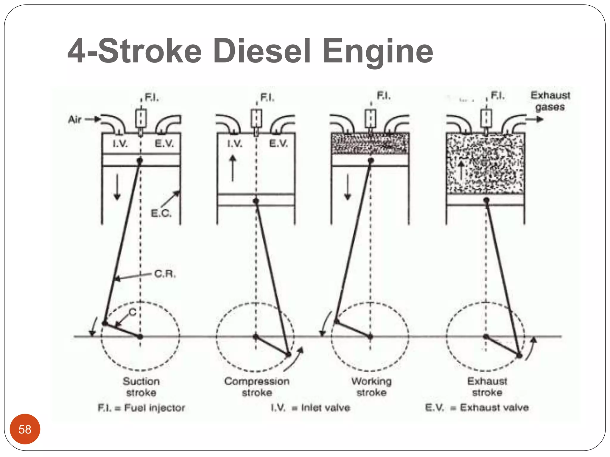
The document discusses the working principles of internal combustion engines. It begins by explaining that all IC engines must go through four strokes in a specific order: intake, compression, expansion/power, and exhaust. It then provides detailed descriptions and diagrams of how four-stroke petrol and diesel engines work through each stroke of the cycle. Key aspects covered include the valve timing, combustion processes, and thermodynamic cycles involved. Comparisons are made between two-stroke and four-stroke engines as well.
A brief explanation of both two stroke diesel engine and two stroke petrol engine with appropriate figures. It can also submitted to professor at the time of submission.
this is the ppt on 2 stroke and 4 stroke petrol engine. . i made this ppt with the help of dhrumil patel .who is in the L.D. college of engineering in chemical department. . i am very thankful to him for being my great partner. . .thanx dhrumil..
Definition of Supercharging ,
Effect of Supercharging ,
Need of Supercharging ,
Types of Supercharging
1) Centrifugal Supercharger
2) Rootes Supercharger
3) Vane Supercharger ,
Advantages & Disadvantages of Supercharging
Definition of Supercharging ,
Effect of Supercharging ,
Need of Supercharging ,
Types of Supercharging
1) Centrifugal Supercharger
2) Rootes Supercharger
3) Vane Supercharger ,
Advantages & Disadvantages of Supercharging
Internal Combustion Engines:- Heat Engines, Classification of heat engines, Construction and principle of IC Engines, Two stroke and Four stroke engine cycle.
This presentation is a part of IC engines online course where you will learn about the Four-stroke engine. All the slides are filled with related graphics to help you understand the concept easily.
Four stroke Petrol Engine (Hanan From UET pakistan)Hanan Mustafa
its about four stroke petrol engine...and in this presentation discuss about some impoertant parts of four stroke petrol engine.also explain in this presentation about the the stroke of engine...and their effiency .
Engine, classification of heat engine, classification of IC engine, component of IC engine, four stroke engine and 2- stroke engine, petrol and diesel engine, comparisons, terminology related to engine
Saudi Arabia stands as a titan in the global energy landscape, renowned for its abundant oil and gas resources. It's the largest exporter of petroleum and holds some of the world's most significant reserves. Let's delve into the top 10 oil and gas projects shaping Saudi Arabia's energy future in 2024.
Hierarchical Digital Twin of a Naval Power SystemKerry Sado
A hierarchical digital twin of a Naval DC power system has been developed and experimentally verified. Similar to other state-of-the-art digital twins, this technology creates a digital replica of the physical system executed in real-time or faster, which can modify hardware controls. However, its advantage stems from distributing computational efforts by utilizing a hierarchical structure composed of lower-level digital twin blocks and a higher-level system digital twin. Each digital twin block is associated with a physical subsystem of the hardware and communicates with a singular system digital twin, which creates a system-level response. By extracting information from each level of the hierarchy, power system controls of the hardware were reconfigured autonomously. This hierarchical digital twin development offers several advantages over other digital twins, particularly in the field of naval power systems. The hierarchical structure allows for greater computational efficiency and scalability while the ability to autonomously reconfigure hardware controls offers increased flexibility and responsiveness. The hierarchical decomposition and models utilized were well aligned with the physical twin, as indicated by the maximum deviations between the developed digital twin hierarchy and the hardware.
Explore the innovative world of trenchless pipe repair with our comprehensive guide, "The Benefits and Techniques of Trenchless Pipe Repair." This document delves into the modern methods of repairing underground pipes without the need for extensive excavation, highlighting the numerous advantages and the latest techniques used in the industry.
Learn about the cost savings, reduced environmental impact, and minimal disruption associated with trenchless technology. Discover detailed explanations of popular techniques such as pipe bursting, cured-in-place pipe (CIPP) lining, and directional drilling. Understand how these methods can be applied to various types of infrastructure, from residential plumbing to large-scale municipal systems.
Ideal for homeowners, contractors, engineers, and anyone interested in modern plumbing solutions, this guide provides valuable insights into why trenchless pipe repair is becoming the preferred choice for pipe rehabilitation. Stay informed about the latest advancements and best practices in the field.
CFD Simulation of By-pass Flow in a HRSG module by R&R Consult.pptxR&R Consult
CFD analysis is incredibly effective at solving mysteries and improving the performance of complex systems!
Here's a great example: At a large natural gas-fired power plant, where they use waste heat to generate steam and energy, they were puzzled that their boiler wasn't producing as much steam as expected.
R&R and Tetra Engineering Group Inc. were asked to solve the issue with reduced steam production.
An inspection had shown that a significant amount of hot flue gas was bypassing the boiler tubes, where the heat was supposed to be transferred.
R&R Consult conducted a CFD analysis, which revealed that 6.3% of the flue gas was bypassing the boiler tubes without transferring heat. The analysis also showed that the flue gas was instead being directed along the sides of the boiler and between the modules that were supposed to capture the heat. This was the cause of the reduced performance.
Based on our results, Tetra Engineering installed covering plates to reduce the bypass flow. This improved the boiler's performance and increased electricity production.
It is always satisfying when we can help solve complex challenges like this. Do your systems also need a check-up or optimization? Give us a call!
Work done in cooperation with James Malloy and David Moelling from Tetra Engineering.
More examples of our work https://www.r-r-consult.dk/en/cases-en/
Immunizing Image Classifiers Against Localized Adversary Attacksgerogepatton
This paper addresses the vulnerability of deep learning models, particularly convolutional neural networks
(CNN)s, to adversarial attacks and presents a proactive training technique designed to counter them. We
introduce a novel volumization algorithm, which transforms 2D images into 3D volumetric representations.
When combined with 3D convolution and deep curriculum learning optimization (CLO), itsignificantly improves
the immunity of models against localized universal attacks by up to 40%. We evaluate our proposed approach
using contemporary CNN architectures and the modified Canadian Institute for Advanced Research (CIFAR-10
and CIFAR-100) and ImageNet Large Scale Visual Recognition Challenge (ILSVRC12) datasets, showcasing
accuracy improvements over previous techniques. The results indicate that the combination of the volumetric
input and curriculum learning holds significant promise for mitigating adversarial attacks without necessitating
adversary training.
Immunizing Image Classifiers Against Localized Adversary Attacks
Four Stroke SI and CI engines
1. I.C. Engines
4 Stroke Petrol & Diesel Engines
1
Dr. S. VIJAYA BHASKAR
Professor in Mechanical Engineering
Sreenidhi Institute of Science &
Technology, Hyderabad
2. Working Principle of IC Engines
NOT TALKING ABOUT 2 OR 4 STROKE OR
PETROL OR DIESEL ENGINE
JUST WORKING OF ANY IC ENGINE
TWO stroke engine rotates only 360 or
ONE revolution of crank shaft rotation
FOUR stroke cycle completed through 720 of crank
rotation or TWO revolution of crank shaft rotation
3. Working Principle of IC Engines
All IC Engine must have the following
FOUR EVENTS in the same order
1. Suction
2. Compression
3. Expansion / Power and
4. Exhaust
38. Power Cycle: Otto cycle
The air standard Otto Cycle is an ideal cycle that
approximates a spark- ignition internal combustion engine.
It assumes that the heat addition occurs instantaneously
while the piston is at TDC.
39. Process
(1-2) Isentropic Compression
Compression from ν1 to v2
↓
BDC(β=180º )
↓
TDC (θ=0º)
(2-3) Constant Volume Heat Addition: QH
•While at TDC
•Ignition of fuel (chemical reaction takes place)
(3-4) Isentropic Expansion
•Power is delivered while s = const.
(4-1) Constant volume Heat Rejection process
Otto Cycle
41. Process 1–2 is an isentropic compression of the air as the
piston moves from bottom dead center to top dead center.
Process 2–3 is a constant-volume heat transfer to the air
from an external source while the piston is at top dead
center. This process is intended to represent the ignition of
the fuel–air mixture and the subsequent rapid burning.
Process 3–4 is an isentropic expansion (power stroke).
Process 4–1 completes the cycle by a constant-volume
process in which heat is rejected from the air while the
piston is at bottom dead center.
46. Typical Theoretical P-V and Valve Timing Diagrams of a Four-
Stroke Spark Ignition Engine
46
Observations:
P-V diagram shows sharp edges
i.e., valves open/close instantaneously at dead centres
47. Actual Case:
Inlet Valve (IV) and Exhaust Valve (EV )open/close
before and after dead centres
Mechanical Factor
Dynamic Factor of Gas Flow
Valves are opened and closed by cam mechanism
Valves will bounce on its seat if closed abruptly
Opening/closing of valves spread over a certain crank angle
Every Corner in the P-V
diagram is ROUNDED
47
48. Suction or Intake Stroke
Suction stroke starts when piston is at
top dead center and about to move
downwards.
The inlet valve is open at this time and
the exhaust valve is closed.
Due to the suction created by the motion
of the piston towards the bottom dead
center, the charge consisting of fuel air
mixture is drawn into the cylinder.
When the piston reaches the bottom
dead center the suction stroke ends and
the inlet valve closes.
4-Stroke Spark Ignition (SI)
Engine
Detailed Notes
49. Compression Stroke
The charge taken into the cylinder during the
suction stroke is compressed by the return
stroke of the piston.
During this stroke both inlet and exhaust
valves are in closed position. The mixture
which fills the entire cylinder volume is now
compressed into the clearance volume.
At the end of the compression stroke the
mixture is ignited with the help of a spark plug
located on the cylinder head. During the
burning process the chemical energy of the
fuel is converted into heat energy.
The pressure at the end of the combustion
process is considerably increased due to heat
from the fuel.
50. Expansion or Power Stroke
The high pressure of the burnt
gases forces the piston towards
the BDC, both the valves are in
closed position. Of the four strokes
only during this stroke power is
produced.
Both pressure and temperature
decrease during expansion.
51. Exhaust Stroke
At the end of the expansion stroke
the exhaust valve opens and the
inlet valve remains closed.
The pressure falls to atmospheric
level a part of the burnt gases
escape.
The piston starts moving from the
bottom dead center to top dead
center and sweeps the burnt gases
out from the cylinder almost at
atmospheric pressure.
The exhaust valve closes when the
piston reaches TDC.
52. Four Stroke Diesel / CI
Engine
Diesel Engine was invented by Rudolph Diesel.
It is ignited by compression of charge, so it’s also
called as compression ignition (CI) engine.
It is similar to four stroke petrol engine but operates at a
much higher compression ratio. The compression ratio of an
SI engine is between 6 and 10:1 while for a CI engine it is
from 16 to 20:1.
A high pressure fuel injector is used to inject the fuel into
the combustion chamber.
53. Suction / Intake Stroke
Suction stroke starts when
piston is at top dead center and
about to move downwards.
The inlet valve is open at this
time and the exhaust valve is
closed.
Due to the suction created by
the motion of the piston
towards the BDC, Air alone is
inducted during the suction
stroke.
54. Compression Stroke
Air inducted during the suction
stroke is compressed into the
clearance volume due to return
stroke of piston.
Both valves remain closed
during this stroke.
The air in the combustion
chamber is at high
temperature and high pressure
with a decrease in volume.
Both Valves Closed
55. Expansion Stroke or Power
Stroke
At the end of compression stroke, the
fuel is injected into the cylinder in the
form of fine spray through the nozzle and
is ignited by the temperature of hot
compressed air in the chamber.
So that combustion process is started at
the end of compression stroke.
The combustion of gases expands inside
the cylinder so that piston start to move
towards BDC.
Both the valves remain closed during this
stroke
Both Valves Closed
57. Exhaust Stroke
The piston traveling from
BDC to TDC pushes out
the product of
combustion.
The exhaust valve is
open and the intake
valve is closed during
this stroke.
60. S
N
o
Four Stroke Engine Two Stroke Engine
1. The thermodynamic cycle
is completed in four strokes
of the piston or in two
revolutions of crank shaft
or 720° of crank angle.
The thermodynamic cycle is
completed in two strokes of
the piston or in one
revolution of the crank shaft
or 3600 of crank angle
2. One power stroke is
obtained in every two
revolution of crank shaft /
4-strokes of the Piston.
One power stroke is obtained
in each revolution of crank
shaft.
3. Because of above, turning
moment is not so uniform
and hence a heavier
flywheel is needed.
Because of above, turning
moment is more uniform and
hence a lighter flywheel can
be used.
4. Power produced for same
size of engine is less. In
Power produced for same size
of engine is twice, or for same
61. S.
N
o
Four Stroke Engine Two Stroke Engine
5. Lesser cooling and lubrication
requirements. Lower rate of wear
and tear.
Greater cooling and lubrication
requirements. Higher rate of wear
and tear.
6. It has valves and valve actuating
mechanisms for opening and
closing of the intake and exhaust
valves.
It has no valves but only ports
7. Because of comparatively higher
weight and complicated valve
mechanism, the initial cost of the
engine is more.
Because of light weight and
simplicity due to the absence of
valve actuating mechanism, initial
cost of the engine is less.
8. Volumetric efficiency is more due
to more time for induction.
Volumetric efficiency is low due to
lesser time for induction.
9. Thermal efficiency is higher, part
load efficiency is better.
Thermal efficiency is lower, part
load efficiency is poor.
1
0.
Application : Cars, Buses, Trucks,
Tractors, Aero planes and Power
Application : Mopeds, Scooters,
Motorcycles, Hand sprayers etc.,