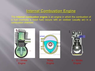
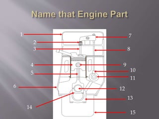
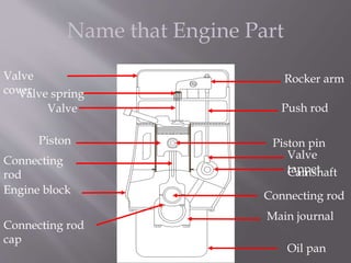
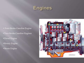
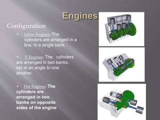
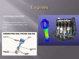
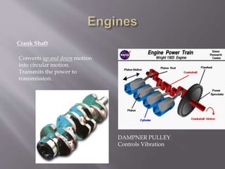
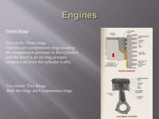
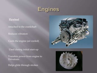
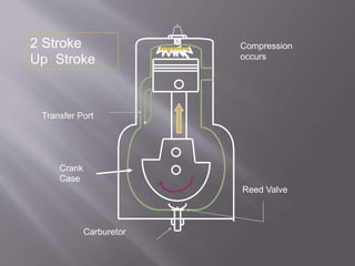
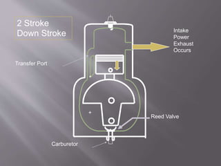
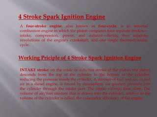
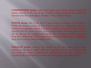
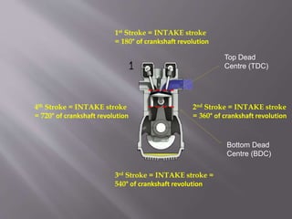
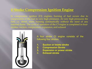
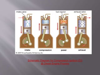
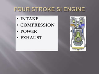
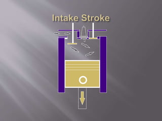
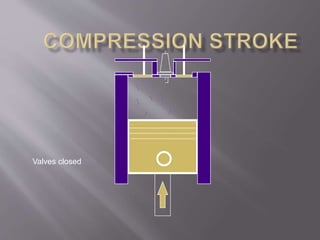
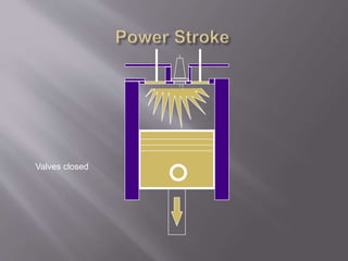
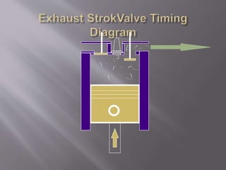
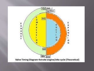
The document discusses internal combustion engines, including their basic components and operating cycles. It describes the four main strokes of a four-stroke engine: intake, compression, power, and exhaust. It also summarizes the operation of two-stroke engines and differences from four-stroke engines, such as using crankcase compression and ports instead of valves. Additionally, it covers the classification of engines as spark ignition or compression ignition and compares their combustion processes.
3. Internal Combustion Engine: S.I. and C.I. engines of two and
four stroke cycles,
real cycle analysis of SI and CI engines,
determination of engine dimensions, speed, fuel
consumption, output, mean effective pressure, efficiency,
factors effecting volumetric efficiency,
heat balance, performance characteristics of SI and CI
engines, cylinder arrangement, firing order, power balance
for multi-cylinder engines,
valve timing.
4. engine that converts chemical energy in a fuel into mechanical
energy, usually made available on a rotating output shaft.
Chemical energy of the fuel is first converted to thermal energy by
means of combustion or oxidation with air inside the engine. This
thermal energy raises the temperature and pressure of the gases
within the engine, and the high-pressure gas then expands against
the mechanical mechanisms of the engine. This expansion is
converted by the mechanical linkages of the engine to a rotating
crankshaft, which is the output of the engine.
5. The internal combustion engine is an engine in which the combustion of
a fuel (normally a fossil fuel) occurs with an oxidizer (usually air) in a
combustion chamber.
2 – Stroke
Engine
Rotay
Engine
4 – Stroke
Engine
6. External Combustion Engine
An external combustion engine (EC engine) is a heat engine where an
(internal) working fluid is heated by combustion in an external source,
through the engine wall or a heat exchanger. The fluid then, by expanding
and acting on the mechanism of the engine, produces motion and usable
work. The fluid is then cooled, compressed and reused (closed cycle), or
(less commonly) dumped, and cool fluid pulled in (open cycle air engine).
Lokomotif engine Jet Engine
7. Reciprocating Engine
A reciprocating engine, also often known as a piston engine, is a heat
engine that uses one or more reciprocating pistons to convert pressure
into a rotating motion. This article describes the common features of all
types. The main types are: the internal combustion engine, used
extensively in motor vehicles; the steam engine, the mainstay of the
Industrial Revolution; and the niche application Stirling engine.
Stirling Engine 4 Stroke Engine 2 Stroke Engine
8. Rotary Engine
A rotary engine is essentially a standard Otto cycle engine, but instead of
having a fixed cylinder block with rotating crankshaft as with a conventional
radial engine, the crankshaft remains stationary and the entire cylinder
block rotates around it. In the most common form, the crankshaft was fixed
solidly to an aircraft frame, and the propeller simply bolted onto the front of
the crankcase.
9. Normally IC engines are classified into
C.I engines and
S.I engines
10. Some of the important classifications are given
below,
1. Number of strokes
-two stroke and four stroke
2. Working Cycles
-Otto ,Diesel, Dual cycle
3. Cylinder arrangement
-In-line, V-type, Opposed, Radial
14. Name that Engine Part
Valve
coverValve spring
Valve
Connecting
rod
Engine block
Rocker arm
Push rod
Valve
tappetCamshaft
Connecting rod
Main journal
Connecting rod
cap
Piston pin
Oil pan
Piston
16. Configuration
• Inline Engines: The
cylinders are arranged in a
line, in a single bank.
• V Engines: The cylinders
are arranged in two banks,
set at an angle to one
another.
• Flat Engines: The
cylinders are
arranged in two
banks on opposite
sides of the engine
17. Parts
•Exhaust Valve lets the exhaust gases escape the combustion
Chamber. (Diameter is smaller then Intake valve)
•Intake Valve lets the air or air fuel mixture to enter the
combustion chamber. (Diameter is larger than the exhaust valve)
Valves: Minimum
Two Valves pre Cylinder
18. Valve Springs: Keeps the valves
Closed.
Valve Lifters: Rides the cam lobe
and helps in opening the valves.
20. Cam Shaft: The shaft that has intake and
Exhaust cams for operating the valves.
Cam Lobe: Changes rotary motion
into reciprocating motion.
21. It provides the means of ignition when
the gasoline engine’s piston is at the end
of compression stroke, close to
Top Dead Center(TDC)
Spark Plug
The difference between a
"hot" and a "cold" spark
plug is that the ceramic tip
is longer on the
hotter plug.
22. Piston
A movable part fitted into a
cylinder, which can receive and
transmit power.
Through connecting rod, forces
the crank shaft to rotate.
23. Cylinder head
Part that covers and encloses the
Cylinder.
It contains cooling fins or water jackets
and the valves.
Some engines contains the cam shaft
in the cylinder head.
24. Engine Block
Foundation of the engine and
contains pistons, crank shaft,
cylinders, timing sprockets and
sometimes the cam shaft.
26. Crank Shaft
Converts up and down motion
into circular motion.
Transmits the power to
transmission.
DAMPNER PULLEY
Controls Vibration
27. Piston Rings
Four stroke: Three rings
Top two are compression rings (sealing
the compression pressure in the cylinder)
and the third is an oil ring (scrapes
excessive oil from the cylinder walls)
Two Stroke: Two Rings
Both the rings are Compression rings.
28. Flywheel
Attached to the crankshaft
Reduces vibration
Cools the engine (air cooled)
Used during initial start-up
Transfers power from engine to
Drivetrain
Helps glide through strokes
29. 2 Stroke Spark Ignition Engine
A two-stroke engine is an internal combustion engine that completes the
process cycle in one revolution of the crankshaft (an up stroke and a down
stroke of the piston, compared to twice that number for a four-stroke
engine).
This is accomplished by using the end of the combustion stroke and the
beginning of the compression stroke to perform simultaneously the intake
and exhaust (or scavenging) functions.
In this way, two-stroke engines often provide high specific power, at least in
a narrow range of rotational speeds.
The functions of some or all of the valves required by a four-stroke engine
are usually served in a two-stroke engine by ports that are opened and
closed by the motion of the piston(s), greatly reducing the number of
moving parts.
30. Working Priciple of 2 Stroke Spark Ignition Engine
Intake
The fuel/air mixture is first drawn into the crankcase
by the vacuum that is created during the upward
stroke of the piston. The illustrated engine features
a poppet intake valve; however, many engines use
a rotary value incorporated into the crankshaft.
Crankcase compression
During the downward stroke, the poppet valve is
forced closed by the increased crankcase pressure.
The fuel mixture is then compressed in the
crankcase during the remainder of the stroke.
31. Transfer/Exhaust
Toward the end of the stroke, the piston exposes the
intake port, allowing the compressed fuel/air mixture in
the crankcase to escape around the piston into the main
cylinder. This expels the exhaust gasses out the exhaust
port, usually located on the opposite side of the cylinder.
Unfortunately, some of the fresh fuel mixture is usually
expelled as well.
Compression
The piston then rises, driven by flywheel momentum, and
compresses the fuel mixture. (At the same time, another
intake stroke is happening beneath the piston).
Power
At the top of the stroke, the spark plug ignites the fuel
mixture. The burning fuel expands, driving the piston
downward, to complete the cycle. (At the same time,
another crankcase compression stroke is happening
beneath the piston.)
37. 4 Stroke Spark Ignition Engine
A four-stroke engine, also known as four-cycle, is an internal
combustion engine in which the piston completes four separate strokes—
intake, compression, power, and exhaust—during two separate
revolutions of the engine's crankshaft, and one single thermodynamic
cycle.
Working Priciple of 4 Stroke Spark Ignition Engine
INTAKE stroke: on the intake or induction stroke of the piston, the piston
descends from the top of the cylinder to the bottom of the cylinder,
reducing the pressure inside the cylinder. A mixture of fuel and air, or just
air in a diesel engine, is forced by atmospheric (or greater) pressure into
the cylinder through the intake port. The intake valve(s) then close. The
volume of air/fuel mixture that is drawn into the cylinder, relative to the
volume of the cylinder is called, the volumetric efficiency of the engine.
38. COMPRESSION stroke: with both intake and exhaust valves closed, the
piston returns to the top of the cylinder compressing the air, or fuel-air
mixture into the combustion chamber of the cylinder head.
POWER stroke: this is the start of the second revolution of the engine.
While the piston is close to Top Dead Center, the compressed air–fuel
mixture in a gasoline engine is ignited, usually by a spark plug, or fuel is
injected into the diesel engine, which ignites due to the heat generated in
the air during the compression stroke. The resulting massive pressure
from the combustion of the compressed fuel-air mixture forces the piston
back down toward bottom dead centre.
EXHAUST stroke: during the exhaust stroke, the piston once again
returns to top dead center while the exhaust valve is open. This action
evacuates the burnt products of combustion from the cylinder by
expelling the spent fuel-air mixture out through the exhaust valve(s).
39. 1st Stroke = INTAKE stroke
= 180° of crankshaft revolution
2nd Stroke = INTAKE stroke
= 360° of crankshaft revolution
3rd Stroke = INTAKE stroke =
540° of crankshaft revolution
4th Stroke = INTAKE stroke
= 720° of crankshaft revolution
Top Dead
Centre (TDC)
Bottom Dead
Centre (BDC)
40. 4 Stroke Compression Ignition Engine
In compression ignition (CI) engines, burning of fuel occurs due to
compression of the fuel to very high pressures. At very high pressures the
fuel, i.e. diesel, starts burning automatically without the need of any
external flame. The cycle of operation of the CI engine is completed in four-
strokes: suction, compression, expansion, and exhaust
A four stroke CI engine consists of the
following four strokes.
1. Suction or Intake stroke
2. Compression Stroke
3. Expansion or power stroke
4. Exhaust stroke
41. 1. Suction Stroke: This stroke starts when the piston is at the top dead
centre. When it moves downwards it will create suction and only air
enters the cylinder. The inlet valve is open at this time and exhaust valve
is closed. When the piston reaches at the bottom dead centre the inlet
valve closes and the suction stroke ends. It all takes place in 180º of the
crankshaft rotation.
2. Compression stroke: In this stroke the piston starts moving upward.
During this stroke both the inlet and exhaust valves are closed. The air is
compressed by the upward movement of the piston. At the end of the
compression stroke the fuel is injected into the combustion chamber. An
injector is provided to inject the fuel. At the end of compression stroke the
temperature is sufficient to ignite the fuel and the combustion of fuel-air
mixture takes place.
3. Expansion or Power Stroke: Due to the high pressure of the burnt
gases the piston moves towards bottom dead centre. Both the inlet and
exhaust valve remains closed during the stroke.
42. 4. Exhaust stroke: When the piston is at the bottom dead centre the
exhaust valve opens. As the pressure falls to atmospheric level. The piston
moves from Top dead centre to bottom dead centre and sweeps the
products of discharge out at nearly atmospheric pressure. The exhaust
valve closes at the end of exhaust stroke. The gases are not fully exhausted.
Some of the burnt gases stills remains in the clearance volume.
The engine in which the cycle of operations is completed in two
revolutions (720º) of the crank shaft or four strokes of the piston is
known as the four stroke engine. One stroke is completed when the
piston moves from Top dead centre to Bottom Dead Centre or when the
crank rotates through 180º. In four stroke CI engine the combustion of
fuel-air mixture takes place with compression. The engine operates at a
high compression ratio of the order of 16 to 20. Due to high compression
ratio the mixtures reaches its ignition temperature and the combustion
takes place.
50. The actual cycles for IC engines differ from the fuel-air cycles and air- standard cycles
in many respects.
The actual cycle efficiency is much lower than the air-standard efficiency due to
various losses occurring in the actual engine operation.
The major losses are due to:
Variation of specific heats with temperature
Dissociation of the combustion products
Progressive combustion
Incomplete combustion of fuel
Heat transfer into the walls of the combustion chamber
Blowdown at the end of the exhaust process Gas exchange process