Downloaded 108 times


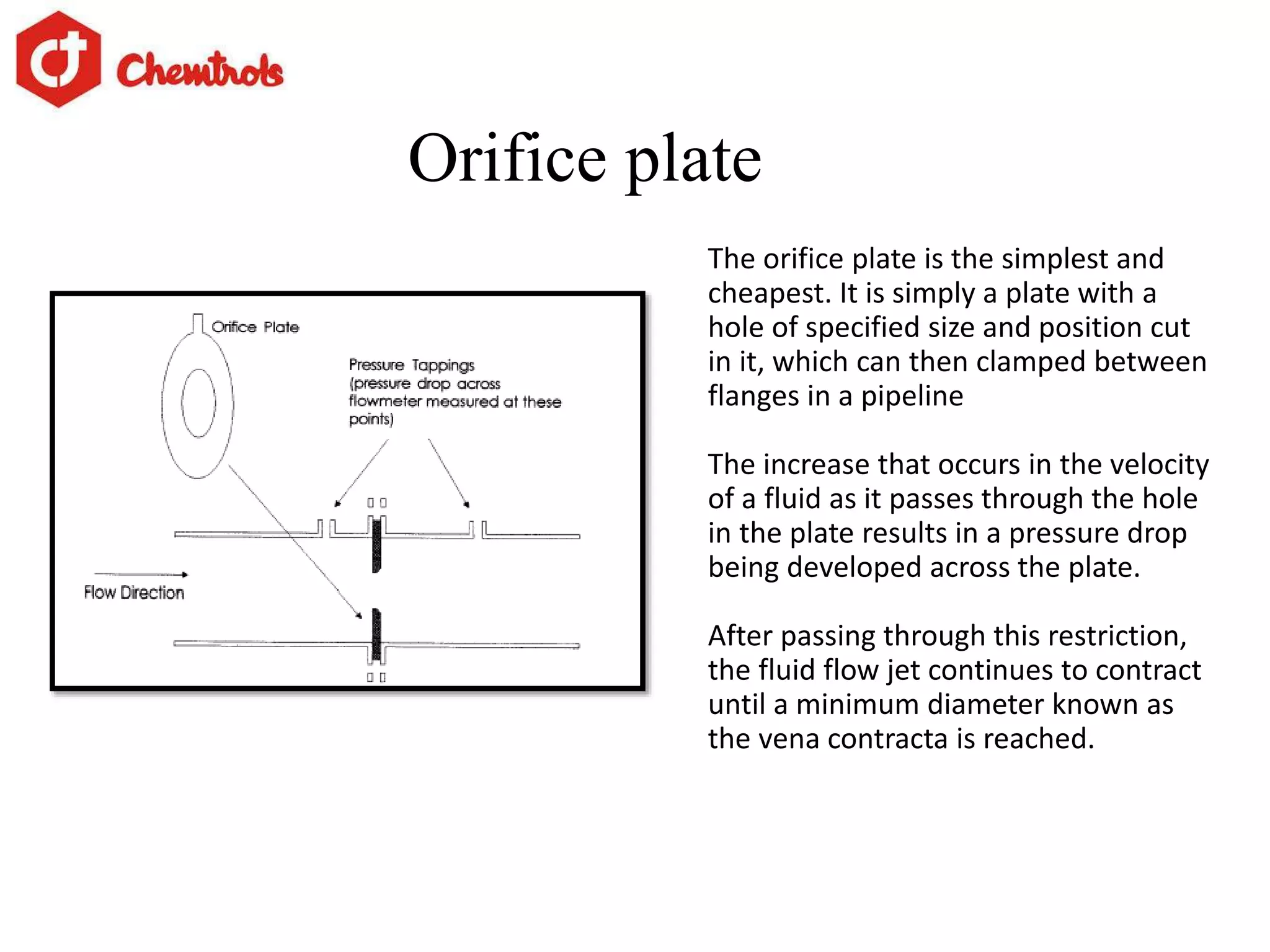
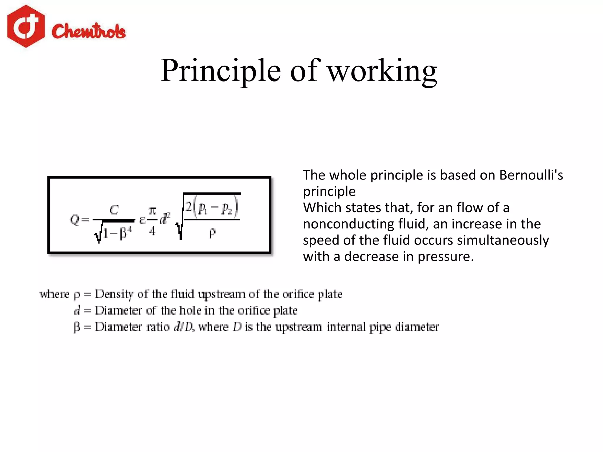
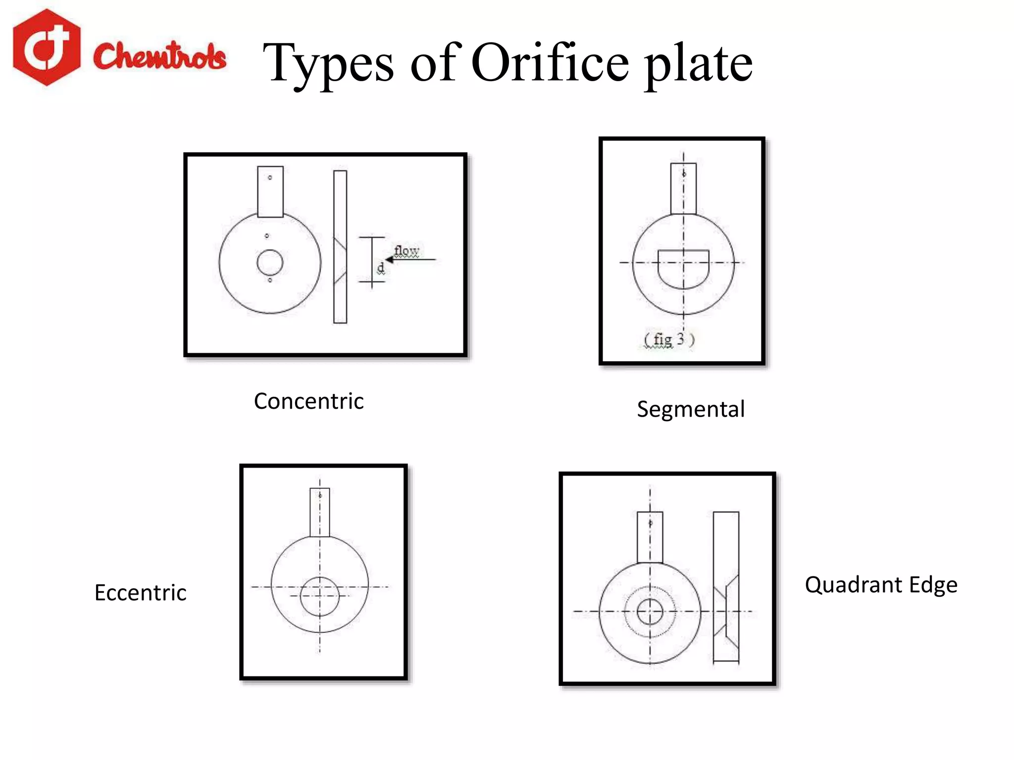
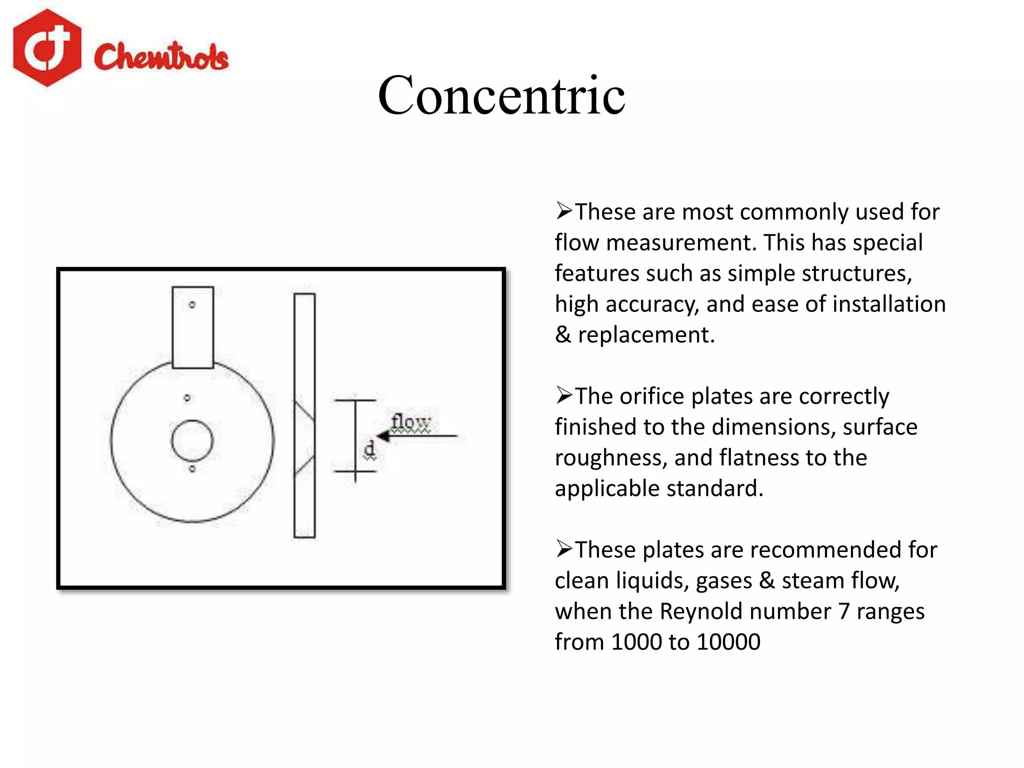
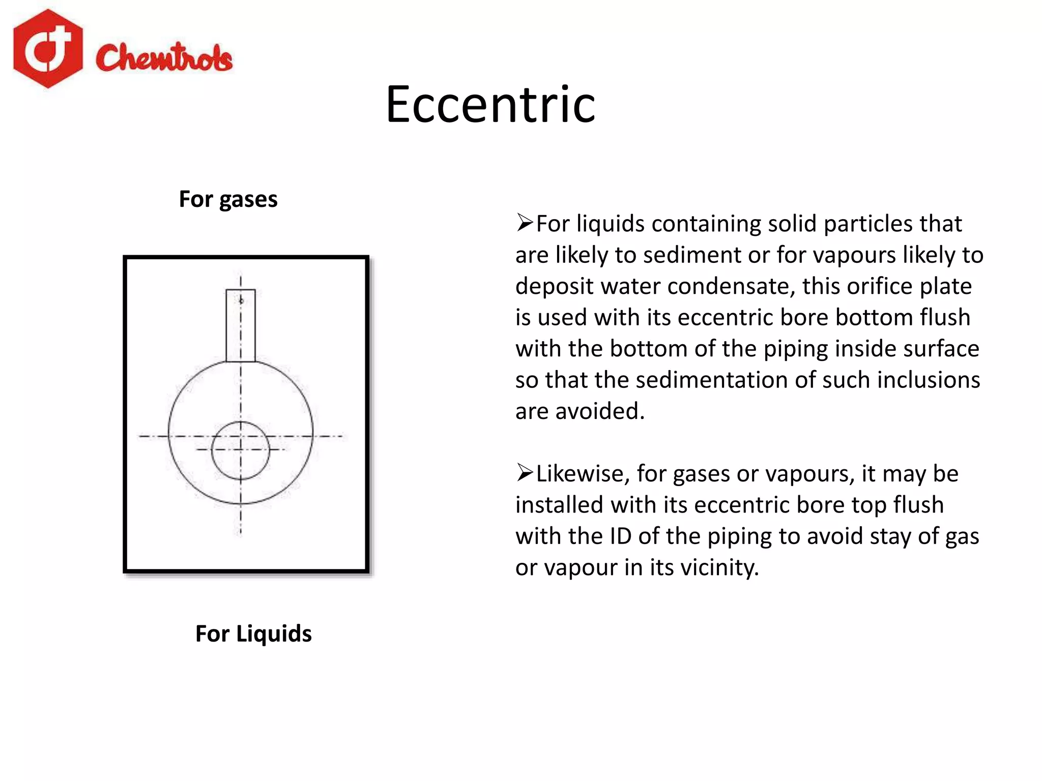


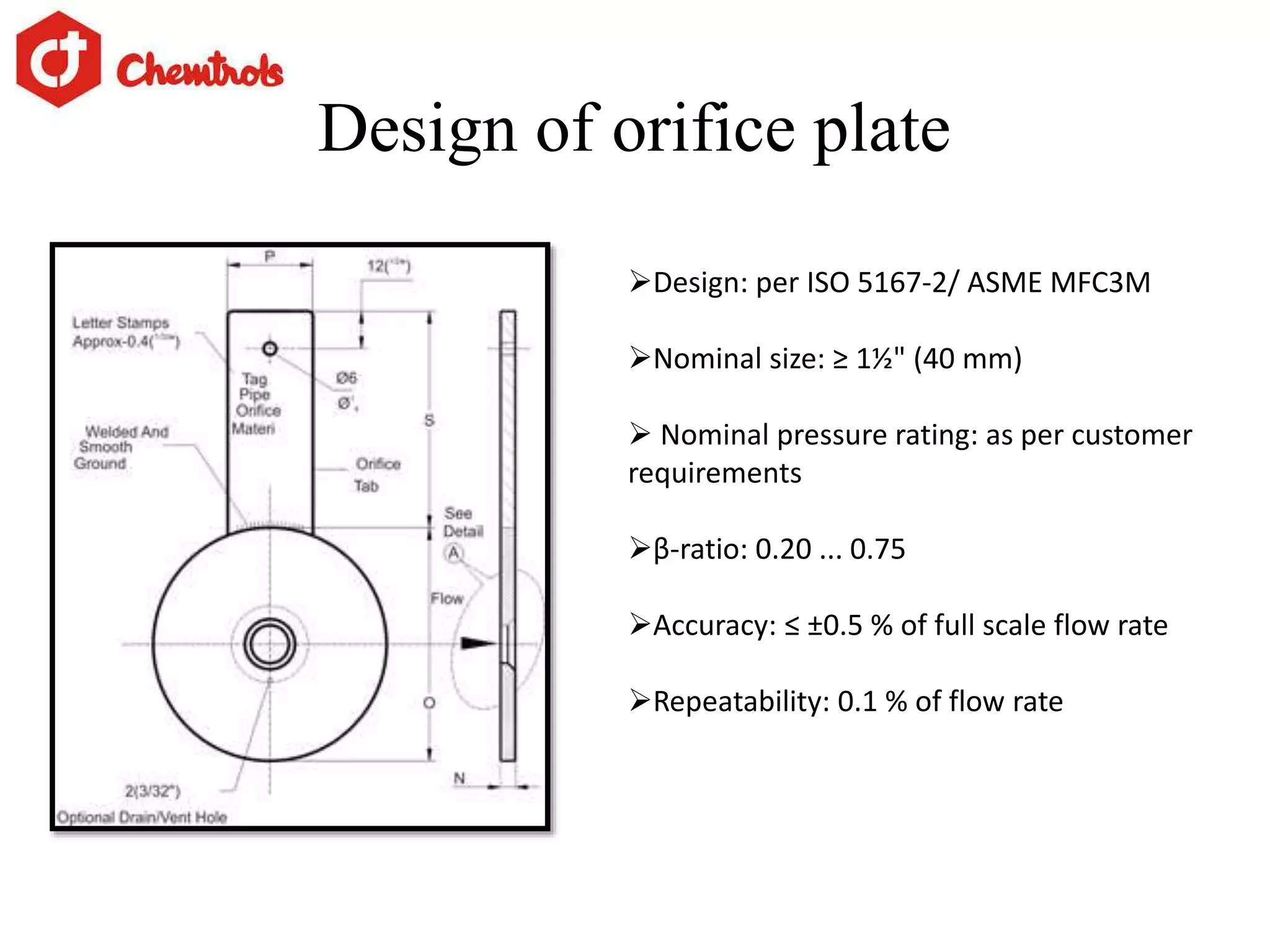
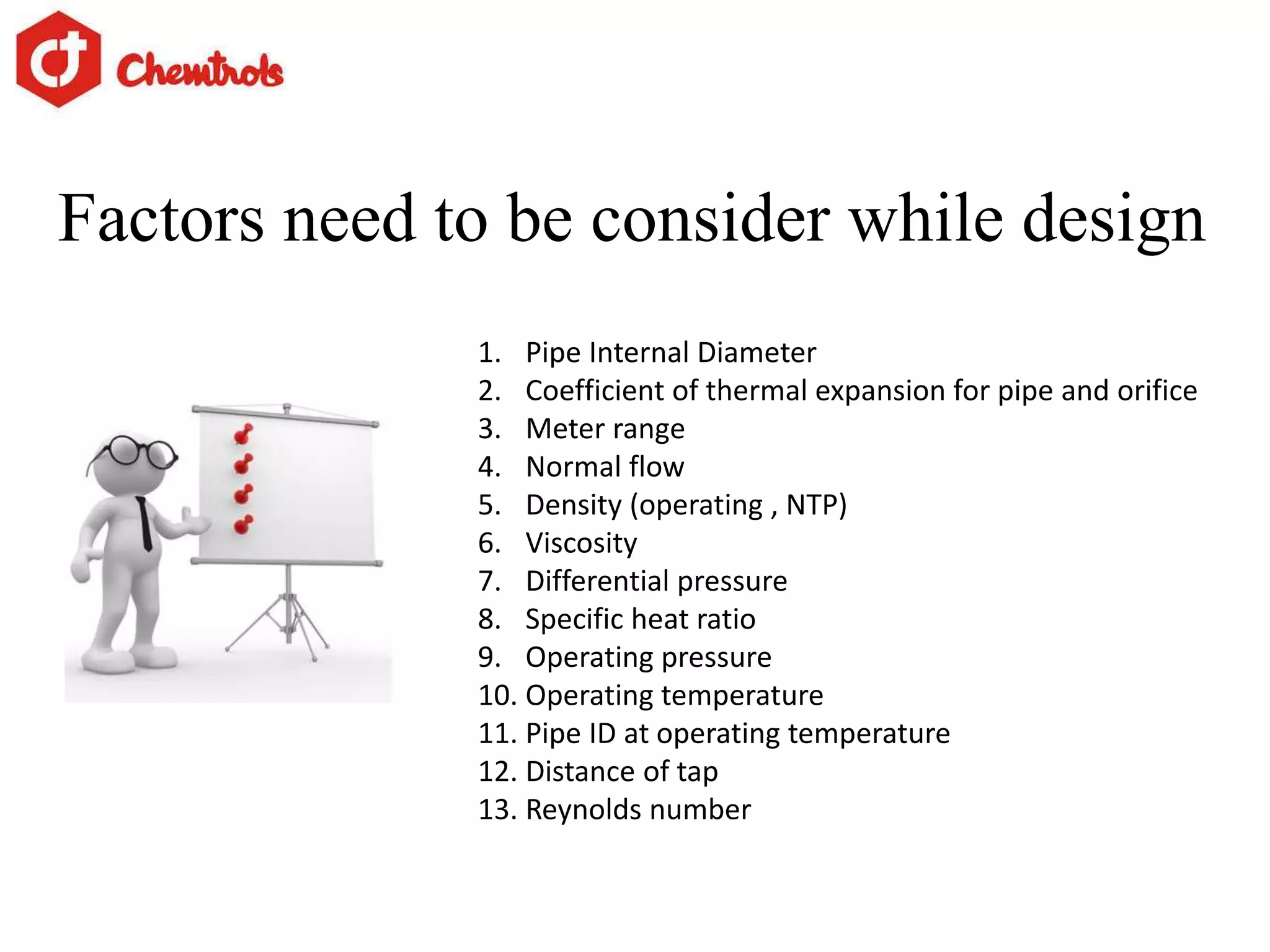


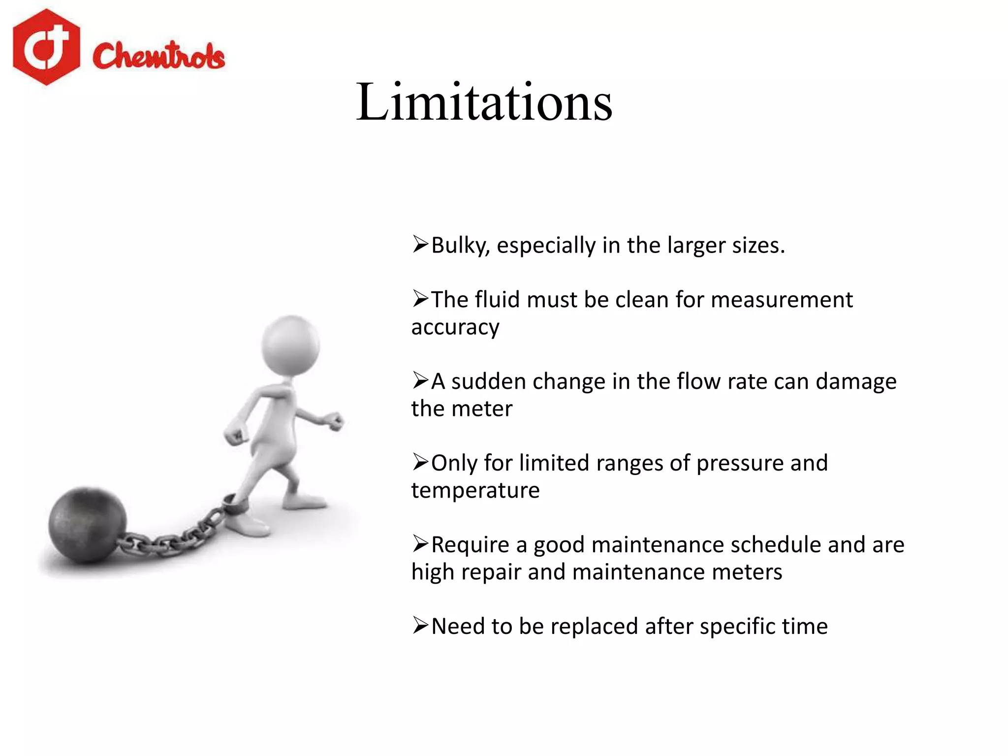


The document summarizes information about orifice plates used for flow measurement. It describes the basic principles of how orifice plates work using Bernoulli's principle to create a pressure drop for measurement. It provides details on different types of orifice plates as well as factors to consider in design. Orifice plates offer benefits of being cheap and reliable but have limitations for clean fluids only and require maintenance. The company discussed provides custom orifice plate solutions and has supplied plates to major oil and gas companies in India.


