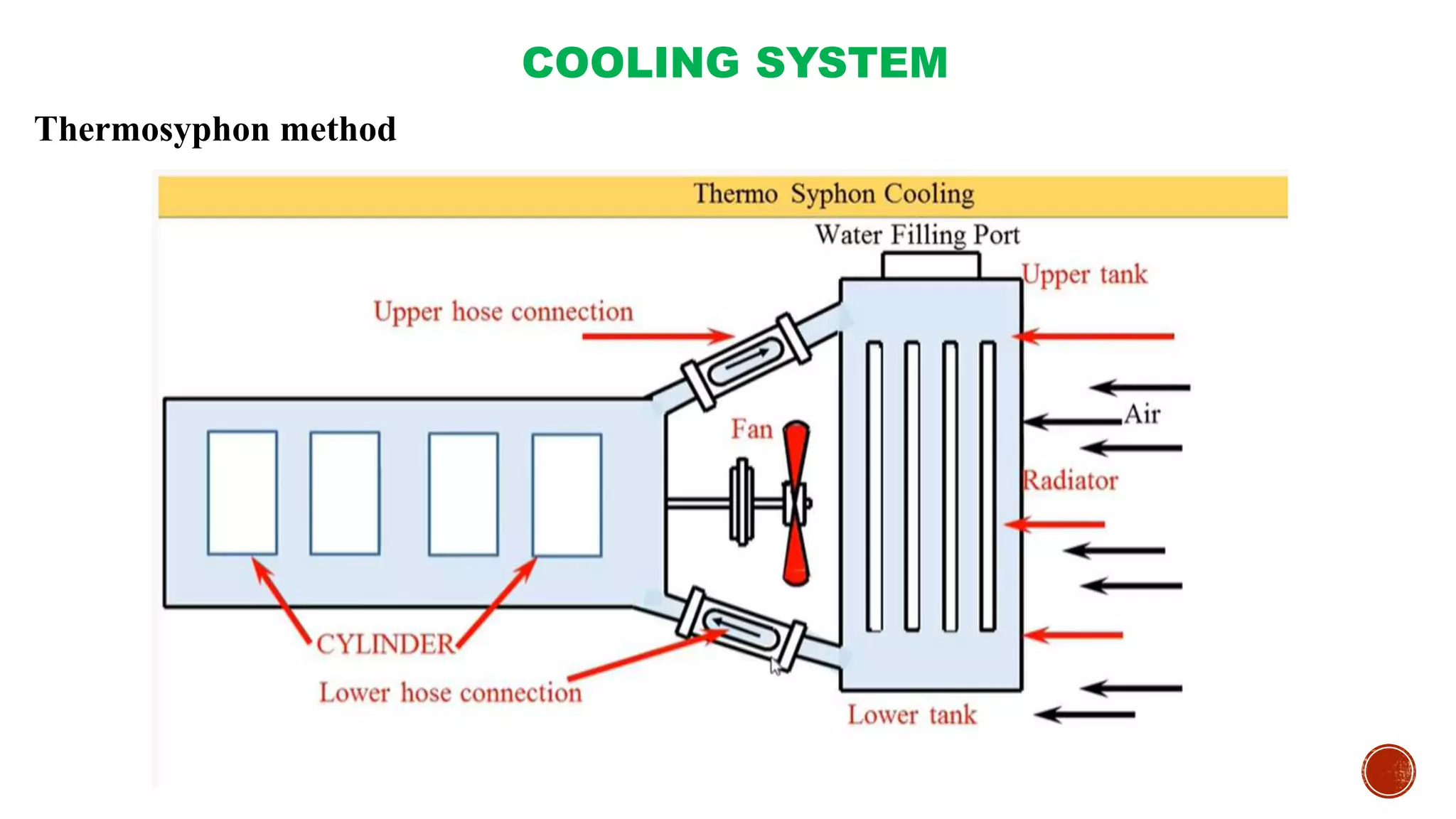
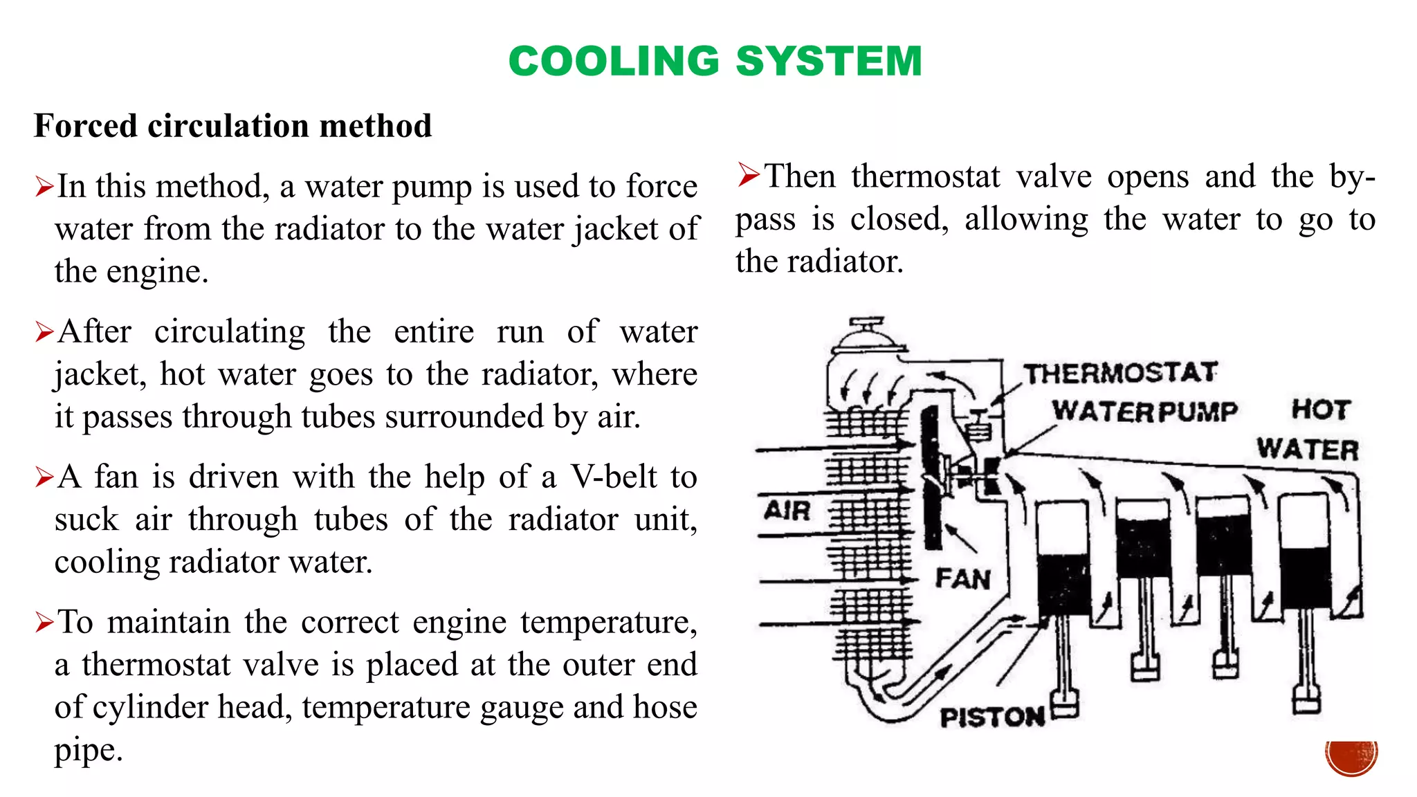
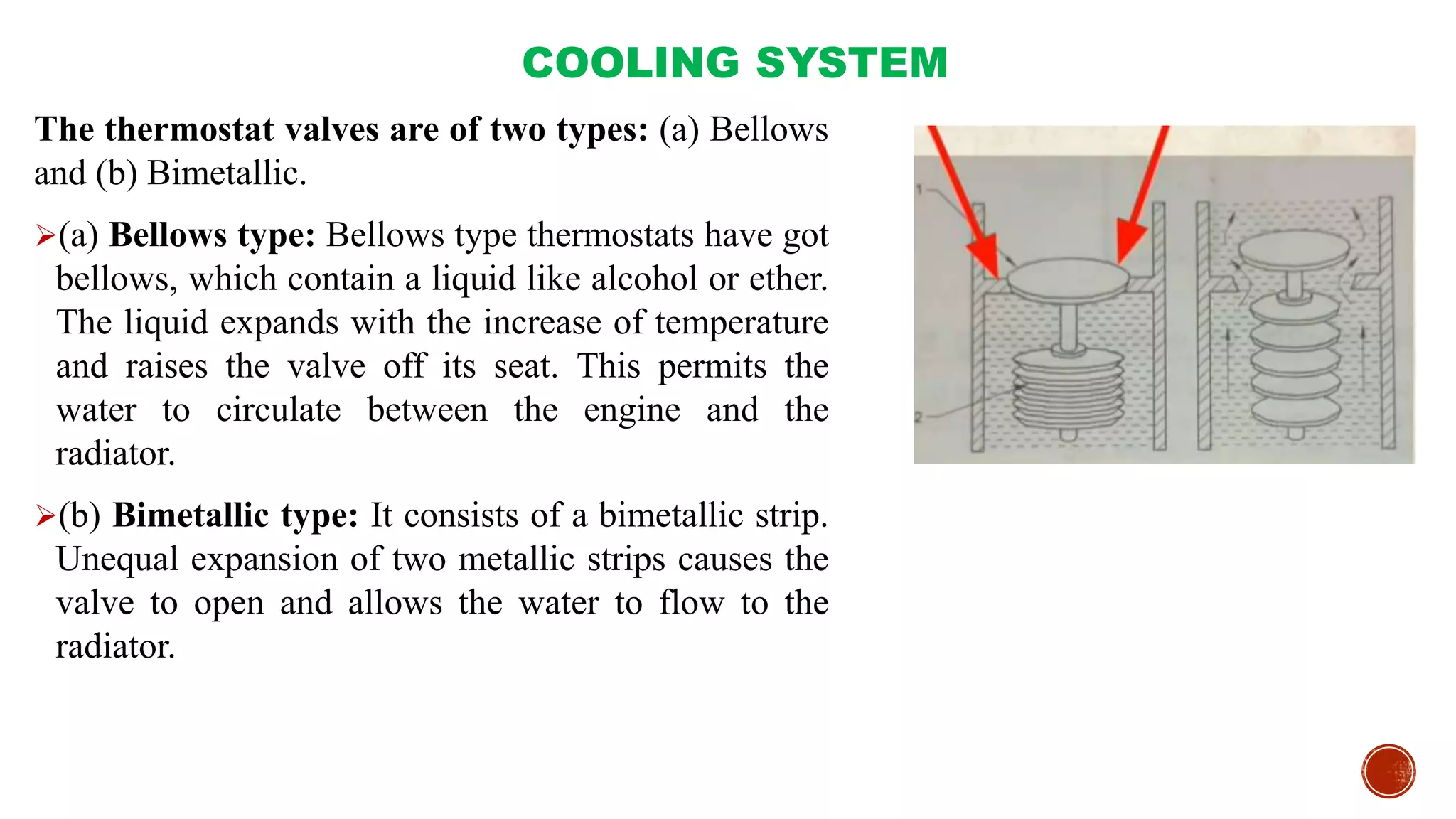
Science 7 - LAND and SEA BREEZE and its Characteristics
Â
SYSTEMS OF IC ENGINE- Cooling System.pptx
1. SYSTEMS OF IC ENGINE:
Cooling System
Dr. Ajay Singh Lodhi
Assistant Professor
College of Agriculture, Balaghat
Jawahar Lal Krishi Vishwa Vidyalaya, Jabalpur (M.P.)
2. COOLING SYSTEM
īFuel is burnt inside the cylinder of an internal combustion engine to produce power. The
temperature produced on the power stroke of an engine can be as high as 1600ÂēC and this
is greater than melting point of engine parts.
īThe cylinder and cylinder head are usually made of cast iron and pistons in most cases are
made of aluminum alloy.
īIt is estimated that about 40 % of total heat produced is passed to the atmosphere via the
exhaust, 30 % is removed by cooling system and only about 30% is used to produce useful
power.
Purpose of cooling
ī(i) To maintain optimum temperature of engine for efficient operation under all conditions.
ī(ii) To dissipate surplus heat for protection of engine components like cylinder, cylinder
head, piston, piston rings and valves.
ī(iii) To maintain the lubricating property of the oil inside the engine cylinder for normal
functioning of the engine.
3. COOLING SYSTEM
Bad effect of high temperature in the engine
ī(i) Cylinder and piston may expand to such an extent that the piston would seize in the
cylinder and stop the engine.
ī(ii) Lubricating quality of the oil inside the cylinder would be destroyed due to high
temperature and there may not be sucking of air in the cylinder.
ī(iii) Pre-ignition of fuel mixture would take place and would cause engine knocking as
well as loss of power.
For satisfactory performance of the engine, neither overheating nor overcooling is desirable.
Experiments have shown that best operating temperature of I.C engine lies between 140ÂēF to
200 ÂēF, depending upon types of engines and load conditions.
4. COOLING SYSTEM
There are two different methods of cooling: (i) air cooling and (ii) water cooling.
Air cooling
īAir cooled engines are those engines, in which heat is conducted from the working
components of the engine to the atmosphere directly. In such engines, cylinders are
generally not grouped in a block.
Principle of air cooling
īThe cylinder of an air cooled engine has fins to increase the area of contact of air for
speedy cooling.
īThe cylinder is normally enclosed in a sheet metal casing called Cowling.
īThe flywheel has blades projecting from its face, so that it acts like a fan drawing air
through a hole in the cowling and directing it around the finned cylinder.
5. COOLING SYSTEM
īFor maintenance of air cooling system, passage of air is kept clean by removing grasses
etc. This is done by removing the cowling and cleaning out the dirt etc. by a stiff brush or
compressed air.
īWhen separate fan is provided, the belt tension is to be checked and adjusted if necessary.
Advantages of air cooling:
īIt is simpler in design and construction.
īWater jackets, radiators, water pump, thermostat, pipes, hoses etc. are not needed.
īIt is more compact. It is comparatively lighter in weight.
Disadvantages:
īThere is uneven cooling of the engine parts.
īEngine temperature is generally high during working period.
6. COOLING SYSTEM
Water cooling
īEngines, using water as cooling medium is called âwater cooled enginesâ.
īThe liquid is circulated round the cylinders to absorb heat from the cylinder walls.
īIn general, water is used as cooling liquid.
īThe heated water is conducted through a radiator which helps in cooling the water.
īThere are three common methods of water cooling:
ī(i) Open jacket or hopper method,
ī(ii) Thermo siphon method, and
ī(iii) Forced circulation method.
7. COOLING SYSTEM
Open jacket or hopper method
īIn this method a hopper or a jacket is provided around the engine cylinder in which the
cooling water or coolant is flowing.
īAs long as the hopper contains water, the engine continues to operate satisfactorily.
īThe hopper is large enough to run for several hours without refilling.
īA drain plug is provided for draining water.
īThis system is not common in present days.
9. COOLING SYSTEM
Thermosyphon method
īIt consists of a radiator, water jacket, fan, temperature gauge and hose connections.
īThe system is based on the principle that heated water which surrounds the cylinder
becomes lighter in weight and it rises up wards in liquid column.
īHot water goes to the radiator, where it passes through tubes surrounded by air.
īCirculation of water takes place due to the density difference between the hot water in the
engine jacket and cold water in the radiator.
īThese two are connected at both sides i.e. at the top and the bottom by using the hose pipe.
īA fan is driven with the help of a V-belt connected to the crankshaft to suck air through
cells of the radiator unit resulting in cooling.
īThe disadvantage of the system is that circulation of water is greatly reduced by
accumulation of scale or foreign matter in the passage and consequently it causes
overheating of the engine.
11. COOLING SYSTEM
Forced circulation method
īIn this method, a water pump is used to force
water from the radiator to the water jacket of
the engine.
īAfter circulating the entire run of water
jacket, hot water goes to the radiator, where
it passes through tubes surrounded by air.
īA fan is driven with the help of a V-belt to
suck air through tubes of the radiator unit,
cooling radiator water.
īTo maintain the correct engine temperature,
a thermostat valve is placed at the outer end
of cylinder head, temperature gauge and hose
pipe.
īThen thermostat valve opens and the by-
pass is closed, allowing the water to go to
the radiator.
12. COOLING SYSTEM
īThe system consists of water pump, radiator, fan, fan-belt, water jacket, thermostat valve,
temperature gauge and hose pipe.
Water pump
īIt is a centrifugal type pump.
īIt has a casing and an impeller, mounted on a shaft.
īThe casing is usually made of cast iron.
īPump shaft is made of some non-corrosive material.
īAt the end of the shaft, a small pulley is fitted which is driven by a V-belt.
īWater pump is mounted at the front end of the cylinder block between the block and the radiator.
ī When the impeller rotates, the water between the impeller blades is thrown outward by
centrifugal force and thus water goes to the cylinder under pressure.
īThe pump outlet is connected by a hose pipe to the bottom of the radiator.
īThe impeller shaft is supported on one or more bearings.
īThere is a seal which prevents leakage of water.
13. COOLING SYSTEM
Radiator
īRadiator is a device for cooling the circulating water in the engine.
īIt holds a large volume of water in close contact with a large volume of air so that heat is
transferred from the water to the air easily.
īHot water flows into the radiator at the top and cold water flows out from the bottom.
ī Tubes or passages carry the water from the top of the radiator to the bottom, passing it over
a large metal surface.
īAir flows between the tubes or through the cells at right angles to the downward flowing
water.
īThis helps in transferring the heat from the water to the atmosphere.
14. COOLING SYSTEM
īOn the basis of fabrication, the radiator is of two types: tubular type and cellular type
Tubular type radiator:
īIt has round or flat water tubes, leading from the top to the bottom of the radiator.
īThey may be soldered, brazed or welded in place or fastened by means of a stuffing box at
each end.
īFins or folded strips of light sheet metal, placed between the tubes, increase the radiating
surface and improve the heat transfer.
Cellular type radiator:
īIt has a core made of short air tubes which are laid horizontally and soldered together at the
ends with space between them to allow water to flow.
īIt is also called Honey comb type radiator.
15. COOLING SYSTEM
Thermostat valve
īIt is a control valve, used in the cooling system to control the flow of water when activated
by a temperature signal.
īIt is a special type of valve, which closes the inlet passage of the water connected to the
radiator.
īThe thermostat is placed in the water passage between the cylinder head and the top of
radiator.
īIts purpose is to close this passage when the engine is cold, so that water circulation is
restricted, causing the engine to reach operating temperature more quickly.
īThermostats are designed to start opening at 70ÂēC to 75 ÂēC and then fully open at 82 ÂēC for
petrol engine and 88-90 ÂēC for diesel engine.
16. COOLING SYSTEM
The thermostat valves are of two types: (a) Bellows
and (b) Bimetallic.
ī(a) Bellows type: Bellows type thermostats have got
bellows, which contain a liquid like alcohol or ether.
The liquid expands with the increase of temperature
and raises the valve off its seat. This permits the
water to circulate between the engine and the
radiator.
ī(b) Bimetallic type: It consists of a bimetallic strip.
Unequal expansion of two metallic strips causes the
valve to open and allows the water to flow to the
radiator.
17. COOLING SYSTEM
īWater jackets: Water jackets are cored out around the engine cylinder so that water can
circulate freely around the cylinder as well as around the valve opening.
īFan: The fan is usually mounted on the water pump shaft. It is driven by the same belt
that drives the pump and the dynamo. The purpose of the fan is to provide strong draft of
air through the radiator to improve engine cooling.