SlideShare a Scribd company logo
1 of 73
Download to read offline
Chapter 7:
Flow measurements
Prepared by:
Er.Binu Karki
M.sc. iWRM 1
Flow through Orifice
• What is a Orifice?
Orifice is a small opening of any cross-section(circular,
triangular, rectangular etc.) on the side or bottom of the
tank through which fluid is flowing.
2
Flow through Orifice
What is a mouthpiece?
A mouthpiece is a short pipe
of length two or three times its
diameter fitted in a tank/vessel
containing fluid.
Both of them are used for
measuring the rate of flow of
fluid.
3
Vena-contracta
4
• The liquid coming out from an
orifice forms a jet of liquid whose
cross-sectional area is less than
that of orifice.
• The area of jet of fluid goes on
decreasing and at a section ,it
becomes minimum.
• This section is approximately at a
distance of half of diameter of
orifice.
• Beyond this section the jet
diverges and is attracted to
downward direction by gravity.
This section is called Vena-contracta.
Derivation of theoretical velocity
at vena-contracta
5
Consider two points 1 and 2 as
shown in figure.
Point 1 is inside the tank and point 2
is at vena-contracta.
Let the flow is steady and at
constant head H.
Applying Bernoullis equation at point
1 and 2,
Derivation of theoretical velocity
at vena-contracta
6
Hydraulic coefficients
The Hydraulic co-efficients are
1.Coefficient of velocity, Cv
2.Coefficient of contraction, Cc
3.Coefficient of discharge, Cd
•Coefficient of Velocity(Cv)
It is defined as the ratio between the actual velocity of a jet of liquid at
vena-contracta and the theoretical velocity of the jet.
The value of Cv varies from 0.95 to 0.99 for different orifices depending
on their shape ,size and on the head under which flow takes place.
Generally 0.98 is taken as its value for sharp edged orifice.
7
Hydraulic coefficients
• Coefficient of Contraction(Cc)
It is defined as the ratio of the area of the jet at vena-
contracta to the area of the total opening. Its value varies
from 0.61 to 0.69.Generally 0.64 can be taken as value of
Cc.
8
Hydraulic coefficients
• Coefficient of discharge(Cd)
It is defined as the ratio of actual discharge to the
theoretical discharge from any opening. Its value lies
between 0.61 to 0.65.Generally 0.62 is taken as its value.
9
Experimental determination of
hydraulic coefficients
10
Determination of Coefficient of discharge(Cd)
The water is allowed to flow through an orifice fitted to a tank under
constant head H.
The water is collected in a measuring tank for known time t.The height
of water in the measuring tank is noted down.
Experimental determination of
hydraulic coefficients
11
• .Actual discharge through the orifice,
Experimental determination of
hydraulic coefficients
12
Determination of Coefficient of velocity(Cv)
Let C-C represent vena contracta of jet of water coming out from an
orifice under constant head H. Consider a liquid particle which is at vena
contracta at any time and takes position P along the jet in time t.
Experimental determination of
hydraulic coefficients
13
Experimental determination of
hydraulic coefficients
14
Experimental determination of
hydraulic coefficients
15
Determination of Coefficient of contraction(Cc)
We can determine the coefficient of contraction from the
following equations:
Classification of Orifice
Depending on size and head of liquid from center of orifice
 Small orifice: If the head of liquid from center of orifice >5 times
depth of orifice
 Large orifice: If the head of liquid from center of orifice <5 times
depth of orifice
Depending on their cross-sectional area
• Circular, Triangular, Rectangular and Square
Depending on shape of u/s edge of orifice
• Sharp edged orifice
• Bell mouthed orifice
Depending on nature of discharge
• Free discharging orifice
• Fully Drowned/submerged orifice
• Partially Drowned/submerged orifice
16
Depending on shape of
u/s edge of orifice
17
Depending on nature
of discharge
18
Flow through small orifice
• In case of small orifice, the velocity in the entire cross-
section of the jet is considered to be constant and
discharge is calculated by
19
Flow through large rectangular
orifice
• Consider a large rectangular orifice in one side of the
tank discharging freely into atmoshphere under constant
head H as shown in figure.
20
Flow through large rectangular
orifice
Let,H1 =height of liquid above top edge of the orifice
H2 =height of liquid above bottom edge of the orifice
b =breadth of orifice
d= depth of orifice=H2 –H1
Cd = Coefficient of discharge
Consider an elementary horizontal strip of depth dh at a depth h below the free
surface of the liquid in the tank as shown in figure.
Area of strip=b*dh
21
Flow through large rectangular
orifice
22
Flow through totally submerged
orifice
23
Flow through totally submerged
orifice
24
Flow through totally submerged
orifice
25
Flow through partially
submerged orifice
26
Flow through partially
submerged orifice
27
Video!!
28
Flow measurement Device :
Venturimeter
A venturimeter is a device used for measuring the rate of flow of fluid flowing
throught the pipe.It consists of three parts.
1.A short converging part
2.Throat
3.Diverging part
It is based on the principle of Bernoullis equation.
29
Expression for rate of flow
through Venturimeter
30
Expression for rate of flow
through Venturimeter
31
Expression for rate of flow
through Venturimeter
32
Manometer connected to
Venturi-meter
33
Expression for rate of flow
through Venturimeter
34
Flow measurement Device:
Orifice meter/Orifice Plate
• It is a device used for measuring rate of flow of fluid through a pipe.
• It is cheaper in comparison to venturimeter but it works on same principle as
venturimeter.
• It consists of a flat circular plate which has a circular sharp edged hole
called orifice which is concentric with the pipe.
• The orifice diameter is generally kept 0.5 times the diameter of
pipe.(normally 0.4-0.8 times pipe diameter can be used)
• A differential manometer is connected at a distance(1.5-2 times pipe dia)in
u/s and (0.5 times orifice dia)distance in d/s from orifice plate.
35
Flow measurement Device:
Orifice meter/Orifice Plate
36
Expression for rate of flow
through Orifice plate/meter
37
Expression for rate of flow
through Orifice plate/meter
38
Expression for rate of flow
through Orifice plate/meter
39
• For Orifice meter,
Q=
Where,
Cd= Coefficient of discharge for orifice meter
The Cd value of orifice meter is much smaller than that for
venturimeter.
Flow measurement Device:
Pitot tube
40
• It is a device used for measuring the velocity of flow at any point in a
pipe/channel.
• It is based on the principle that
“When velocity of flow at a point becomes zero, the pressure there is
increased due to conversion of kinetic energy into pressure energy”
• The common type of pitot tube consists of a glass tube bent at right
angles.
Flow measurement Device:
Pitot tube
41
• In fig, the lower end is bent through
90
ₒ
upwards
• The liquid rises up in it due to
conversion of kinetic energy into
pressure energy.
• The velocity is measured by
measuring the rise of liquid in the
tube.
Flow measurement Device:
Pitot tube
42
Flow measurement Device:
Pitot tube
43
Flow measurement Device:
Nozzle meter
44
• It is used to measure discharge through the pipes.
• Nozzle meter is similar to venturimeter with its divergent part omitted
so the basic equations are same.
• Its coefficient of discharge is same as that of venturimeter.
Notches and Weirs
45
Notch
• A notch is a device used for measuring the rate of flow of liquid
through a small channel or a tank.
• It may be defined as a opening in the side of the tank or small
channel in such a way that the liquid surface in the tank/channel is
below top edge of the opening.
• Notch is generally made of metallic plate.
Notches and Weirs
46
Weir
• A Weir is a concrete/ masonry structure placed in an open channel
over which flow occurs.
• It is generally in the form of vertical wall, with the sharp edge at the
top, running all the way across the open channel.
• Weir is of big size in comparison to notch.
Notches and Weirs
47
Classification of notches and weirs
Notches and Weirs
48
Classification of notches and weirs
Notches and Weirs
49
Discharge over rectangular notches and weirs
Some terms:
Nappe/Vein: The sheet of water flowing through the notch or weir
Crest/Sill: The bottom edge of notch or top of weir over which water flows
Notches and Weirs
50
Discharge over rectangular notches and weirs
Velocity of Approach
It is the velocity with which the water approaches or reaches the
weir/notch before it flows over it.
• If Va =velocity of approach
Then,
ha=additional head equal to Va2/2g due to velocity of approach acting
on water flowing over the notch.
H+ha=initial height over the notch
ha= final height over the notch
51
Velocity of Approach
Process of determining Va:
•Find discharge ‘Q’ over notch/weir neglecting the Va.
•Divide Q by cross-sectional area of channel on the u/s side of
weir/notch to find Va.
•Find additional head ha.
•Calculate discharge again including Va.
52
Notches and Weirs
53
Discharge over triangular notches and weirs
Notches and Weirs
54
Discharge over triangular notches and weirs
Notches and Weirs
55
Discharge over triangular notches and weirs
Notches and Weirs
56
Discharge over triangular notches and weirs
If Va is taken into account,
Then ha=additional head of water flowing over the weir/notch
Or ha = Va2/2g
The discharge Q over triangular notch/weir may be modified as,
Notches and Weirs
57
Advantages of triangular notches/weirs over
rectangular notch/weir
Triangular notch/weir is preferred because:
1.The expression for discharge for a right angled V-notch/weir is very
simple.
2.Triangular notch gives accurate results while measuring low
discharge in comparison to rectangular notch/weir.
3.Only one reading of H is required for computation of discharge in
case of triangular notch.
4.Ventilation of triangular notch is not necessary.
Notches and Weirs
58
Discharge over trapezoidal notches and weirs
A trapezoidal notch/weir is a combination of rectangular and triangular
notch/weir.
Thus the total discharge =discharge through a rectangular weir/notch +
discharge through a triangular notch/weir.
Let,
H=height of water over the notch.
L=length of the crest of the notch.
Cd1=Coefficient of discharge through rectangular portion ABCD
Cd2=coefficient of discharge for triangular portion(FAD and BCE)
Notches and Weirs
59
Discharge over trapezoidal notches and weirs
Notches and Weirs
60
Discharge over Cippoletti notches and weirs
• Cipolletti weir is trapezoidal weir having side slopes of 1 horizontal
to 4 vertical
• By providing slopes on sides , an increase in discharge through the
triangular portion ABC and DEF is obtained.
Notches and Weirs
61
Discharge over stepped notches and weirs
Emptying and filling of reservoir
without inflow :
rectangular/Cylindrical tank
62Cylindrical/Rectangular tank
Conical tank
Emptying and filling of reservoir
without inflow:rectangular tank
63
Consider,
H1=height of liquid above the center of
the orifice provided on side/bottom of the
tank
t= time required for liquid to fall from H1
to H2 above the center of opening
Let at any instant ,
h= height of liquid above orifice at an
instant
Let the liquid surface fall by small amount
dh in time dt.
A=horizontal cross-sectional of the tank
Q= discharge through the orifice
Volume of liquid discharged during time
dt is Qdt.
Emptying and filling of reservoir
without inflow:rectangular tank
64
As the volume of liquid leaving the tank is equal to the volume of liquid
flowing through the orifice/mouthpiece during the same interval of time.
we have,
A(-dh)=Qdt (negative sign because as time increases head decreases)
If a=cross-sectional area of orifice/mouthpiece and
Cd=coefficient of discharge then,
Emptying and filling of reservoir
without inflow :rectangular tank
65
Emptying and filling of reservoir
without inflow:rectangular tank
66
If the tank is completely emptied then H2 =0 becomes
Emptying and filling of reservoir without
inflow: conical tank
67
Emptying and filling of reservoir
without inflow:conical tank
68
Emptying and filling of reservoir
without inflow:conical tank
69
Emptying and filling of reservoir
with inflow: rectangular tank
70
Consider,
A=cross-sectional area of tank
a= cross-sectional area of orifice/mouthpiece
Q=constant inflow of liquid which is also
discharging through orifice
t= time in which liquid level changes from H1
to H2 above the center of the orifice
dt = time required to increase the water level
by dh.
q= discharge through the orifice
Volume of liquid added to the tank=Adh
In time dt the volume of inflow in tank=Qdt
Volume of outflow through the orifice=qdt
Emptying and filling of reservoir
with inflow: rectangular tank
71
Emptying and filling of reservoir
with inflow: rectangular tank
72
Emptying and filling of reservoir
with inflow: rectangular tank
73

More Related Content

What's hot

Fluid mechanics - Problems on Orificemeter and Inclined Venturimeter
Fluid mechanics - Problems on Orificemeter and Inclined VenturimeterFluid mechanics - Problems on Orificemeter and Inclined Venturimeter
Fluid mechanics - Problems on Orificemeter and Inclined VenturimeterAmos David
 
Flow through orifice meter
Flow through orifice meterFlow through orifice meter
Flow through orifice meterPulkit Shukla
 
Stability of Submerged Bodies in Fluid
Stability of Submerged Bodies in FluidStability of Submerged Bodies in Fluid
Stability of Submerged Bodies in FluidAnkit Singhal
 
Kinematics of fluid flow & it’s application.
Kinematics of fluid flow & it’s application.Kinematics of fluid flow & it’s application.
Kinematics of fluid flow & it’s application.NIKHIL PAKWANNE
 
Mechanical pressure gauges
Mechanical pressure gaugesMechanical pressure gauges
Mechanical pressure gaugesssuser03e697
 
Fluid mechanics Lab Report
Fluid mechanics Lab ReportFluid mechanics Lab Report
Fluid mechanics Lab ReportMuhammad Bilal
 
Separation of boundary layer
Separation of boundary layerSeparation of boundary layer
Separation of boundary layerYash Patel
 
fluid flow measuring instruments
fluid flow measuring instrumentsfluid flow measuring instruments
fluid flow measuring instrumentsGaurav Dave
 
Presentation on notches and weirs
Presentation on notches and weirsPresentation on notches and weirs
Presentation on notches and weirssush_vyas
 
Dimensionless analysis & Similarities
Dimensionless analysis & Similarities Dimensionless analysis & Similarities
Dimensionless analysis & Similarities sajan gohel
 
Unsymmetrical bending.ppt
Unsymmetrical bending.pptUnsymmetrical bending.ppt
Unsymmetrical bending.pptVenkatesh Ca
 

What's hot (20)

Flow measurement
Flow measurementFlow measurement
Flow measurement
 
Flow through pipes ppt
Flow through pipes pptFlow through pipes ppt
Flow through pipes ppt
 
Fluid mechanics - Problems on Orificemeter and Inclined Venturimeter
Fluid mechanics - Problems on Orificemeter and Inclined VenturimeterFluid mechanics - Problems on Orificemeter and Inclined Venturimeter
Fluid mechanics - Problems on Orificemeter and Inclined Venturimeter
 
Flow through pipes
Flow through pipesFlow through pipes
Flow through pipes
 
Flow through orifice meter
Flow through orifice meterFlow through orifice meter
Flow through orifice meter
 
PRESSURE & HEAD (PART-1)
PRESSURE & HEAD (PART-1)PRESSURE & HEAD (PART-1)
PRESSURE & HEAD (PART-1)
 
Stability of Submerged Bodies in Fluid
Stability of Submerged Bodies in FluidStability of Submerged Bodies in Fluid
Stability of Submerged Bodies in Fluid
 
Kinematics of fluid flow & it’s application.
Kinematics of fluid flow & it’s application.Kinematics of fluid flow & it’s application.
Kinematics of fluid flow & it’s application.
 
Impact of jet
Impact of jetImpact of jet
Impact of jet
 
Bernoulli Theorem
Bernoulli  TheoremBernoulli  Theorem
Bernoulli Theorem
 
Pelton wheel
Pelton wheel Pelton wheel
Pelton wheel
 
Francis Turbine
Francis Turbine Francis Turbine
Francis Turbine
 
Mechanical pressure gauges
Mechanical pressure gaugesMechanical pressure gauges
Mechanical pressure gauges
 
Fluid mechanics Lab Report
Fluid mechanics Lab ReportFluid mechanics Lab Report
Fluid mechanics Lab Report
 
Separation of boundary layer
Separation of boundary layerSeparation of boundary layer
Separation of boundary layer
 
fluid flow measuring instruments
fluid flow measuring instrumentsfluid flow measuring instruments
fluid flow measuring instruments
 
Presentation on notches and weirs
Presentation on notches and weirsPresentation on notches and weirs
Presentation on notches and weirs
 
Dimensionless analysis & Similarities
Dimensionless analysis & Similarities Dimensionless analysis & Similarities
Dimensionless analysis & Similarities
 
Unsymmetrical bending.ppt
Unsymmetrical bending.pptUnsymmetrical bending.ppt
Unsymmetrical bending.ppt
 
Fluid Kinematics
Fluid KinematicsFluid Kinematics
Fluid Kinematics
 

Similar to 080118 chapter 7 flow measurements

Estimate coefficient of discharge for rectangular and V notches weirs
Estimate coefficient of discharge for rectangular and V notches weirsEstimate coefficient of discharge for rectangular and V notches weirs
Estimate coefficient of discharge for rectangular and V notches weirsNabeel Afzal
 
flowmeasurement-ppt modified.pptx
flowmeasurement-ppt modified.pptxflowmeasurement-ppt modified.pptx
flowmeasurement-ppt modified.pptxSunanthini Rajkumar
 
LECTURE 5 FLUID FLOW MEASUREMENT.pptx
LECTURE 5 FLUID FLOW MEASUREMENT.pptxLECTURE 5 FLUID FLOW MEASUREMENT.pptx
LECTURE 5 FLUID FLOW MEASUREMENT.pptxVanJasperCastillo
 
Principles of Fluid Flow Measurement.pdf
Principles of Fluid Flow Measurement.pdfPrinciples of Fluid Flow Measurement.pdf
Principles of Fluid Flow Measurement.pdfonwukwe
 
Flow Measurnment
Flow MeasurnmentFlow Measurnment
Flow MeasurnmentParth Patel
 
Lect. 11 water measure ppt. 2021 Final.pptx
Lect.  11  water measure ppt. 2021 Final.pptxLect.  11  water measure ppt. 2021 Final.pptx
Lect. 11 water measure ppt. 2021 Final.pptxfabmovieKhatri
 
Types orifice and mouthpiece
Types orifice and mouthpieceTypes orifice and mouthpiece
Types orifice and mouthpiecetirath prajapati
 
ORIFICES AND MOUTHPIECES
ORIFICES AND MOUTHPIECESORIFICES AND MOUTHPIECES
ORIFICES AND MOUTHPIECESHome
 
88c40e_Suppressed Weir Lecture.pptx
88c40e_Suppressed Weir Lecture.pptx88c40e_Suppressed Weir Lecture.pptx
88c40e_Suppressed Weir Lecture.pptxWaliEdwardian1
 
Variable Headmeter
Variable HeadmeterVariable Headmeter
Variable HeadmeterShivang258
 
Application of Fluid Mechanics in Agriculture
Application of Fluid Mechanics in AgricultureApplication of Fluid Mechanics in Agriculture
Application of Fluid Mechanics in AgricultureSaravanaKumaran17
 
Ch6_Flow Measurements.pdf
Ch6_Flow Measurements.pdfCh6_Flow Measurements.pdf
Ch6_Flow Measurements.pdfVamshi962726
 
Application of bernoulli's equation
Application of bernoulli's equationApplication of bernoulli's equation
Application of bernoulli's equationDarshil Vekaria
 
12 Flow measurement.ppt
12 Flow measurement.ppt12 Flow measurement.ppt
12 Flow measurement.pptMoazamAmin
 
orifice meter and its application_ppt
orifice meter and its application_pptorifice meter and its application_ppt
orifice meter and its application_pptKrishna Peshivadiya
 
Measurement of discharge in channels & Design of lined canal
Measurement of discharge in channels & Design of lined canalMeasurement of discharge in channels & Design of lined canal
Measurement of discharge in channels & Design of lined canalJaswinder Singh
 
Irrigation Wter Measurement and Water Conveyance Systems
Irrigation Wter Measurement and Water Conveyance SystemsIrrigation Wter Measurement and Water Conveyance Systems
Irrigation Wter Measurement and Water Conveyance SystemsMd Irfan Ansari
 

Similar to 080118 chapter 7 flow measurements (20)

Estimate coefficient of discharge for rectangular and V notches weirs
Estimate coefficient of discharge for rectangular and V notches weirsEstimate coefficient of discharge for rectangular and V notches weirs
Estimate coefficient of discharge for rectangular and V notches weirs
 
flowmeasurement-ppt modified.pptx
flowmeasurement-ppt modified.pptxflowmeasurement-ppt modified.pptx
flowmeasurement-ppt modified.pptx
 
LECTURE 5 FLUID FLOW MEASUREMENT.pptx
LECTURE 5 FLUID FLOW MEASUREMENT.pptxLECTURE 5 FLUID FLOW MEASUREMENT.pptx
LECTURE 5 FLUID FLOW MEASUREMENT.pptx
 
Principles of Fluid Flow Measurement.pdf
Principles of Fluid Flow Measurement.pdfPrinciples of Fluid Flow Measurement.pdf
Principles of Fluid Flow Measurement.pdf
 
Flow Measurnment
Flow MeasurnmentFlow Measurnment
Flow Measurnment
 
Lect. 11 water measure ppt. 2021 Final.pptx
Lect.  11  water measure ppt. 2021 Final.pptxLect.  11  water measure ppt. 2021 Final.pptx
Lect. 11 water measure ppt. 2021 Final.pptx
 
Types orifice and mouthpiece
Types orifice and mouthpieceTypes orifice and mouthpiece
Types orifice and mouthpiece
 
ORIFICES AND MOUTHPIECES
ORIFICES AND MOUTHPIECESORIFICES AND MOUTHPIECES
ORIFICES AND MOUTHPIECES
 
88c40e_Suppressed Weir Lecture.pptx
88c40e_Suppressed Weir Lecture.pptx88c40e_Suppressed Weir Lecture.pptx
88c40e_Suppressed Weir Lecture.pptx
 
Variable Headmeter
Variable HeadmeterVariable Headmeter
Variable Headmeter
 
Application of Fluid Mechanics in Agriculture
Application of Fluid Mechanics in AgricultureApplication of Fluid Mechanics in Agriculture
Application of Fluid Mechanics in Agriculture
 
Ch6_Flow Measurements.pdf
Ch6_Flow Measurements.pdfCh6_Flow Measurements.pdf
Ch6_Flow Measurements.pdf
 
Application of bernoulli's equation
Application of bernoulli's equationApplication of bernoulli's equation
Application of bernoulli's equation
 
12 Flow measurement.ppt
12 Flow measurement.ppt12 Flow measurement.ppt
12 Flow measurement.ppt
 
orifice meter and its application_ppt
orifice meter and its application_pptorifice meter and its application_ppt
orifice meter and its application_ppt
 
Weirs
WeirsWeirs
Weirs
 
venturi meter
venturi meterventuri meter
venturi meter
 
Measurement of discharge in channels & Design of lined canal
Measurement of discharge in channels & Design of lined canalMeasurement of discharge in channels & Design of lined canal
Measurement of discharge in channels & Design of lined canal
 
Irrigation Wter Measurement and Water Conveyance Systems
Irrigation Wter Measurement and Water Conveyance SystemsIrrigation Wter Measurement and Water Conveyance Systems
Irrigation Wter Measurement and Water Conveyance Systems
 
Orifice and mouthpieces
Orifice and mouthpieces Orifice and mouthpieces
Orifice and mouthpieces
 

More from Binu Karki

260118 chapter 6 fluid dynamics
260118 chapter 6 fluid dynamics260118 chapter 6 fluid dynamics
260118 chapter 6 fluid dynamicsBinu Karki
 
120218 chapter 8 momentum analysis of flow
120218 chapter 8 momentum analysis of flow120218 chapter 8 momentum analysis of flow
120218 chapter 8 momentum analysis of flowBinu Karki
 
080118 chapter 5 fluid kinematics
080118 chapter 5 fluid kinematics080118 chapter 5 fluid kinematics
080118 chapter 5 fluid kinematicsBinu Karki
 
020118 physical properties of liquid
020118 physical properties of liquid020118 physical properties of liquid
020118 physical properties of liquidBinu Karki
 
Chapter 10 similitude and physical modeling
Chapter 10 similitude and physical modelingChapter 10 similitude and physical modeling
Chapter 10 similitude and physical modelingBinu Karki
 
Chapter 8 hydraulic jump
Chapter 8 hydraulic jumpChapter 8 hydraulic jump
Chapter 8 hydraulic jumpBinu Karki
 
Chapter 6 energy and momentum principles
Chapter 6 energy and momentum principlesChapter 6 energy and momentum principles
Chapter 6 energy and momentum principlesBinu Karki
 
300118 chapter 9 powerhouse planning
300118 chapter 9 powerhouse planning300118 chapter 9 powerhouse planning
300118 chapter 9 powerhouse planningBinu Karki
 
300118 chapter 6 water conveyance a glimpse
300118 chapter 6 water conveyance a glimpse300118 chapter 6 water conveyance a glimpse
300118 chapter 6 water conveyance a glimpseBinu Karki
 
300118 chapter 5 run of river a glimpse
300118 chapter 5 run of river a glimpse300118 chapter 5 run of river a glimpse
300118 chapter 5 run of river a glimpseBinu Karki
 
300118 chapter 4 storage type glimpse
300118 chapter 4 storage type glimpse300118 chapter 4 storage type glimpse
300118 chapter 4 storage type glimpseBinu Karki
 
200118 chapter 8 hydromechanical
200118 chapter 8 hydromechanical200118 chapter 8 hydromechanical
200118 chapter 8 hydromechanicalBinu Karki
 
050218 chapter 10 microhydro plant
050218 chapter 10 microhydro plant050218 chapter 10 microhydro plant
050218 chapter 10 microhydro plantBinu Karki
 
050218 chapter 7 spillways and energy dissipators
050218 chapter 7 spillways and energy dissipators050218 chapter 7 spillways and energy dissipators
050218 chapter 7 spillways and energy dissipatorsBinu Karki
 
Chapter 9:Uniform flow in mobile boundary channel
Chapter 9:Uniform flow in mobile boundary channelChapter 9:Uniform flow in mobile boundary channel
Chapter 9:Uniform flow in mobile boundary channelBinu Karki
 

More from Binu Karki (16)

260118 chapter 6 fluid dynamics
260118 chapter 6 fluid dynamics260118 chapter 6 fluid dynamics
260118 chapter 6 fluid dynamics
 
120218 chapter 8 momentum analysis of flow
120218 chapter 8 momentum analysis of flow120218 chapter 8 momentum analysis of flow
120218 chapter 8 momentum analysis of flow
 
080118 chapter 5 fluid kinematics
080118 chapter 5 fluid kinematics080118 chapter 5 fluid kinematics
080118 chapter 5 fluid kinematics
 
020118 physical properties of liquid
020118 physical properties of liquid020118 physical properties of liquid
020118 physical properties of liquid
 
Chapter 10 similitude and physical modeling
Chapter 10 similitude and physical modelingChapter 10 similitude and physical modeling
Chapter 10 similitude and physical modeling
 
Chapter 8 hydraulic jump
Chapter 8 hydraulic jumpChapter 8 hydraulic jump
Chapter 8 hydraulic jump
 
Chapter 7 gvf
Chapter 7 gvfChapter 7 gvf
Chapter 7 gvf
 
Chapter 6 energy and momentum principles
Chapter 6 energy and momentum principlesChapter 6 energy and momentum principles
Chapter 6 energy and momentum principles
 
300118 chapter 9 powerhouse planning
300118 chapter 9 powerhouse planning300118 chapter 9 powerhouse planning
300118 chapter 9 powerhouse planning
 
300118 chapter 6 water conveyance a glimpse
300118 chapter 6 water conveyance a glimpse300118 chapter 6 water conveyance a glimpse
300118 chapter 6 water conveyance a glimpse
 
300118 chapter 5 run of river a glimpse
300118 chapter 5 run of river a glimpse300118 chapter 5 run of river a glimpse
300118 chapter 5 run of river a glimpse
 
300118 chapter 4 storage type glimpse
300118 chapter 4 storage type glimpse300118 chapter 4 storage type glimpse
300118 chapter 4 storage type glimpse
 
200118 chapter 8 hydromechanical
200118 chapter 8 hydromechanical200118 chapter 8 hydromechanical
200118 chapter 8 hydromechanical
 
050218 chapter 10 microhydro plant
050218 chapter 10 microhydro plant050218 chapter 10 microhydro plant
050218 chapter 10 microhydro plant
 
050218 chapter 7 spillways and energy dissipators
050218 chapter 7 spillways and energy dissipators050218 chapter 7 spillways and energy dissipators
050218 chapter 7 spillways and energy dissipators
 
Chapter 9:Uniform flow in mobile boundary channel
Chapter 9:Uniform flow in mobile boundary channelChapter 9:Uniform flow in mobile boundary channel
Chapter 9:Uniform flow in mobile boundary channel
 

Recently uploaded

APPLICATIONS-AC/DC DRIVES-OPERATING CHARACTERISTICS
APPLICATIONS-AC/DC DRIVES-OPERATING CHARACTERISTICSAPPLICATIONS-AC/DC DRIVES-OPERATING CHARACTERISTICS
APPLICATIONS-AC/DC DRIVES-OPERATING CHARACTERISTICSKurinjimalarL3
 
HARDNESS, FRACTURE TOUGHNESS AND STRENGTH OF CERAMICS
HARDNESS, FRACTURE TOUGHNESS AND STRENGTH OF CERAMICSHARDNESS, FRACTURE TOUGHNESS AND STRENGTH OF CERAMICS
HARDNESS, FRACTURE TOUGHNESS AND STRENGTH OF CERAMICSRajkumarAkumalla
 
(SHREYA) Chakan Call Girls Just Call 7001035870 [ Cash on Delivery ] Pune Esc...
(SHREYA) Chakan Call Girls Just Call 7001035870 [ Cash on Delivery ] Pune Esc...(SHREYA) Chakan Call Girls Just Call 7001035870 [ Cash on Delivery ] Pune Esc...
(SHREYA) Chakan Call Girls Just Call 7001035870 [ Cash on Delivery ] Pune Esc...ranjana rawat
 
(RIA) Call Girls Bhosari ( 7001035870 ) HI-Fi Pune Escorts Service
(RIA) Call Girls Bhosari ( 7001035870 ) HI-Fi Pune Escorts Service(RIA) Call Girls Bhosari ( 7001035870 ) HI-Fi Pune Escorts Service
(RIA) Call Girls Bhosari ( 7001035870 ) HI-Fi Pune Escorts Serviceranjana rawat
 
GDSC ASEB Gen AI study jams presentation
GDSC ASEB Gen AI study jams presentationGDSC ASEB Gen AI study jams presentation
GDSC ASEB Gen AI study jams presentationGDSCAESB
 
Processing & Properties of Floor and Wall Tiles.pptx
Processing & Properties of Floor and Wall Tiles.pptxProcessing & Properties of Floor and Wall Tiles.pptx
Processing & Properties of Floor and Wall Tiles.pptxpranjaldaimarysona
 
SPICE PARK APR2024 ( 6,793 SPICE Models )
SPICE PARK APR2024 ( 6,793 SPICE Models )SPICE PARK APR2024 ( 6,793 SPICE Models )
SPICE PARK APR2024 ( 6,793 SPICE Models )Tsuyoshi Horigome
 
MANUFACTURING PROCESS-II UNIT-2 LATHE MACHINE
MANUFACTURING PROCESS-II UNIT-2 LATHE MACHINEMANUFACTURING PROCESS-II UNIT-2 LATHE MACHINE
MANUFACTURING PROCESS-II UNIT-2 LATHE MACHINESIVASHANKAR N
 
What are the advantages and disadvantages of membrane structures.pptx
What are the advantages and disadvantages of membrane structures.pptxWhat are the advantages and disadvantages of membrane structures.pptx
What are the advantages and disadvantages of membrane structures.pptxwendy cai
 
Extrusion Processes and Their Limitations
Extrusion Processes and Their LimitationsExtrusion Processes and Their Limitations
Extrusion Processes and Their Limitations120cr0395
 
main PPT.pptx of girls hostel security using rfid
main PPT.pptx of girls hostel security using rfidmain PPT.pptx of girls hostel security using rfid
main PPT.pptx of girls hostel security using rfidNikhilNagaraju
 
Coefficient of Thermal Expansion and their Importance.pptx
Coefficient of Thermal Expansion and their Importance.pptxCoefficient of Thermal Expansion and their Importance.pptx
Coefficient of Thermal Expansion and their Importance.pptxAsutosh Ranjan
 
VIP Call Girls Service Hitech City Hyderabad Call +91-8250192130
VIP Call Girls Service Hitech City Hyderabad Call +91-8250192130VIP Call Girls Service Hitech City Hyderabad Call +91-8250192130
VIP Call Girls Service Hitech City Hyderabad Call +91-8250192130Suhani Kapoor
 
Sheet Pile Wall Design and Construction: A Practical Guide for Civil Engineer...
Sheet Pile Wall Design and Construction: A Practical Guide for Civil Engineer...Sheet Pile Wall Design and Construction: A Practical Guide for Civil Engineer...
Sheet Pile Wall Design and Construction: A Practical Guide for Civil Engineer...Dr.Costas Sachpazis
 
The Most Attractive Pune Call Girls Budhwar Peth 8250192130 Will You Miss Thi...
The Most Attractive Pune Call Girls Budhwar Peth 8250192130 Will You Miss Thi...The Most Attractive Pune Call Girls Budhwar Peth 8250192130 Will You Miss Thi...
The Most Attractive Pune Call Girls Budhwar Peth 8250192130 Will You Miss Thi...ranjana rawat
 
Call Girls Delhi {Jodhpur} 9711199012 high profile service
Call Girls Delhi {Jodhpur} 9711199012 high profile serviceCall Girls Delhi {Jodhpur} 9711199012 high profile service
Call Girls Delhi {Jodhpur} 9711199012 high profile servicerehmti665
 
High Profile Call Girls Nagpur Meera Call 7001035870 Meet With Nagpur Escorts
High Profile Call Girls Nagpur Meera Call 7001035870 Meet With Nagpur EscortsHigh Profile Call Girls Nagpur Meera Call 7001035870 Meet With Nagpur Escorts
High Profile Call Girls Nagpur Meera Call 7001035870 Meet With Nagpur EscortsCall Girls in Nagpur High Profile
 

Recently uploaded (20)

APPLICATIONS-AC/DC DRIVES-OPERATING CHARACTERISTICS
APPLICATIONS-AC/DC DRIVES-OPERATING CHARACTERISTICSAPPLICATIONS-AC/DC DRIVES-OPERATING CHARACTERISTICS
APPLICATIONS-AC/DC DRIVES-OPERATING CHARACTERISTICS
 
HARDNESS, FRACTURE TOUGHNESS AND STRENGTH OF CERAMICS
HARDNESS, FRACTURE TOUGHNESS AND STRENGTH OF CERAMICSHARDNESS, FRACTURE TOUGHNESS AND STRENGTH OF CERAMICS
HARDNESS, FRACTURE TOUGHNESS AND STRENGTH OF CERAMICS
 
(SHREYA) Chakan Call Girls Just Call 7001035870 [ Cash on Delivery ] Pune Esc...
(SHREYA) Chakan Call Girls Just Call 7001035870 [ Cash on Delivery ] Pune Esc...(SHREYA) Chakan Call Girls Just Call 7001035870 [ Cash on Delivery ] Pune Esc...
(SHREYA) Chakan Call Girls Just Call 7001035870 [ Cash on Delivery ] Pune Esc...
 
(RIA) Call Girls Bhosari ( 7001035870 ) HI-Fi Pune Escorts Service
(RIA) Call Girls Bhosari ( 7001035870 ) HI-Fi Pune Escorts Service(RIA) Call Girls Bhosari ( 7001035870 ) HI-Fi Pune Escorts Service
(RIA) Call Girls Bhosari ( 7001035870 ) HI-Fi Pune Escorts Service
 
GDSC ASEB Gen AI study jams presentation
GDSC ASEB Gen AI study jams presentationGDSC ASEB Gen AI study jams presentation
GDSC ASEB Gen AI study jams presentation
 
Processing & Properties of Floor and Wall Tiles.pptx
Processing & Properties of Floor and Wall Tiles.pptxProcessing & Properties of Floor and Wall Tiles.pptx
Processing & Properties of Floor and Wall Tiles.pptx
 
SPICE PARK APR2024 ( 6,793 SPICE Models )
SPICE PARK APR2024 ( 6,793 SPICE Models )SPICE PARK APR2024 ( 6,793 SPICE Models )
SPICE PARK APR2024 ( 6,793 SPICE Models )
 
9953056974 Call Girls In South Ex, Escorts (Delhi) NCR.pdf
9953056974 Call Girls In South Ex, Escorts (Delhi) NCR.pdf9953056974 Call Girls In South Ex, Escorts (Delhi) NCR.pdf
9953056974 Call Girls In South Ex, Escorts (Delhi) NCR.pdf
 
MANUFACTURING PROCESS-II UNIT-2 LATHE MACHINE
MANUFACTURING PROCESS-II UNIT-2 LATHE MACHINEMANUFACTURING PROCESS-II UNIT-2 LATHE MACHINE
MANUFACTURING PROCESS-II UNIT-2 LATHE MACHINE
 
Roadmap to Membership of RICS - Pathways and Routes
Roadmap to Membership of RICS - Pathways and RoutesRoadmap to Membership of RICS - Pathways and Routes
Roadmap to Membership of RICS - Pathways and Routes
 
What are the advantages and disadvantages of membrane structures.pptx
What are the advantages and disadvantages of membrane structures.pptxWhat are the advantages and disadvantages of membrane structures.pptx
What are the advantages and disadvantages of membrane structures.pptx
 
Extrusion Processes and Their Limitations
Extrusion Processes and Their LimitationsExtrusion Processes and Their Limitations
Extrusion Processes and Their Limitations
 
main PPT.pptx of girls hostel security using rfid
main PPT.pptx of girls hostel security using rfidmain PPT.pptx of girls hostel security using rfid
main PPT.pptx of girls hostel security using rfid
 
Coefficient of Thermal Expansion and their Importance.pptx
Coefficient of Thermal Expansion and their Importance.pptxCoefficient of Thermal Expansion and their Importance.pptx
Coefficient of Thermal Expansion and their Importance.pptx
 
VIP Call Girls Service Hitech City Hyderabad Call +91-8250192130
VIP Call Girls Service Hitech City Hyderabad Call +91-8250192130VIP Call Girls Service Hitech City Hyderabad Call +91-8250192130
VIP Call Girls Service Hitech City Hyderabad Call +91-8250192130
 
DJARUM4D - SLOT GACOR ONLINE | SLOT DEMO ONLINE
DJARUM4D - SLOT GACOR ONLINE | SLOT DEMO ONLINEDJARUM4D - SLOT GACOR ONLINE | SLOT DEMO ONLINE
DJARUM4D - SLOT GACOR ONLINE | SLOT DEMO ONLINE
 
Sheet Pile Wall Design and Construction: A Practical Guide for Civil Engineer...
Sheet Pile Wall Design and Construction: A Practical Guide for Civil Engineer...Sheet Pile Wall Design and Construction: A Practical Guide for Civil Engineer...
Sheet Pile Wall Design and Construction: A Practical Guide for Civil Engineer...
 
The Most Attractive Pune Call Girls Budhwar Peth 8250192130 Will You Miss Thi...
The Most Attractive Pune Call Girls Budhwar Peth 8250192130 Will You Miss Thi...The Most Attractive Pune Call Girls Budhwar Peth 8250192130 Will You Miss Thi...
The Most Attractive Pune Call Girls Budhwar Peth 8250192130 Will You Miss Thi...
 
Call Girls Delhi {Jodhpur} 9711199012 high profile service
Call Girls Delhi {Jodhpur} 9711199012 high profile serviceCall Girls Delhi {Jodhpur} 9711199012 high profile service
Call Girls Delhi {Jodhpur} 9711199012 high profile service
 
High Profile Call Girls Nagpur Meera Call 7001035870 Meet With Nagpur Escorts
High Profile Call Girls Nagpur Meera Call 7001035870 Meet With Nagpur EscortsHigh Profile Call Girls Nagpur Meera Call 7001035870 Meet With Nagpur Escorts
High Profile Call Girls Nagpur Meera Call 7001035870 Meet With Nagpur Escorts
 

080118 chapter 7 flow measurements

  • 1. Chapter 7: Flow measurements Prepared by: Er.Binu Karki M.sc. iWRM 1
  • 2. Flow through Orifice • What is a Orifice? Orifice is a small opening of any cross-section(circular, triangular, rectangular etc.) on the side or bottom of the tank through which fluid is flowing. 2
  • 3. Flow through Orifice What is a mouthpiece? A mouthpiece is a short pipe of length two or three times its diameter fitted in a tank/vessel containing fluid. Both of them are used for measuring the rate of flow of fluid. 3
  • 4. Vena-contracta 4 • The liquid coming out from an orifice forms a jet of liquid whose cross-sectional area is less than that of orifice. • The area of jet of fluid goes on decreasing and at a section ,it becomes minimum. • This section is approximately at a distance of half of diameter of orifice. • Beyond this section the jet diverges and is attracted to downward direction by gravity. This section is called Vena-contracta.
  • 5. Derivation of theoretical velocity at vena-contracta 5 Consider two points 1 and 2 as shown in figure. Point 1 is inside the tank and point 2 is at vena-contracta. Let the flow is steady and at constant head H. Applying Bernoullis equation at point 1 and 2,
  • 6. Derivation of theoretical velocity at vena-contracta 6
  • 7. Hydraulic coefficients The Hydraulic co-efficients are 1.Coefficient of velocity, Cv 2.Coefficient of contraction, Cc 3.Coefficient of discharge, Cd •Coefficient of Velocity(Cv) It is defined as the ratio between the actual velocity of a jet of liquid at vena-contracta and the theoretical velocity of the jet. The value of Cv varies from 0.95 to 0.99 for different orifices depending on their shape ,size and on the head under which flow takes place. Generally 0.98 is taken as its value for sharp edged orifice. 7
  • 8. Hydraulic coefficients • Coefficient of Contraction(Cc) It is defined as the ratio of the area of the jet at vena- contracta to the area of the total opening. Its value varies from 0.61 to 0.69.Generally 0.64 can be taken as value of Cc. 8
  • 9. Hydraulic coefficients • Coefficient of discharge(Cd) It is defined as the ratio of actual discharge to the theoretical discharge from any opening. Its value lies between 0.61 to 0.65.Generally 0.62 is taken as its value. 9
  • 10. Experimental determination of hydraulic coefficients 10 Determination of Coefficient of discharge(Cd) The water is allowed to flow through an orifice fitted to a tank under constant head H. The water is collected in a measuring tank for known time t.The height of water in the measuring tank is noted down.
  • 11. Experimental determination of hydraulic coefficients 11 • .Actual discharge through the orifice,
  • 12. Experimental determination of hydraulic coefficients 12 Determination of Coefficient of velocity(Cv) Let C-C represent vena contracta of jet of water coming out from an orifice under constant head H. Consider a liquid particle which is at vena contracta at any time and takes position P along the jet in time t.
  • 15. Experimental determination of hydraulic coefficients 15 Determination of Coefficient of contraction(Cc) We can determine the coefficient of contraction from the following equations:
  • 16. Classification of Orifice Depending on size and head of liquid from center of orifice  Small orifice: If the head of liquid from center of orifice >5 times depth of orifice  Large orifice: If the head of liquid from center of orifice <5 times depth of orifice Depending on their cross-sectional area • Circular, Triangular, Rectangular and Square Depending on shape of u/s edge of orifice • Sharp edged orifice • Bell mouthed orifice Depending on nature of discharge • Free discharging orifice • Fully Drowned/submerged orifice • Partially Drowned/submerged orifice 16
  • 17. Depending on shape of u/s edge of orifice 17
  • 18. Depending on nature of discharge 18
  • 19. Flow through small orifice • In case of small orifice, the velocity in the entire cross- section of the jet is considered to be constant and discharge is calculated by 19
  • 20. Flow through large rectangular orifice • Consider a large rectangular orifice in one side of the tank discharging freely into atmoshphere under constant head H as shown in figure. 20
  • 21. Flow through large rectangular orifice Let,H1 =height of liquid above top edge of the orifice H2 =height of liquid above bottom edge of the orifice b =breadth of orifice d= depth of orifice=H2 –H1 Cd = Coefficient of discharge Consider an elementary horizontal strip of depth dh at a depth h below the free surface of the liquid in the tank as shown in figure. Area of strip=b*dh 21
  • 22. Flow through large rectangular orifice 22
  • 23. Flow through totally submerged orifice 23
  • 24. Flow through totally submerged orifice 24
  • 25. Flow through totally submerged orifice 25
  • 29. Flow measurement Device : Venturimeter A venturimeter is a device used for measuring the rate of flow of fluid flowing throught the pipe.It consists of three parts. 1.A short converging part 2.Throat 3.Diverging part It is based on the principle of Bernoullis equation. 29
  • 30. Expression for rate of flow through Venturimeter 30
  • 31. Expression for rate of flow through Venturimeter 31
  • 32. Expression for rate of flow through Venturimeter 32
  • 34. Expression for rate of flow through Venturimeter 34
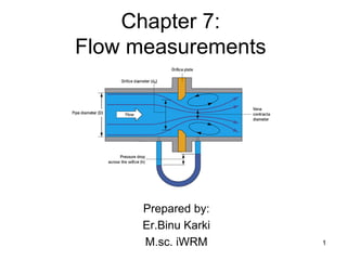
  • 35. Flow measurement Device: Orifice meter/Orifice Plate • It is a device used for measuring rate of flow of fluid through a pipe. • It is cheaper in comparison to venturimeter but it works on same principle as venturimeter. • It consists of a flat circular plate which has a circular sharp edged hole called orifice which is concentric with the pipe. • The orifice diameter is generally kept 0.5 times the diameter of pipe.(normally 0.4-0.8 times pipe diameter can be used) • A differential manometer is connected at a distance(1.5-2 times pipe dia)in u/s and (0.5 times orifice dia)distance in d/s from orifice plate. 35
  • 36. Flow measurement Device: Orifice meter/Orifice Plate 36
  • 37. Expression for rate of flow through Orifice plate/meter 37
  • 38. Expression for rate of flow through Orifice plate/meter 38
  • 39. Expression for rate of flow through Orifice plate/meter 39 • For Orifice meter, Q= Where, Cd= Coefficient of discharge for orifice meter The Cd value of orifice meter is much smaller than that for venturimeter.
  • 40. Flow measurement Device: Pitot tube 40 • It is a device used for measuring the velocity of flow at any point in a pipe/channel. • It is based on the principle that “When velocity of flow at a point becomes zero, the pressure there is increased due to conversion of kinetic energy into pressure energy” • The common type of pitot tube consists of a glass tube bent at right angles.
  • 41. Flow measurement Device: Pitot tube 41 • In fig, the lower end is bent through 90 ₒ upwards • The liquid rises up in it due to conversion of kinetic energy into pressure energy. • The velocity is measured by measuring the rise of liquid in the tube.
  • 44. Flow measurement Device: Nozzle meter 44 • It is used to measure discharge through the pipes. • Nozzle meter is similar to venturimeter with its divergent part omitted so the basic equations are same. • Its coefficient of discharge is same as that of venturimeter.
  • 45. Notches and Weirs 45 Notch • A notch is a device used for measuring the rate of flow of liquid through a small channel or a tank. • It may be defined as a opening in the side of the tank or small channel in such a way that the liquid surface in the tank/channel is below top edge of the opening. • Notch is generally made of metallic plate.
  • 46. Notches and Weirs 46 Weir • A Weir is a concrete/ masonry structure placed in an open channel over which flow occurs. • It is generally in the form of vertical wall, with the sharp edge at the top, running all the way across the open channel. • Weir is of big size in comparison to notch.
  • 47. Notches and Weirs 47 Classification of notches and weirs
  • 48. Notches and Weirs 48 Classification of notches and weirs
  • 49. Notches and Weirs 49 Discharge over rectangular notches and weirs Some terms: Nappe/Vein: The sheet of water flowing through the notch or weir Crest/Sill: The bottom edge of notch or top of weir over which water flows
  • 50. Notches and Weirs 50 Discharge over rectangular notches and weirs
  • 51. Velocity of Approach It is the velocity with which the water approaches or reaches the weir/notch before it flows over it. • If Va =velocity of approach Then, ha=additional head equal to Va2/2g due to velocity of approach acting on water flowing over the notch. H+ha=initial height over the notch ha= final height over the notch 51
  • 52. Velocity of Approach Process of determining Va: •Find discharge ‘Q’ over notch/weir neglecting the Va. •Divide Q by cross-sectional area of channel on the u/s side of weir/notch to find Va. •Find additional head ha. •Calculate discharge again including Va. 52
  • 53. Notches and Weirs 53 Discharge over triangular notches and weirs
  • 54. Notches and Weirs 54 Discharge over triangular notches and weirs
  • 55. Notches and Weirs 55 Discharge over triangular notches and weirs
  • 56. Notches and Weirs 56 Discharge over triangular notches and weirs If Va is taken into account, Then ha=additional head of water flowing over the weir/notch Or ha = Va2/2g The discharge Q over triangular notch/weir may be modified as,
  • 57. Notches and Weirs 57 Advantages of triangular notches/weirs over rectangular notch/weir Triangular notch/weir is preferred because: 1.The expression for discharge for a right angled V-notch/weir is very simple. 2.Triangular notch gives accurate results while measuring low discharge in comparison to rectangular notch/weir. 3.Only one reading of H is required for computation of discharge in case of triangular notch. 4.Ventilation of triangular notch is not necessary.
  • 58. Notches and Weirs 58 Discharge over trapezoidal notches and weirs A trapezoidal notch/weir is a combination of rectangular and triangular notch/weir. Thus the total discharge =discharge through a rectangular weir/notch + discharge through a triangular notch/weir. Let, H=height of water over the notch. L=length of the crest of the notch. Cd1=Coefficient of discharge through rectangular portion ABCD Cd2=coefficient of discharge for triangular portion(FAD and BCE)
  • 59. Notches and Weirs 59 Discharge over trapezoidal notches and weirs
  • 60. Notches and Weirs 60 Discharge over Cippoletti notches and weirs • Cipolletti weir is trapezoidal weir having side slopes of 1 horizontal to 4 vertical • By providing slopes on sides , an increase in discharge through the triangular portion ABC and DEF is obtained.
  • 61. Notches and Weirs 61 Discharge over stepped notches and weirs
  • 62. Emptying and filling of reservoir without inflow : rectangular/Cylindrical tank 62Cylindrical/Rectangular tank Conical tank
  • 63. Emptying and filling of reservoir without inflow:rectangular tank 63 Consider, H1=height of liquid above the center of the orifice provided on side/bottom of the tank t= time required for liquid to fall from H1 to H2 above the center of opening Let at any instant , h= height of liquid above orifice at an instant Let the liquid surface fall by small amount dh in time dt. A=horizontal cross-sectional of the tank Q= discharge through the orifice Volume of liquid discharged during time dt is Qdt.
  • 64. Emptying and filling of reservoir without inflow:rectangular tank 64 As the volume of liquid leaving the tank is equal to the volume of liquid flowing through the orifice/mouthpiece during the same interval of time. we have, A(-dh)=Qdt (negative sign because as time increases head decreases) If a=cross-sectional area of orifice/mouthpiece and Cd=coefficient of discharge then,
  • 65. Emptying and filling of reservoir without inflow :rectangular tank 65
  • 66. Emptying and filling of reservoir without inflow:rectangular tank 66 If the tank is completely emptied then H2 =0 becomes
  • 67. Emptying and filling of reservoir without inflow: conical tank 67
  • 68. Emptying and filling of reservoir without inflow:conical tank 68
  • 69. Emptying and filling of reservoir without inflow:conical tank 69
  • 70. Emptying and filling of reservoir with inflow: rectangular tank 70 Consider, A=cross-sectional area of tank a= cross-sectional area of orifice/mouthpiece Q=constant inflow of liquid which is also discharging through orifice t= time in which liquid level changes from H1 to H2 above the center of the orifice dt = time required to increase the water level by dh. q= discharge through the orifice Volume of liquid added to the tank=Adh In time dt the volume of inflow in tank=Qdt Volume of outflow through the orifice=qdt
  • 71. Emptying and filling of reservoir with inflow: rectangular tank 71
  • 72. Emptying and filling of reservoir with inflow: rectangular tank 72
  • 73. Emptying and filling of reservoir with inflow: rectangular tank 73