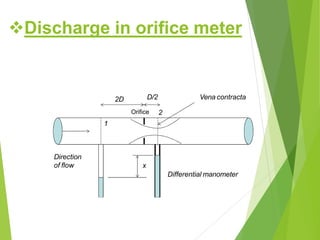
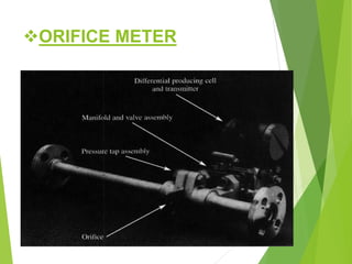
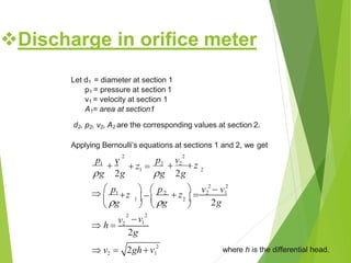
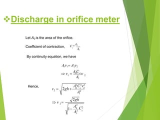
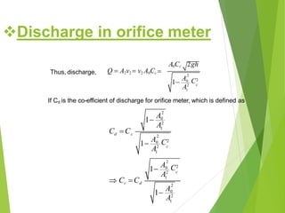
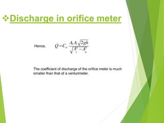
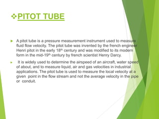
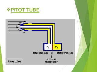
Government Engineering College
Valsad
( )
:SUBJECT:
Flow measurment using pitot tube, venturi
meter & pipe orifices
Department:-
Environmental Engineering
Guided by:-
Pro. Dhruti Patel
•Prepared by:-
1) Bhadani Ashishkumar J. 160190113003
2) Butani Henil R. 160190113006
3) Dankhara Nirmalbhai D. 160190113009
4) Patel Smit P. 160190113040
Venturimeter
 It’s Device, used to measure the rate of flow of
fluid through a pipe.
 The equation is based on the Bernoulli equation,
conservation of energy, and the continuity
equation.
 It consists of:
1.Inlet section
2.Convergent Section
3.A cylindrical throat
4.A gradually divergent cone
Venturimeter
Working of venturimeter
• The fluid whose flow rate isto be measured enters
the entry section of the venturimeter with a pressure
P1.
• As the fluid from the entry section of venturimeter
flows into the converging section, it’spressure
keeps on reducing and attains a minimum value
P2 when it enters the throat.
• That is,in the throat, the fluid pressure P2 will be
minimum.
• The differential pressure sensor attached
between the entry and throat section of
the venturimeter records the pressure
difference(P1-P2) which becomes an
indication of the flow rate of the fluid
through the pipe when calibrated.
• The diverging section has been provided
to enable the fluid to regain it’s pressure
and hence it’skinetic energy. Lesser the
angle of the diverging section, greater is
the recovery.
Working of venturimeter
Characteristic of venturimeter
• There isno restriction to the flow down the
pipe.
• They can be manufactured to fit any
required pipe size.
• The temperature and pressure within the
pipe does not affect the meter or its
accuracy.
• There are nomoving parts.
• The accurate shape required of the
inside of the meter makes them
relatively expensive to manufactured.
Formula of venturimeter
 Pressure difference (H) : 12.6*h
 Theoretically Discharge:
 Discharge:
 Where, Cd = Co-efficient of Discharge
A1 = Area of inlet of venturimeter
A2 = Area of throat of venturimeter
ORIFICE METER
• The venturimeter described earlier is a
reliable flow measuring device.
• Furthermore, it causes little pressure loss.
• For these reasons it is widely used,
particularly for large- volume liquid and gas
flows.
• However this meter is relatively complex to
construct and hence expensive.
• Especially for small pipelines, its cost seems
prohibitive, so simpler devices such as orifice meters
are used.
1
2
x
Direction
of flow
Orifice
Differential manometer
2D D/2 Vena contracta
Discharge in orifice meter
ORIFICE METER
Discharge in orifice meter
Let d1 = diameter at section 1
p1 = pressure at section 1
v1 = velocity at section 1
A1= area at section1
d2, p2, v2, A2 are the corresponding values at section 2.
Applying Bernoulli’s equations at sections 1 and 2, we get
2 2
2
1 2
g 2g g 2g

p v1 1
 z  
p v2
 z
2 2
2
2 1
2g
 v 2
 v2
  p   p1
z  2
 z  2 1
 g 1  g 2 
   
v1
 h 
v2
2g
 v  2ghv where h is the differential head.
Let A0 is the area of the orifice.
Coefficient of contraction, c
C A2
A0
1 2
A1
By continuity equation, we have
A1v1 A2v2
 v 
A0C c v
Hence,
c
A2C2v2
A2
1
2gh
C2
A2
1
v2  2gh  0 c 2
2 v 
1
A2
0
Discharge in orifice meter
Thus, discharge, 2
c
C2
A2
1
A0Cc 2gh
Q  A2v2  v2 A0Cc 
1
A0
If Cd is the co-efficient of discharge for orifice meter, which is defined as
2
1
A0
2
2
2
d c
c
c
A2
1
C2
A2
1
C2
A2
1
A2
1
C C
1
A0
1
A0
c C Cd
1
A0
Discharge in orifice meter
Hence,
The coefficient of discharge of the orifice meter is much
smaller than that of a venturimeter.
A0 A1 2gh
Q Cd
 A2A2
1 0
Discharge in orifice meter
PITOT TUBE
 A pitot tube is a pressure measurement instrument used to measure
fluid flow velocity. The pitot tube was invented by the french engineer
Henri pitot in the early 18th century and was modified to its modern
form in the mid-19th century by french scientist Henry Darcy.
 It is widely used to determine the airspeed of an aircraft, water speed
of about, and to measure liquid, air and gas velocities in industrial
applications. The pitot tube is used to measure the local velocity at a
given point in the flow stream and not the average velocity in the pipe
or conduit.
PITOT TUBE
Types of Pitot tube
 The basic pitot tube consists of a tube pointing
directly into the fluid flow. As this tube contains
fluid, a pressure can be measured; the moving
fluid is brought to rest (stagnates) as there is
no outlet to allow flow to continue.
 This pressure is the stagnation pressure of the
fluid, also known as the total pressure or
(particularly in aviation) the pitot pressure.
 The liquid flows up the tube and when
equilibrium is attained, the liquid reaches a
height above the free surface of the water
stream
Working of Pitottube
 Measurement of static pressure in this case is
made at the boundary of the wall (Fig.-1). The
axis of the tube measuring the static pressure
must be perpendicular to the boundary and free
from burrs, so that the boundary is smooth and
hence the streamlines adjacent to it are not
curved. This is done to sense the static pressure
only without any part of the dynamic pressure.
 A Pitot tube is also inserted as shown (Fig.-2) to
sense the stagnation pressure. The ends of the
Pitot tube, measuring the stagnation pressure,
and the piezometric tube, measuring the static
pressure, may be connected to a suitable
differential manometer for the determination of
flow velocity and hence the flow rate.
Cont……..
Fig.-1 Fig.-2
 In industry, the velocities being measured are
often those flowing in ducts and tubing where
measurements by an anemometer would be
difficult to obtain. In these kinds of
measurements, the most practical instrument to
use is the pitot tube.
 The pitot tube can be inserted through a small
hole in the duct with the pitot connected to a U-
tube water gauge or some other differential
pressure gauge for determining the velocity
inside the ducted wind tunnel. One use of this
technique is to determine the volume of air that is
being delivered to a conditioned space.
Operations:
 measurement of the flow of fluid by the venturimeter and the pitot tube and pipe orifice

measurement of the flow of fluid by the venturimeter and the pitot tube and pipe orifice

  • 1.
    Government Engineering College Valsad () :SUBJECT: Flow measurment using pitot tube, venturi meter & pipe orifices Department:- Environmental Engineering Guided by:- Pro. Dhruti Patel
  • 2.
    •Prepared by:- 1) BhadaniAshishkumar J. 160190113003 2) Butani Henil R. 160190113006 3) Dankhara Nirmalbhai D. 160190113009 4) Patel Smit P. 160190113040
  • 3.
    Venturimeter  It’s Device,used to measure the rate of flow of fluid through a pipe.  The equation is based on the Bernoulli equation, conservation of energy, and the continuity equation.  It consists of: 1.Inlet section 2.Convergent Section 3.A cylindrical throat 4.A gradually divergent cone
  • 4.
  • 5.
    Working of venturimeter •The fluid whose flow rate isto be measured enters the entry section of the venturimeter with a pressure P1. • As the fluid from the entry section of venturimeter flows into the converging section, it’spressure keeps on reducing and attains a minimum value P2 when it enters the throat. • That is,in the throat, the fluid pressure P2 will be minimum.
  • 6.
    • The differentialpressure sensor attached between the entry and throat section of the venturimeter records the pressure difference(P1-P2) which becomes an indication of the flow rate of the fluid through the pipe when calibrated. • The diverging section has been provided to enable the fluid to regain it’s pressure and hence it’skinetic energy. Lesser the angle of the diverging section, greater is the recovery. Working of venturimeter
  • 7.
    Characteristic of venturimeter •There isno restriction to the flow down the pipe. • They can be manufactured to fit any required pipe size. • The temperature and pressure within the pipe does not affect the meter or its accuracy. • There are nomoving parts. • The accurate shape required of the inside of the meter makes them relatively expensive to manufactured.
  • 8.
    Formula of venturimeter Pressure difference (H) : 12.6*h  Theoretically Discharge:  Discharge:  Where, Cd = Co-efficient of Discharge A1 = Area of inlet of venturimeter A2 = Area of throat of venturimeter
  • 9.
    ORIFICE METER • Theventurimeter described earlier is a reliable flow measuring device. • Furthermore, it causes little pressure loss. • For these reasons it is widely used, particularly for large- volume liquid and gas flows. • However this meter is relatively complex to construct and hence expensive. • Especially for small pipelines, its cost seems prohibitive, so simpler devices such as orifice meters are used.
  • 10.
    1 2 x Direction of flow Orifice Differential manometer 2DD/2 Vena contracta Discharge in orifice meter
  • 11.
  • 12.
    Discharge in orificemeter Let d1 = diameter at section 1 p1 = pressure at section 1 v1 = velocity at section 1 A1= area at section1 d2, p2, v2, A2 are the corresponding values at section 2. Applying Bernoulli’s equations at sections 1 and 2, we get 2 2 2 1 2 g 2g g 2g  p v1 1  z   p v2  z 2 2 2 2 1 2g  v 2  v2   p   p1 z  2  z  2 1  g 1  g 2      v1  h  v2 2g  v  2ghv where h is the differential head.
  • 13.
    Let A0 isthe area of the orifice. Coefficient of contraction, c C A2 A0 1 2 A1 By continuity equation, we have A1v1 A2v2  v  A0C c v Hence, c A2C2v2 A2 1 2gh C2 A2 1 v2  2gh  0 c 2 2 v  1 A2 0 Discharge in orifice meter
  • 14.
    Thus, discharge, 2 c C2 A2 1 A0Cc2gh Q  A2v2  v2 A0Cc  1 A0 If Cd is the co-efficient of discharge for orifice meter, which is defined as 2 1 A0 2 2 2 d c c c A2 1 C2 A2 1 C2 A2 1 A2 1 C C 1 A0 1 A0 c C Cd 1 A0 Discharge in orifice meter
  • 15.
    Hence, The coefficient ofdischarge of the orifice meter is much smaller than that of a venturimeter. A0 A1 2gh Q Cd  A2A2 1 0 Discharge in orifice meter
  • 16.
    PITOT TUBE  Apitot tube is a pressure measurement instrument used to measure fluid flow velocity. The pitot tube was invented by the french engineer Henri pitot in the early 18th century and was modified to its modern form in the mid-19th century by french scientist Henry Darcy.  It is widely used to determine the airspeed of an aircraft, water speed of about, and to measure liquid, air and gas velocities in industrial applications. The pitot tube is used to measure the local velocity at a given point in the flow stream and not the average velocity in the pipe or conduit.
  • 17.
  • 18.
  • 19.
     The basicpitot tube consists of a tube pointing directly into the fluid flow. As this tube contains fluid, a pressure can be measured; the moving fluid is brought to rest (stagnates) as there is no outlet to allow flow to continue.  This pressure is the stagnation pressure of the fluid, also known as the total pressure or (particularly in aviation) the pitot pressure.  The liquid flows up the tube and when equilibrium is attained, the liquid reaches a height above the free surface of the water stream Working of Pitottube
  • 20.
     Measurement ofstatic pressure in this case is made at the boundary of the wall (Fig.-1). The axis of the tube measuring the static pressure must be perpendicular to the boundary and free from burrs, so that the boundary is smooth and hence the streamlines adjacent to it are not curved. This is done to sense the static pressure only without any part of the dynamic pressure.  A Pitot tube is also inserted as shown (Fig.-2) to sense the stagnation pressure. The ends of the Pitot tube, measuring the stagnation pressure, and the piezometric tube, measuring the static pressure, may be connected to a suitable differential manometer for the determination of flow velocity and hence the flow rate. Cont……..
  • 21.
  • 22.
     In industry,the velocities being measured are often those flowing in ducts and tubing where measurements by an anemometer would be difficult to obtain. In these kinds of measurements, the most practical instrument to use is the pitot tube.  The pitot tube can be inserted through a small hole in the duct with the pitot connected to a U- tube water gauge or some other differential pressure gauge for determining the velocity inside the ducted wind tunnel. One use of this technique is to determine the volume of air that is being delivered to a conditioned space. Operations: