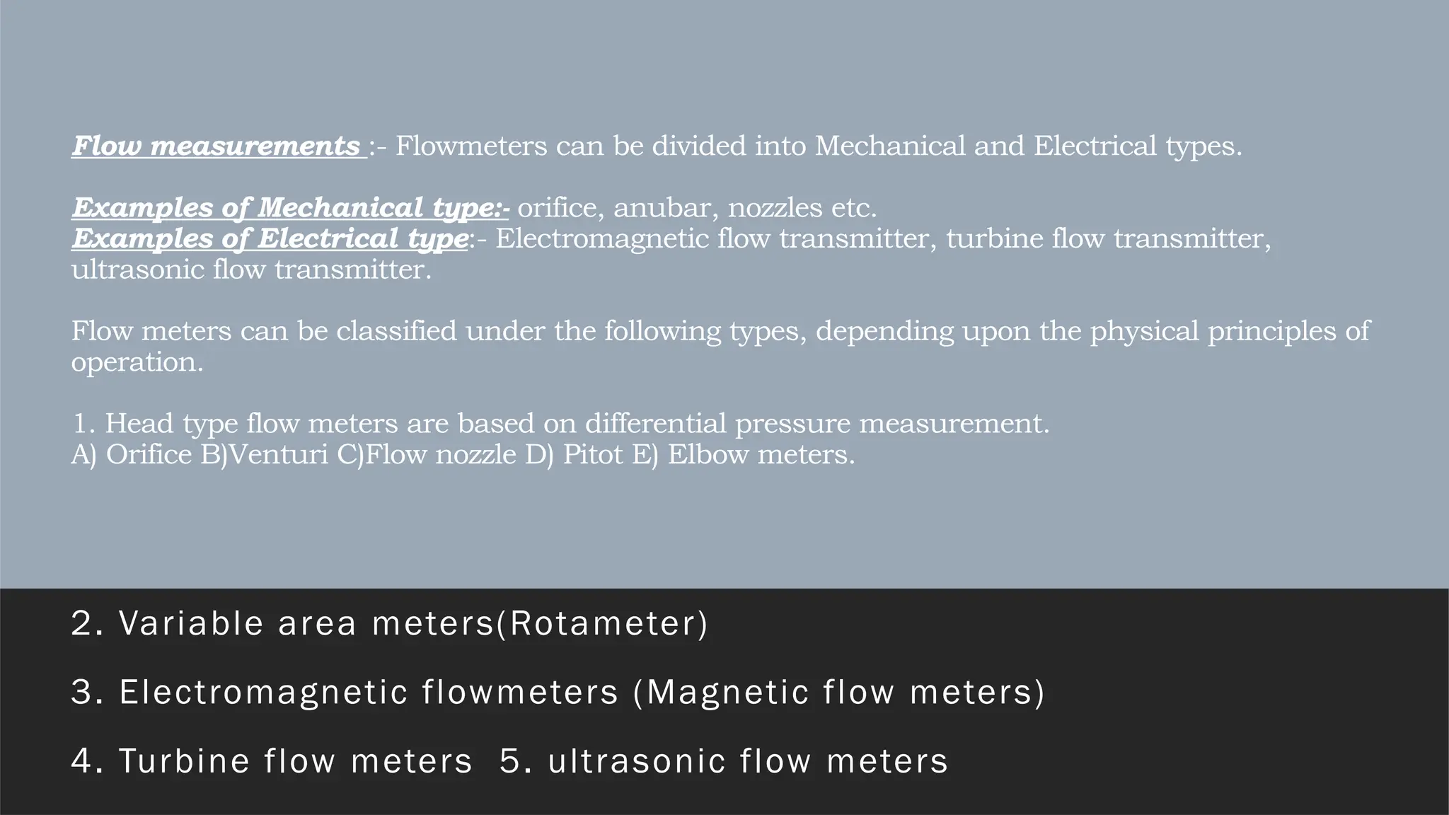
Flow measurements :-Flowmeters can be divided into Mechanical and Electrical types.
Examples of Mechanical type:- orifice, anubar, nozzles etc.
Examples of Electrical type:- Electromagnetic flow transmitter, turbine flow transmitter,
ultrasonic flow transmitter.
Flow meters can be classified under the following types, depending upon the physical principles of
operation.
1. Head type flow meters are based on differential pressure measurement.
A) Orifice B)Venturi C)Flow nozzle D) Pitot E) Elbow meters.
2. Variable area meters(Rotameter)
3. Electromagnetic flowmeters (Magnetic flow meters)
4. Turbine flow meters 5. ultrasonic flow meters
3.
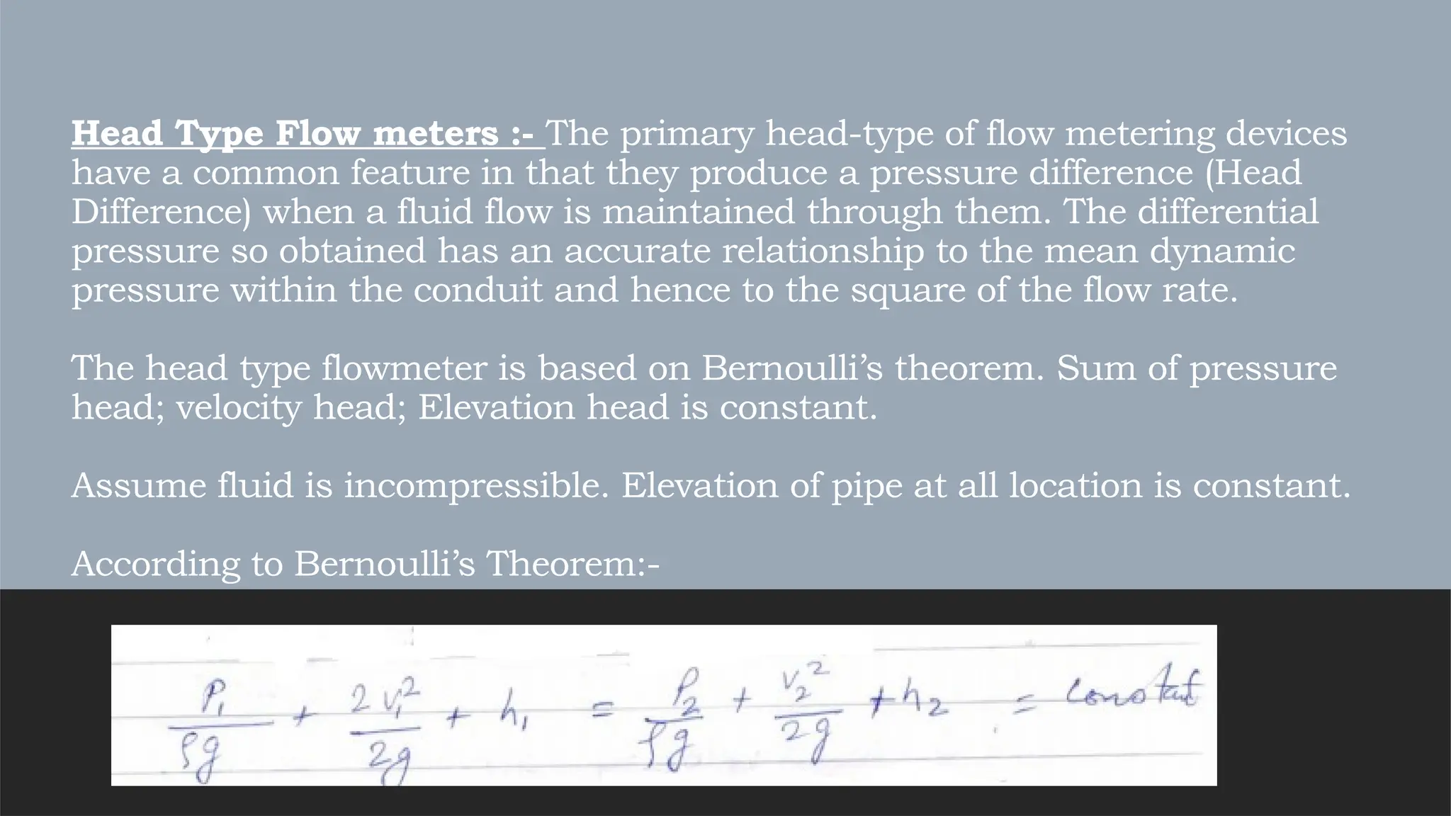
Head Type Flowmeters :- The primary head-type of flow metering devices
have a common feature in that they produce a pressure difference (Head
Difference) when a fluid flow is maintained through them. The differential
pressure so obtained has an accurate relationship to the mean dynamic
pressure within the conduit and hence to the square of the flow rate.
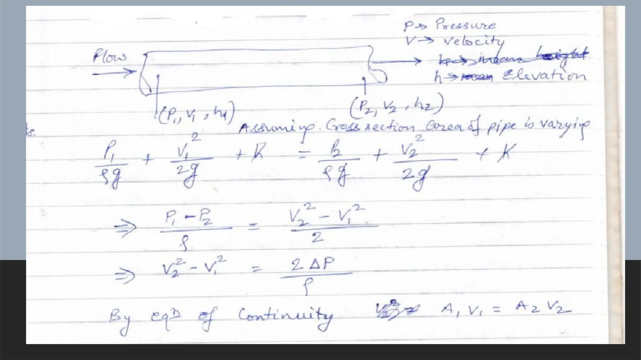
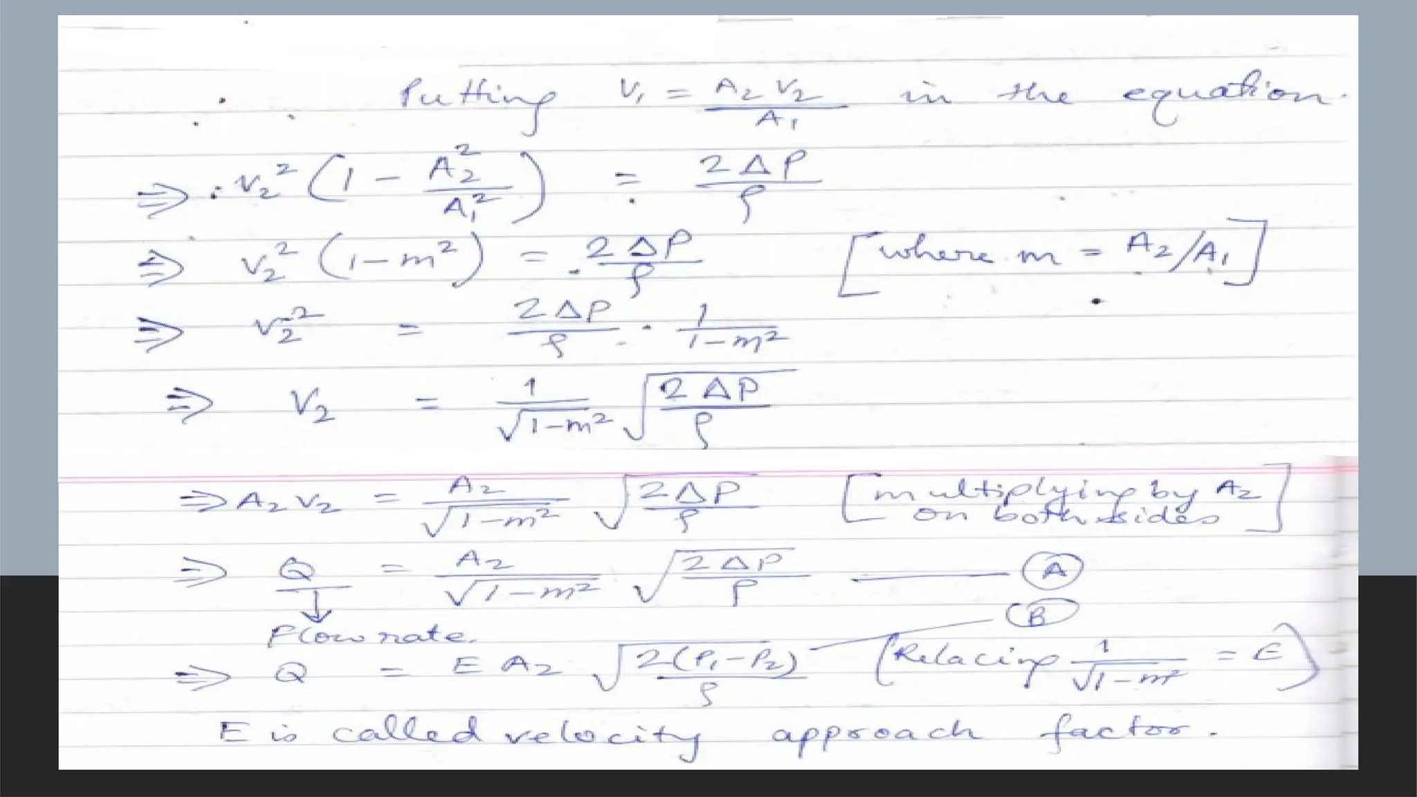
The head type flowmeter is based on Bernoulli’s theorem. Sum of pressure
head; velocity head; Elevation head is constant.
Assume fluid is incompressible. Elevation of pipe at all location is constant.
According to Bernoulli’s Theorem:-
6.
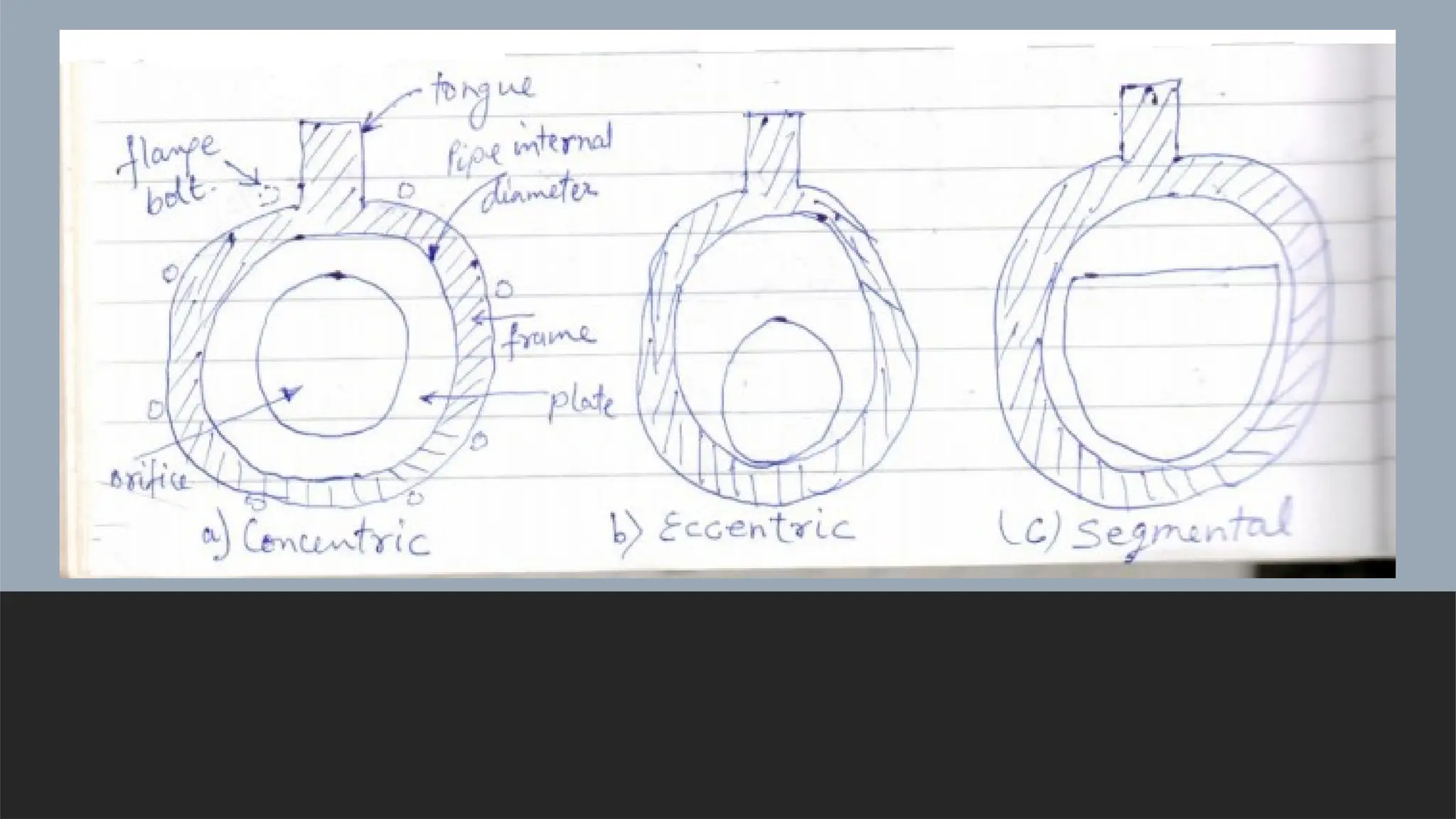
Orifice Meter:- Theorifice meter is the most common type of head flow
measuring device for medium and large –pipe sizes. The orifice plate inserted
in a pipe line causes an increase in the flow velocity and a corresponding
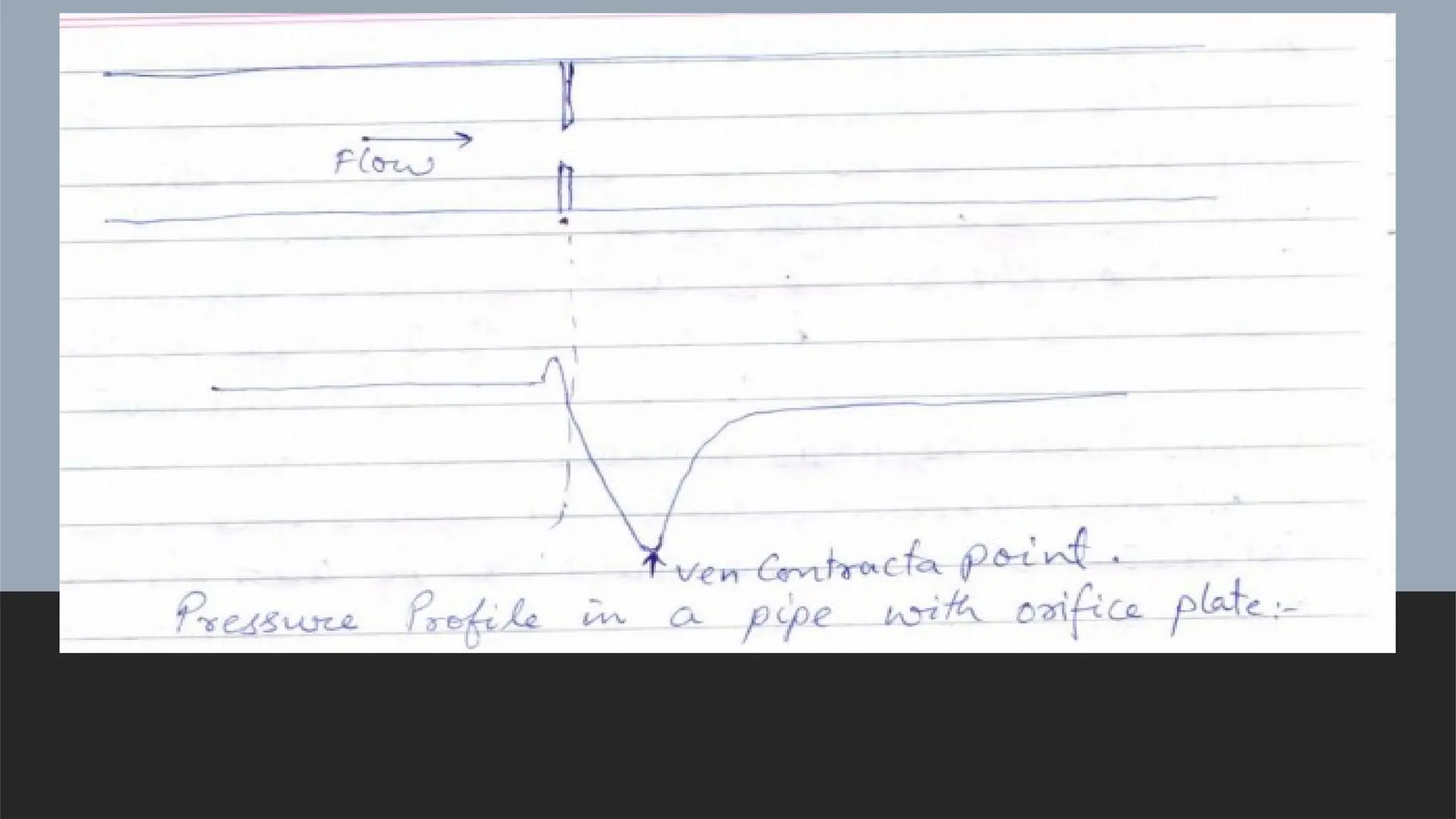
decrease in the pressure. The flow pattern shows an effective decrease in the
cross-section of flow beyond the orifice plate with the maximum velocity and
minimum pressure. The particular position where the velocity is maximum
and static pressure is minimum is known as Vena Contracta.
The orifice plate inserted in the line is basically a thin plate of metal with a
circular opening. The orifice configurations may be concentric, eccentric or
segmented.
9.
The stream orjet cross-section decreases in area after leaving the orifice
until it reaches the point, where the pressure is minimum and the velocity is
maximum. This is mainly due to the liquid being directed inward as it
approaches the orifice and also due to inertia effects persisting in this
direction for a distance after it leaves the orifice. The distance from the
orifice to this position varies with ratio of the orifice diameter to pipe
diameter, but an average value would be half the pipe diameter.
Accuracy of Orifice type flow is 2% of FS.
For a typical value of 0.6 for the orifice to the pipe dia ratio percentage loss
works out at 65% of the diff. pressure
Equation B cannot be applied directly to all the orifice plate
configurations due to friction and velocity distributions. Further, the
stream area contracts after leaving the orifice to the vena contracta
position.
10.
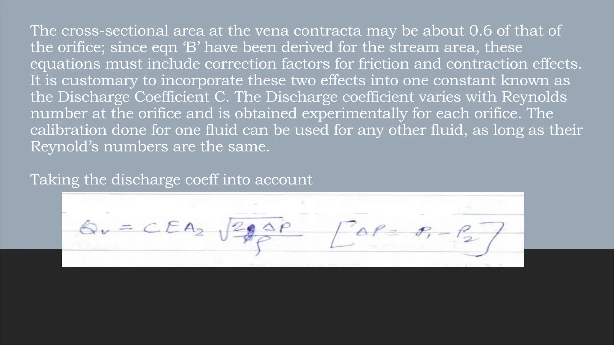
The cross-sectional areaat the vena contracta may be about 0.6 of that of
the orifice; since eqn ‘B’ have been derived for the stream area, these
equations must include correction factors for friction and contraction effects.
It is customary to incorporate these two effects into one constant known as
the Discharge Coefficient C. The Discharge coefficient varies with Reynolds
number at the orifice and is obtained experimentally for each orifice. The
calibration done for one fluid can be used for any other fluid, as long as their
Reynold’s numbers are the same.
Taking the discharge coeff into account
11.
Typical MOC:- Mildsteel, SS, Phosphor Bronze, Gunmetal.
Advantages:-
1) Orifice flowmeters consists of no moving parts.
2) The cost of orifice doesnot rise drastically according to their pipe size.
3) Simple construction and rugged.
4) Ease of installation.
5) Large data available.
Applicable code- BS1042, ISO 5167, IS 2952
12.
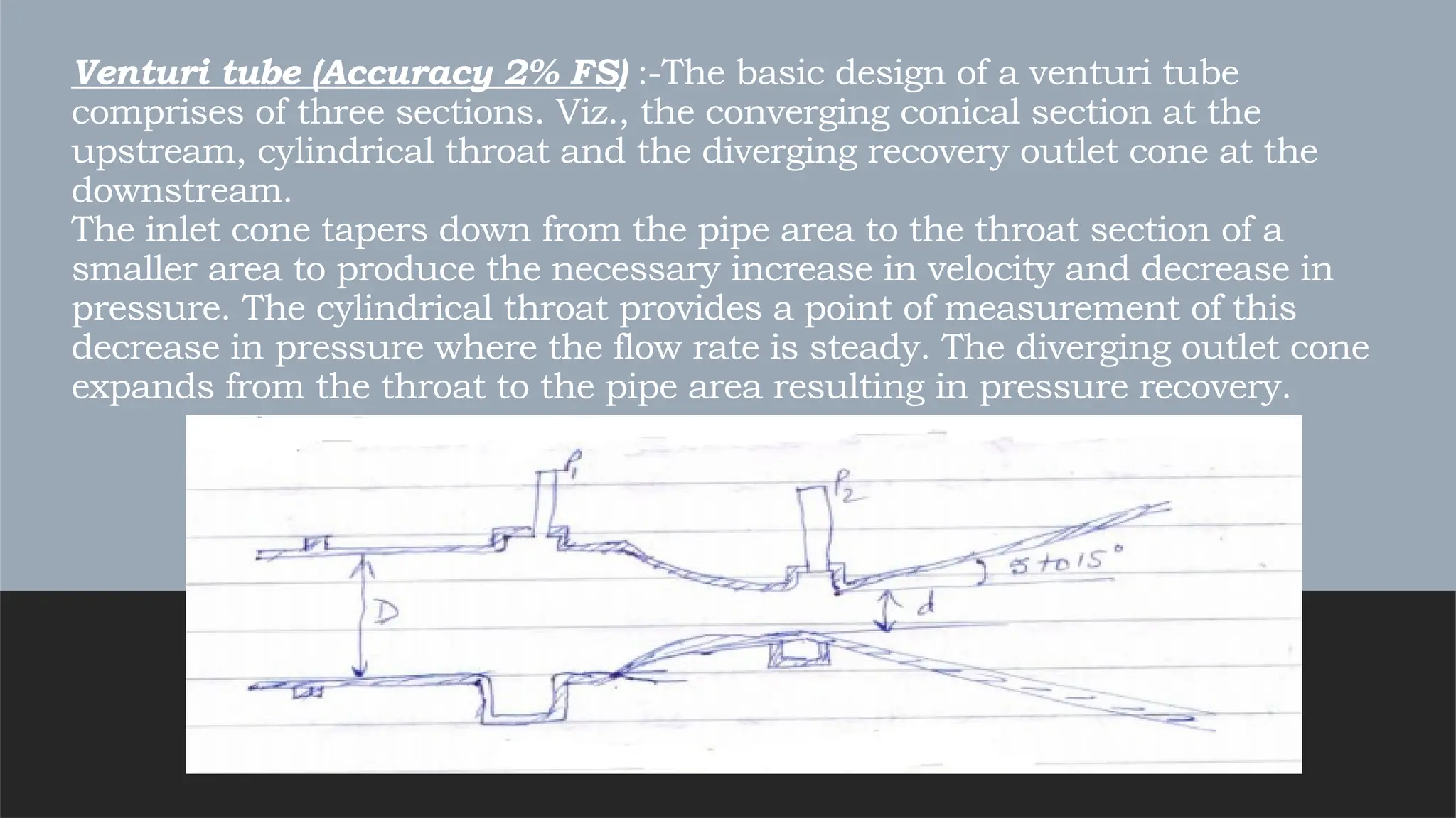
Venturi tube (Accuracy2% FS) :-The basic design of a venturi tube
comprises of three sections. Viz., the converging conical section at the
upstream, cylindrical throat and the diverging recovery outlet cone at the
downstream.
The inlet cone tapers down from the pipe area to the throat section of a
smaller area to produce the necessary increase in velocity and decrease in
pressure. The cylindrical throat provides a point of measurement of this
decrease in pressure where the flow rate is steady. The diverging outlet cone
expands from the throat to the pipe area resulting in pressure recovery.
13.
The inside surfacesare smoothly machined with holes drilled around the circumference at regular
intervals. This enables the pressure to be averaged before transmission to the measuring
instruments. The construction of the outlet cone is important. The pressure loss due to the
turbulent eddies caused by increasing diameter and due to the friction between the fluids and the
wall of the cone, affects the measurement. The pressure loss due to turbulent eddies can be
reduced by gradual expansion, while the frictional loss can be reduced by using a sharper cone.
The result is a compromise between the two requirements. In practice, two conical angles of 5 – 7
deg and 14 -15 deg with pressure losses of 11 to 18% respectively are used, which much lower
than that of the orifice plate. The discharge coeff is about 0.99 which means less delta P is
required for measurement, therefore resulting in a decrease in pressure loss.
Advantages:- less pressure loss than orifice, device is sufficiently resistant to abrasion, it is well
suited for suspended fluid.
Disadvantage:- The dimensions of venturi tube are relatively large and
its cost is also high.
14.
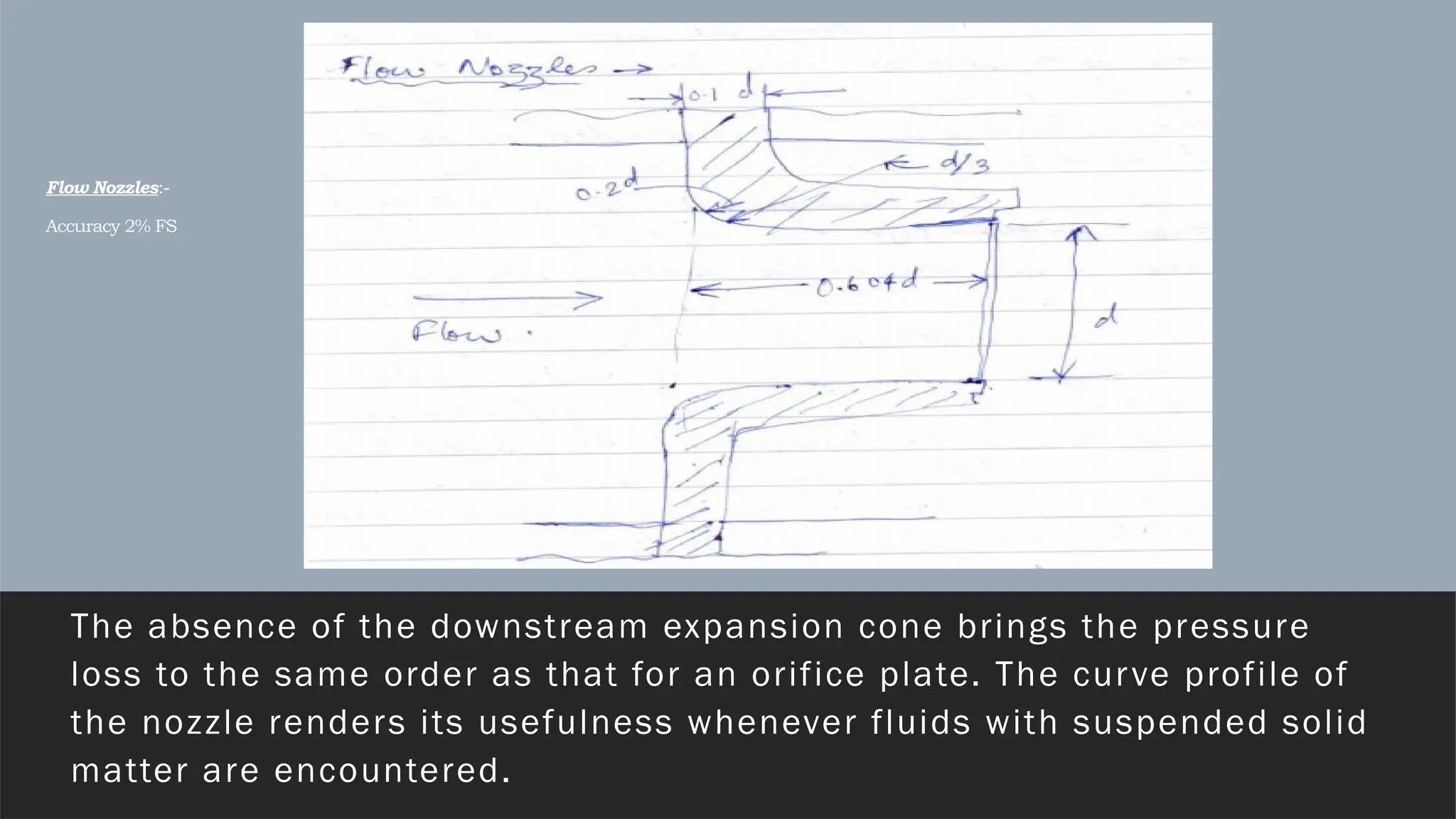
Flow Nozzles:-
Accuracy 2%FS
The absence of the downstream expansion cone brings the pressure
loss to the same order as that for an orifice plate. The curve profile of
the nozzle renders its usefulness whenever fluids with suspended solid
matter are encountered.
15.
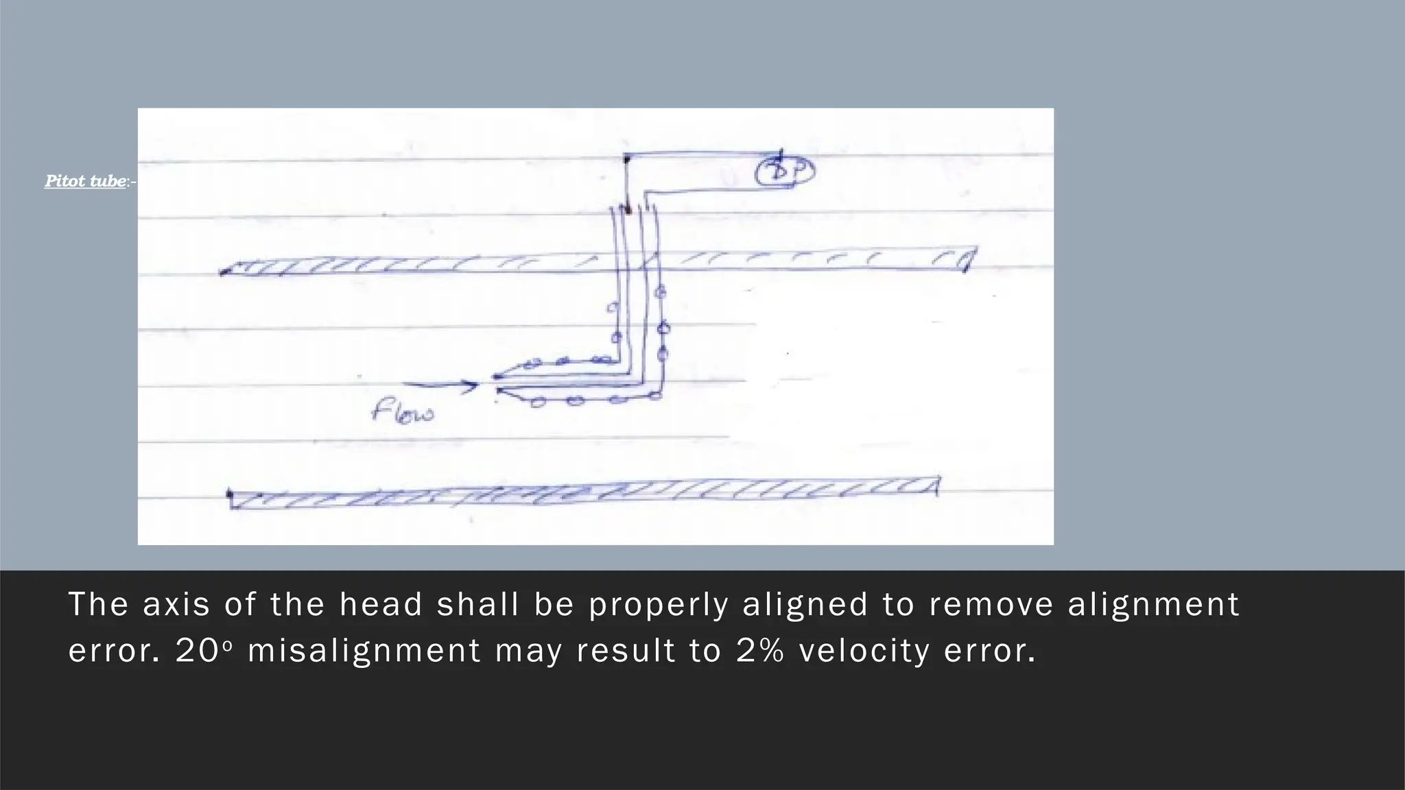
Pitot tube:- (Accuracy1% FS)
The axis of the head shall be properly aligned to remove alignment
error. 20o
misalignment may result to 2% velocity error.
16.
In this device,the velocity head is converted into an impact pressure, and the difference between the static pressure and the impact pressure is a measure of the flow rate. In other words kinetic energy is converted into Potential energy.
Advantage:- Pressure drop in pitot tube is very less for process pressure.
Disadvantages:- 1) The essential drawback with the pitot tube is that it can measure velocity at only one position in the cross section of the pipe.
2) not good for high viscous fluid.
3) Frequent choking problem due to small bores.
17.
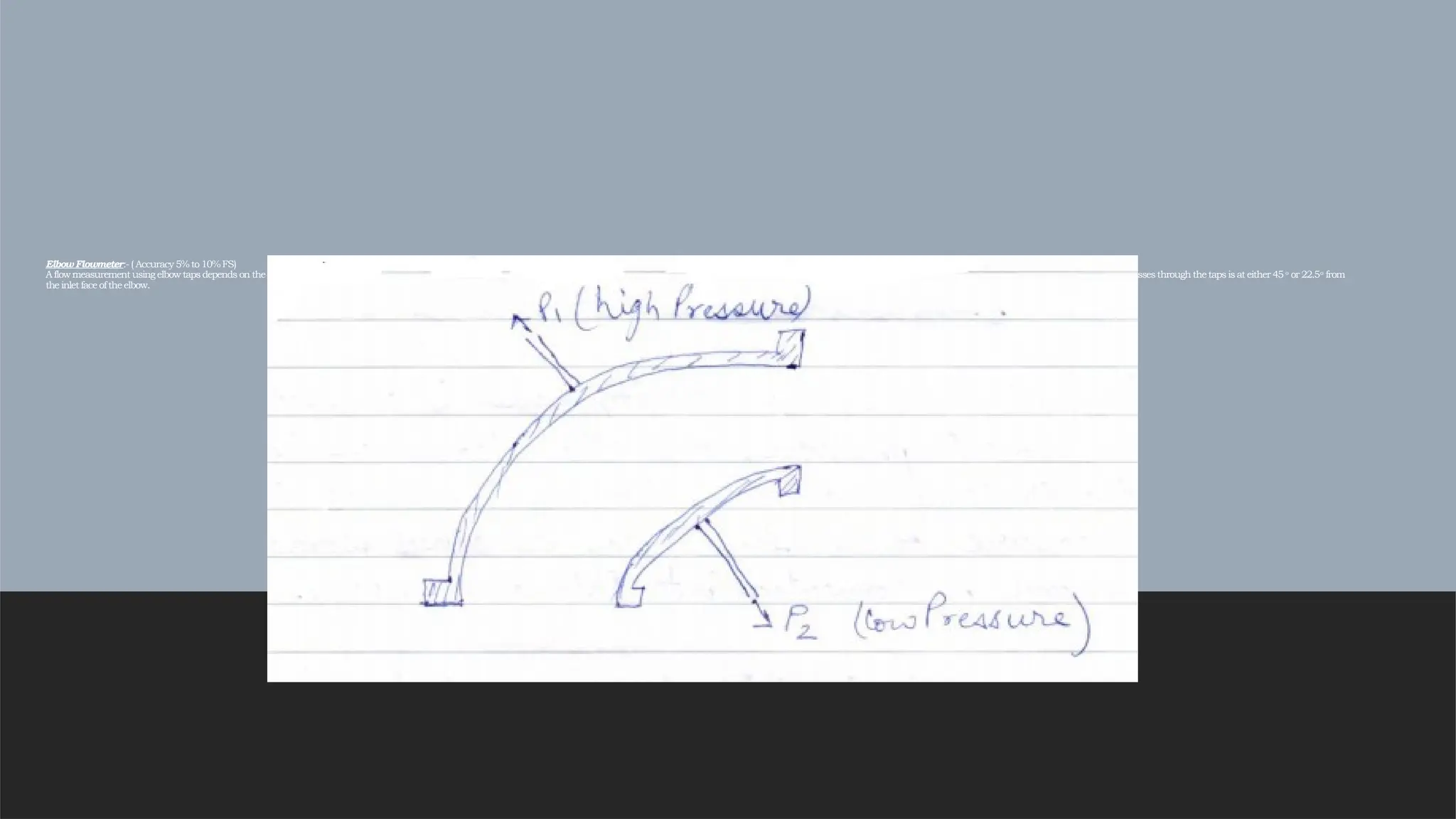
Elbow Flowmeter:- (Accuracy 5% to10%FS)
A flowmeasurement using elbow taps depends on the detection of the differential pressure developedby centrifugalforce as the directionsof fluidflowischangedin apipe elbow. Tapsare locatedon the inner andouter radii in the plane oftheelbow;the diameter which passesthrough the taps is at either 45 o
or 22.5o
from
the inlet face oftheelbow.
18.
It is recommendedto provide at least 25 pipe diameters of straight pipe upstream and 10 diameters downstream. When selecting an elbow for flow measurement purposes, it is
preferable to pick one that is located between two horizontal pipe sections. This will guarantee that the pressure taps will be horizontal and material will not accumulate in them.
Elbow taps develop relatively low differential pressures. For this reason, they can not be used for measurement of streams with low velocity.
19.
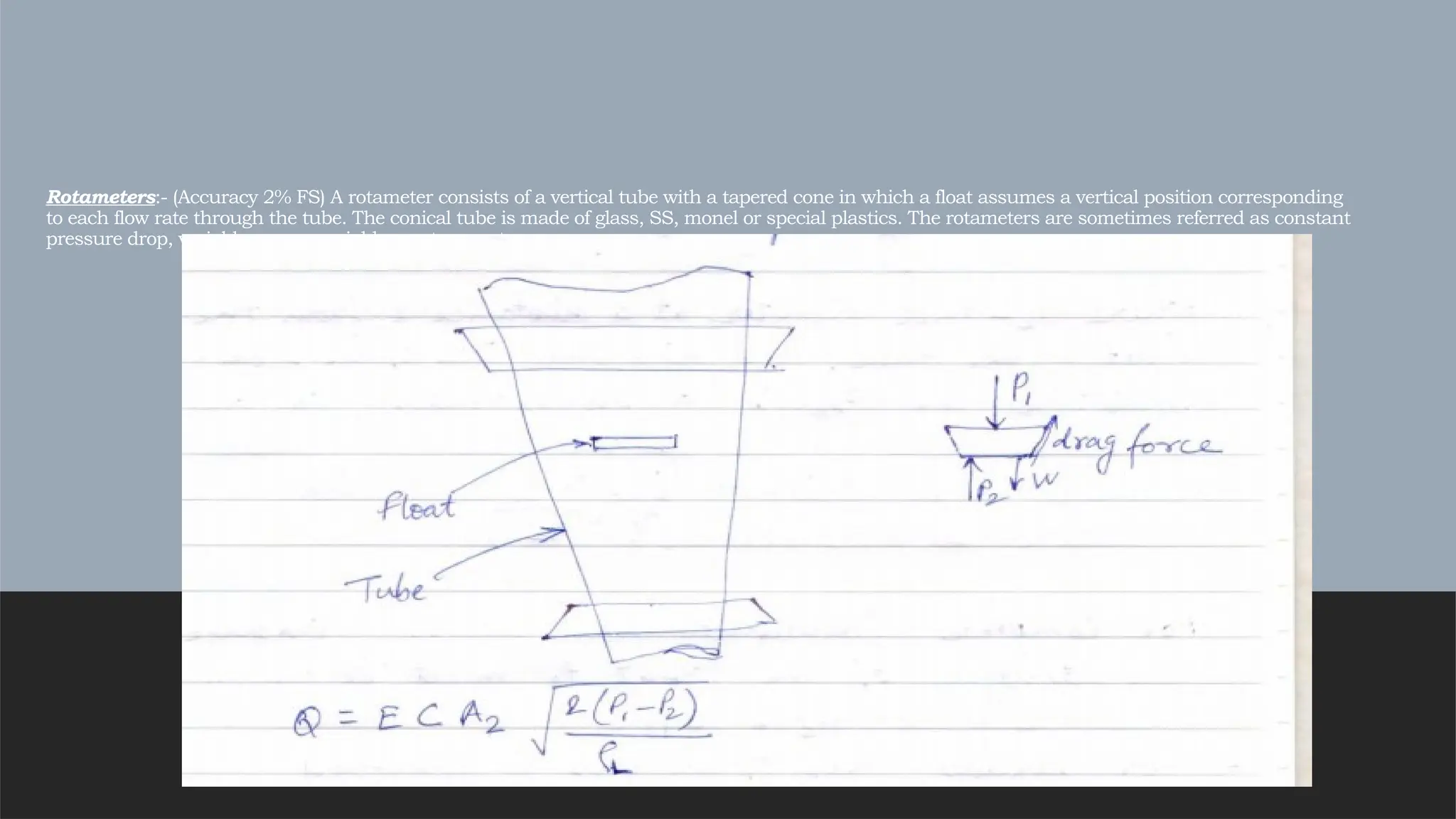
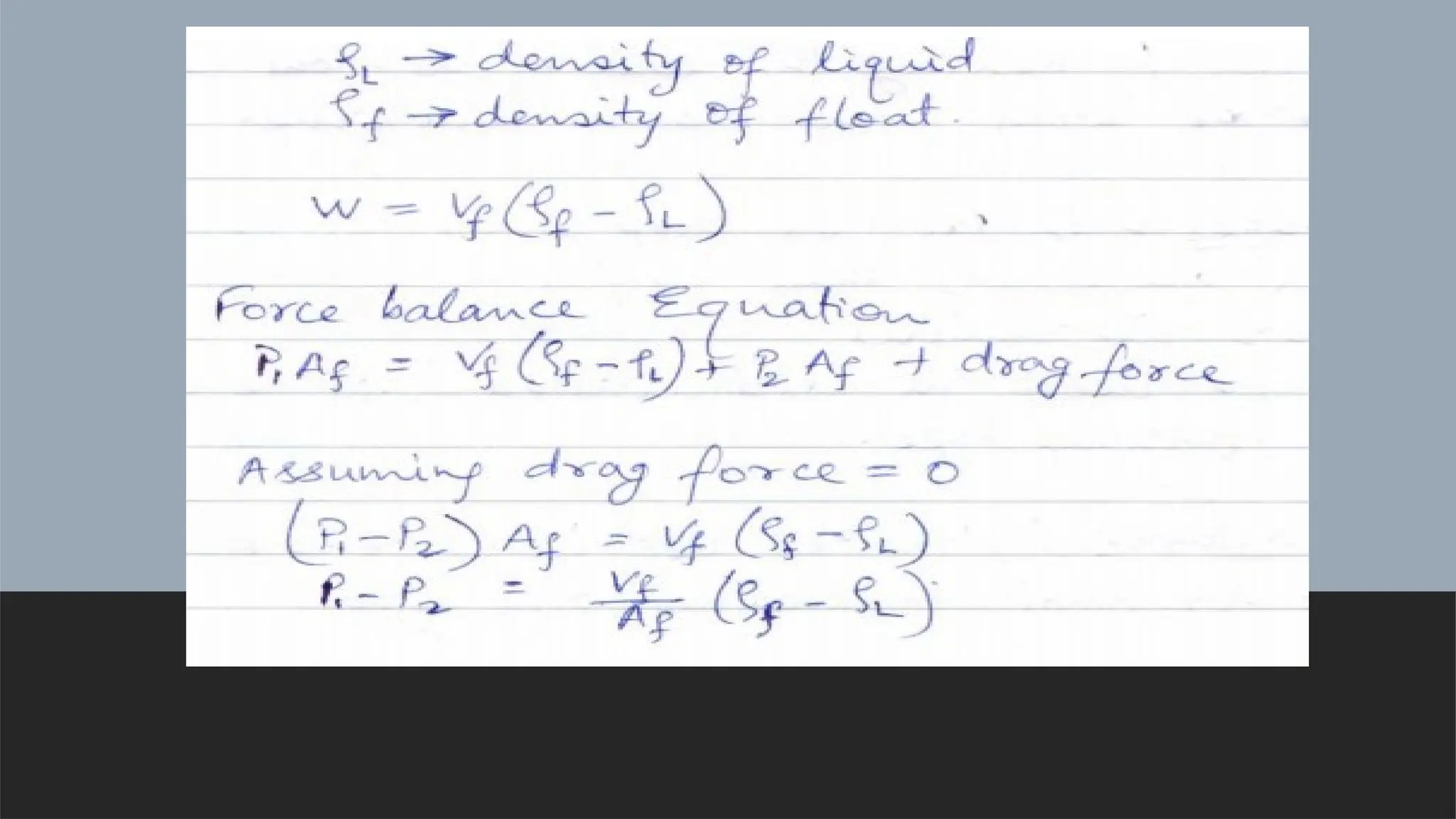
Rotameters:- (Accuracy 2%FS) A rotameter consists of a vertical tube with a tapered cone in which a float assumes a vertical position corresponding
to each flow rate through the tube. The conical tube is made of glass, SS, monel or special plastics. The rotameters are sometimes referred as constant
pressure drop, variable area or variable aperture meters.
22.
For liquids, thisconditions is achieved practically by making the body of
the float either hollow or with solid plastic material.
Advantages:- 1) Pressure drop is constant.
2) Better accuracy than orifice
3) Linear instrument
4) Can be used in contaminated fluid as it is self cleaning type.
Disadvantages:- 1) Limited use in viscous fluid.
2)Good for small to medium pipe size.
23.
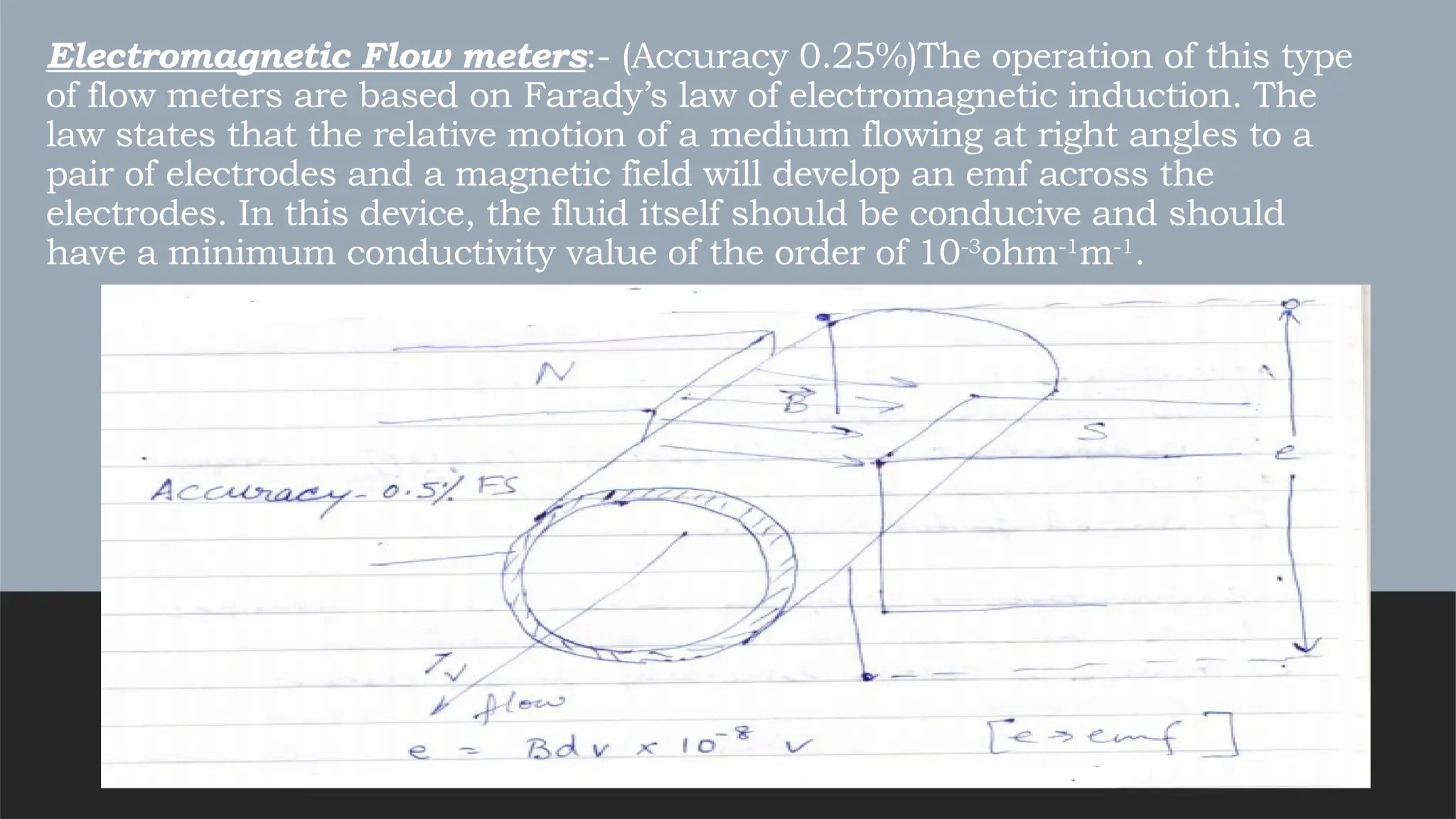
Electromagnetic Flow meters:-(Accuracy 0.25%)The operation of this type
of flow meters are based on Farady’s law of electromagnetic induction. The
law states that the relative motion of a medium flowing at right angles to a
pair of electrodes and a magnetic field will develop an emf across the
electrodes. In this device, the fluid itself should be conducive and should
have a minimum conductivity value of the order of 10-3
ohm-1
m-1
.
24.
B– Magnetic fluxdensity in Tesla
d– the distance between electrodes in metres.
V– Average velocity of the liquid in m/s.
The voltage is generated in a direction mutually perpendicular to both the velocity plane of the conducting liquid and
the plane of the magnetic field independent of Reynold’s number, viscosity and density of the liquid. Emf generated is
proportional to average velocity. Average velocity multiplied by cross section area gives volume flow.
Both AC and DC magnetic field can be used but DC method has the danger of electrolytic polarization at the
electrodes.
Fleming Right rule :- Thumb – Motion of the conductor.
Fore finger- Magnetic field
Middle finger- Induced emf.
25.
Advantages :- 1)No obstruction of flow.
2) No pressure drop.
3) Independent of fluid property ( Except minimum conductivity requirement)
4) Bidirectional Flow.
5) Suited for slurries.
Disadvantages :- 1) O/P in Micro volt range requires large amplification.
2) Device is costly especially small dia.
26.
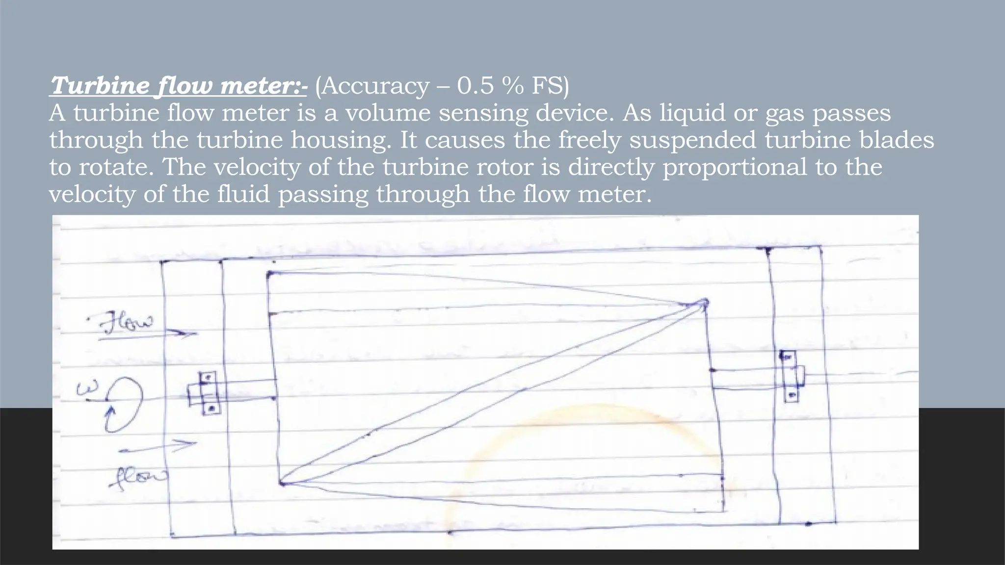
Turbine flow meter:-(Accuracy – 0.5 % FS)
A turbine flow meter is a volume sensing device. As liquid or gas passes
through the turbine housing. It causes the freely suspended turbine blades
to rotate. The velocity of the turbine rotor is directly proportional to the
velocity of the fluid passing through the flow meter.
27.
The instantaneous frequencyis the measure of the flow rate, and the total number of pulse over a period of
time is a measure of the total flow.
Blades of Flow meter is made up of magnetic SS, four nos. of pick-up coil with permanent magnet is
mounted at the periphery of and in same plane as the rotor. When rotor revolves, the reluctance of the
magnetic circuit is changed and a sinusoidal signal is induced.
Typical frequency of the order of 1 Khz are obtained for FS flow rates in these devices.
Advantages :- 1) Accuracy.
2) Repeatability is high.
3) Pressure drop is lesser than Orifice.
4) Dynamic response of Instrument is good.
Disadvantages :- 1) Instrumentation is susceptible to damages due to
particles suspended in the fluid.
2) Expensive Instrument. 3) Applicable in limited viscosity range.
28.
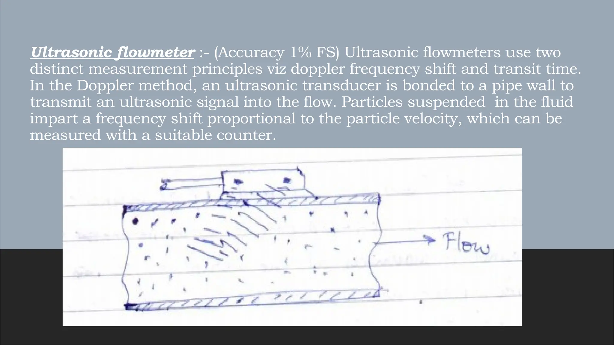
Ultrasonic flowmeter :-(Accuracy 1% FS) Ultrasonic flowmeters use two
distinct measurement principles viz doppler frequency shift and transit time.
In the Doppler method, an ultrasonic transducer is bonded to a pipe wall to
transmit an ultrasonic signal into the flow. Particles suspended in the fluid
impart a frequency shift proportional to the particle velocity, which can be
measured with a suitable counter.
29.
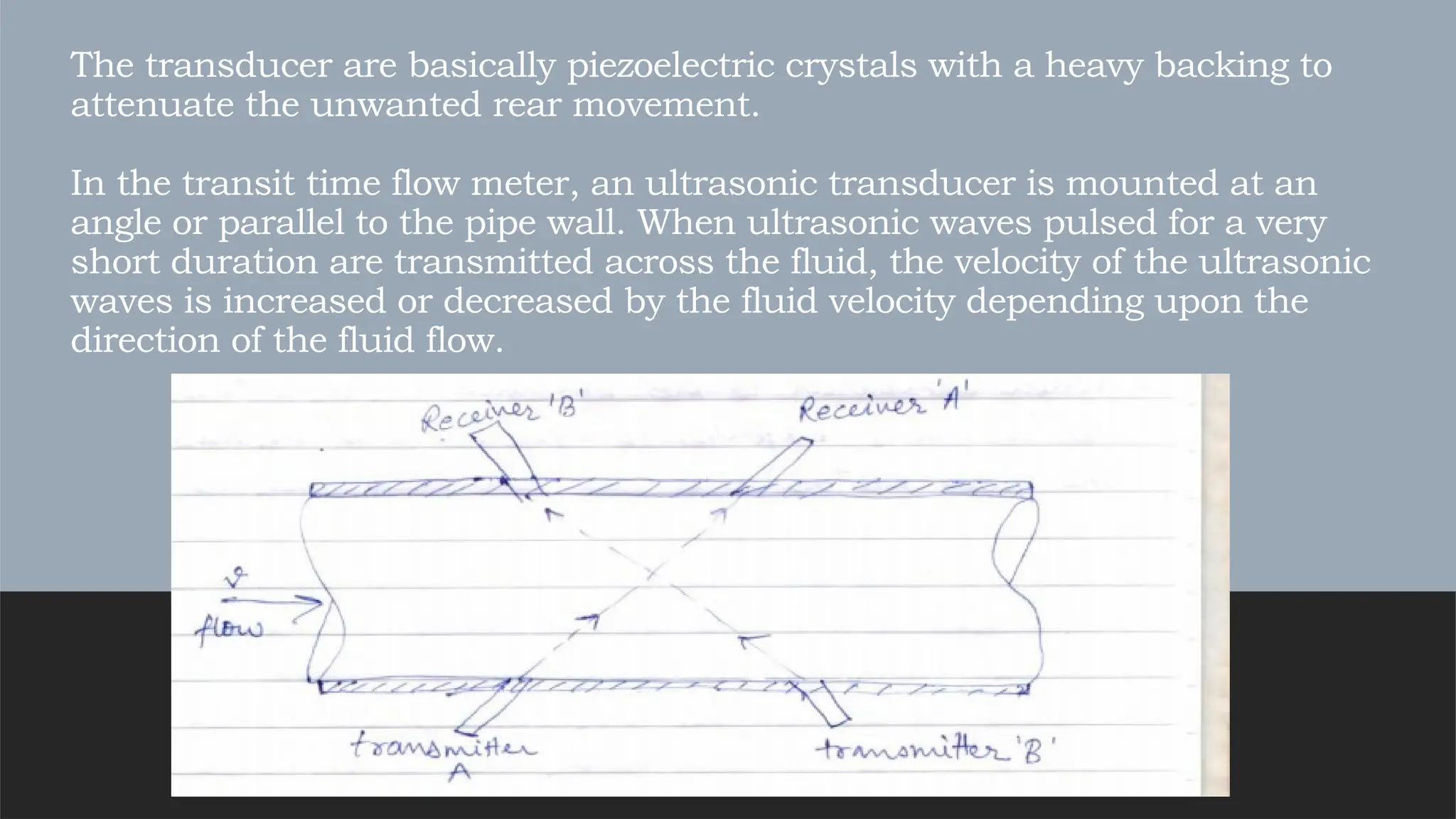
The transducer arebasically piezoelectric crystals with a heavy backing to
attenuate the unwanted rear movement.
In the transit time flow meter, an ultrasonic transducer is mounted at an
angle or parallel to the pipe wall. When ultrasonic waves pulsed for a very
short duration are transmitted across the fluid, the velocity of the ultrasonic
waves is increased or decreased by the fluid velocity depending upon the
direction of the fluid flow.
30.
Advantages :- 1)The measurement is insensitive to viscosity, pressure and
temperature variations.
2) Flow measurement can be bi-directional.
3) Good Accuracy, fast response, wide frequency range.
Disadvantages :- 1) Costly instrument.
2) the ultrasonic flowmeters are sophisticated when compared to the
mechanical flowmeters, so it needs experts to repair and maintain the flow
meters.