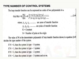
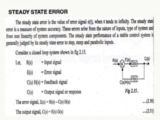
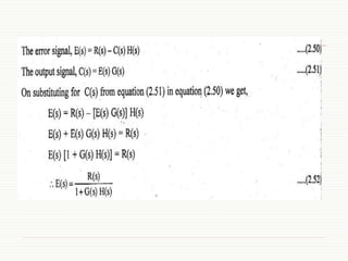
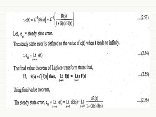
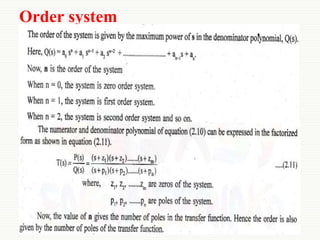
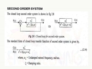
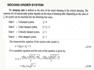
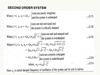
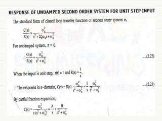
First & Second Order of the Control Systems
Presented by
Mr. C.S.Satheesh, M.E.,
Assistant Professor, Department of EEE,
Muthayammal Engineering College (Autonomous),
Namakkal (Dt), Rasipuram – 637408
MUTHAYAMMAL ENGINEERING COLLEGE
(An Autonomous Institution)
(Approved by AICTE, New Delhi, Accredited by NAAC, NBA & Affiliated to Anna University),
Rasipuram - 637 408, Namakkal Dist., Tamil Nadu, India.
Order system
Introduction - First order system
 The first order system has only one pole.
 Where
K is the D.C gain and
T is the time constant of the system.
 Time constant is a measure of how quickly a 1st order
system responds to a unit step input.
 D.C Gain of the system is ratio between the input signal
and the steady state value of output.
1


Ts
K
s
R
s
C
)
(
)
(
First order system
 Examples:
 The first order system given below.
1
3
10


s
s
G )
(
5
3


s
s
G )
(
1
5
1
5
3


s
/
/
• D.C gain is 10 and time constant is 3 seconds.
• For the following system
• D.C Gain of the system is 3/5 and time constant is 1/5 seconds.
Second Order System
 We have already discussed the transient response of 1st order
systems.
 Compared to the simplicity of a first-order system, a second-order
system exhibits a wide range of responses that must be analyzed
and described.
 Whereas, changes in the parameters of a second-order system can
change the form of the response.
 A second-order system can display characteristics much like a
first-order system or, depending on component values, display
damped or pure oscillations for its transient response.
10
t
t
c n

cos
1
)
( 

Problem 1
4
2
4
)
(
)
(
2



s
s
s
R
s
C
 Determine the un-damped natural frequency
and damping ratio of the following second
order system.
4
2

n

2
2
2
2 n
n
n
s
s
s
R
s
C






)
(
)
(
• Compare the numerator and denominator of the given transfer
function with the general 2nd order transfer function.
2

 n
 s
s
n 2
2 
 
4
2
2 2
2
2




 s
s
s
s n
n 

5
0.

 
1

 n

17
Problem 2
Problem 3
Static error constant for various type number
of system
Steady state error for various types of input
Problem 4
Problem 5
References :
 A.Nagoorkani, Control Systems,
RBA Publications.
4/5/2021 53
Thank You
54

First & second order of the control systems

  • 1.
    First & SecondOrder of the Control Systems Presented by Mr. C.S.Satheesh, M.E., Assistant Professor, Department of EEE, Muthayammal Engineering College (Autonomous), Namakkal (Dt), Rasipuram – 637408 MUTHAYAMMAL ENGINEERING COLLEGE (An Autonomous Institution) (Approved by AICTE, New Delhi, Accredited by NAAC, NBA & Affiliated to Anna University), Rasipuram - 637 408, Namakkal Dist., Tamil Nadu, India.
  • 2.
  • 3.
    Introduction - Firstorder system  The first order system has only one pole.  Where K is the D.C gain and T is the time constant of the system.  Time constant is a measure of how quickly a 1st order system responds to a unit step input.  D.C Gain of the system is ratio between the input signal and the steady state value of output. 1   Ts K s R s C ) ( ) (
  • 4.
    First order system Examples:  The first order system given below. 1 3 10   s s G ) ( 5 3   s s G ) ( 1 5 1 5 3   s / / • D.C gain is 10 and time constant is 3 seconds. • For the following system • D.C Gain of the system is 3/5 and time constant is 1/5 seconds.
  • 10.
    Second Order System We have already discussed the transient response of 1st order systems.  Compared to the simplicity of a first-order system, a second-order system exhibits a wide range of responses that must be analyzed and described.  Whereas, changes in the parameters of a second-order system can change the form of the response.  A second-order system can display characteristics much like a first-order system or, depending on component values, display damped or pure oscillations for its transient response. 10
  • 15.
  • 17.
    Problem 1 4 2 4 ) ( ) ( 2    s s s R s C  Determinethe un-damped natural frequency and damping ratio of the following second order system. 4 2  n  2 2 2 2 n n n s s s R s C       ) ( ) ( • Compare the numerator and denominator of the given transfer function with the general 2nd order transfer function. 2   n  s s n 2 2    4 2 2 2 2 2      s s s s n n   5 0.    1   n  17
  • 18.
  • 20.
  • 28.
    Static error constantfor various type number of system
  • 29.
    Steady state errorfor various types of input
  • 36.
  • 37.
  • 53.
    References :  A.Nagoorkani,Control Systems, RBA Publications. 4/5/2021 53
  • 54.