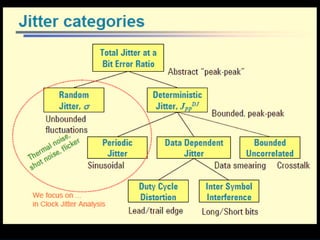
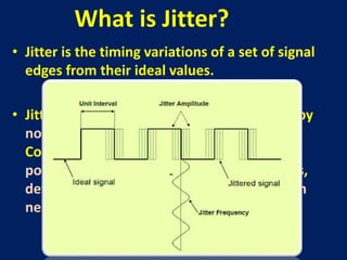
CLOCK JITTER
Presented By:
Maj AASP Athuldora arachchi
Sri Lanka Army
• Jitter is the timing variations of a set of signal
edges from their ideal values.
• Jitters in clock signals are typically caused by
noise or other disturbances in the system.
Contributing factors include thermal noise,
power supply variations, loading conditions,
device noise, and interference coupled from
nearby circuits.
What is Jitter?
Clock jitter
• most jitter in a electrical circuit is caused by thermal noise, which has a
Gaussian distribution, random jitter also follows a Gaussian distribution
(Normal distribution).
• Jitter can be quantified in the same terms as all time-varying signals, e.g.,
RMS.
• Also like other time-varying signals, jitter can be expressed in terms of
spectral density, e.g. ,phase noise. Sampling frequency is normally assumed to
be constant.
• Samples should be taken at regular intervals. If some jitter is present on the
clock signal, then it will produce an error proportional to the slew rate of the
input signal and to the absolute value of the clock error.
• Clock jitter originates from noise inside clock generator and from noise
inherent to the PLL(Phase-locked loop). Clock jitter directly translates into
sampling noise and adds to the overall sampling noise.
• As well as expressing the amount of jitter in time units, such as
Pico seconds and Nano seconds.
• jitter can also be expressed as the Unit Interval (UI).
• jitter amount is represented as Tj [ps], and the interval per bit is
represented as Tbit [ps]
• For example, using a 10 Gbit/s signal, the interval per bit is 100
ps. If there is jitter of 10 ps in this signal, the amount of jitter is
calculated as 0.1 UI.
Types of Jitter
Jitter can be measured in a number of ways;
the following are the major types of jitter:
• Period Jitter.
• Cycle to Cycle Period Jitter.
• Long Term Jitter.
• Phase Jitter.
• Time Interval Error (TIE).
Period Jitter
Period jitter is the deviation in cycle time of a clock signal
with respect to the ideal period over a number of
randomly selected cycles.
If we were given a number of individual clock periods, we
can measure each one and calculate the average clock
period as well as the standard deviation and the peak-to-
peak value.
Cycle-to-Cycle Jitter
• Cycle-to-cycle jitter is the difference in a clock’s
period from one cycle to the next. Cycle-to-cycle
jitter is the most difficult to measure usually
requiring a timing interval analyzer.
• As shown in Figure , J1 and J2 are the measured
jitter values. The maximum value measured over
multiple cycles is the maximum cycle-to-cycle
jitter.
Long-Term Jitter
• Long-term jitter measures the change in a clock’s output from the
ideal position, over several consecutive cycles.
• The actual number of cycles used in the measurement is
application dependent.
• Long-term jitter is different from period jitter and cycle-to-cycle
jitter because it represents the cumulative effect of jitter on a
continuous stream of clock cycles over a long time interval.
• That is why long-term jitter is sometimes referred to as the
accumulated jitter. Long term jitter is typically useful in
graphics/video displays and long-range telemetry applications
such as range finders.
Phase Jitter
• In a square wave, most of the energies are located at the
carrier frequency. However, some signal energies are
“leaked-out” over a range of frequencies on both sides of
the carrier.
• Phase jitter is the amount of phase noise energy
contained between two offset frequencies relative to the
carrier (fc). Figure is an unfiltered phase noise plot and
the shaded areas represent the phase jitter between
frequencies f1 and f2.
Time Interval Error (TIE)
• Time Interval Error (TIE) of an edge is the time
deviation of that edge from its ideal position
measured from a reference point. In effect, TIE is
the discrete time domain representation of
phase noise expressed in seconds or pico-
seconds.
Clock jitter

Clock jitter

  • 1.
    CLOCK JITTER Presented By: MajAASP Athuldora arachchi Sri Lanka Army
  • 2.
    • Jitter isthe timing variations of a set of signal edges from their ideal values. • Jitters in clock signals are typically caused by noise or other disturbances in the system. Contributing factors include thermal noise, power supply variations, loading conditions, device noise, and interference coupled from nearby circuits. What is Jitter?
  • 3.
    Clock jitter • mostjitter in a electrical circuit is caused by thermal noise, which has a Gaussian distribution, random jitter also follows a Gaussian distribution (Normal distribution). • Jitter can be quantified in the same terms as all time-varying signals, e.g., RMS. • Also like other time-varying signals, jitter can be expressed in terms of spectral density, e.g. ,phase noise. Sampling frequency is normally assumed to be constant. • Samples should be taken at regular intervals. If some jitter is present on the clock signal, then it will produce an error proportional to the slew rate of the input signal and to the absolute value of the clock error. • Clock jitter originates from noise inside clock generator and from noise inherent to the PLL(Phase-locked loop). Clock jitter directly translates into sampling noise and adds to the overall sampling noise.
  • 4.
    • As wellas expressing the amount of jitter in time units, such as Pico seconds and Nano seconds. • jitter can also be expressed as the Unit Interval (UI). • jitter amount is represented as Tj [ps], and the interval per bit is represented as Tbit [ps] • For example, using a 10 Gbit/s signal, the interval per bit is 100 ps. If there is jitter of 10 ps in this signal, the amount of jitter is calculated as 0.1 UI.
  • 8.
    Types of Jitter Jittercan be measured in a number of ways; the following are the major types of jitter: • Period Jitter. • Cycle to Cycle Period Jitter. • Long Term Jitter. • Phase Jitter. • Time Interval Error (TIE).
  • 9.
    Period Jitter Period jitteris the deviation in cycle time of a clock signal with respect to the ideal period over a number of randomly selected cycles. If we were given a number of individual clock periods, we can measure each one and calculate the average clock period as well as the standard deviation and the peak-to- peak value.
  • 10.
    Cycle-to-Cycle Jitter • Cycle-to-cyclejitter is the difference in a clock’s period from one cycle to the next. Cycle-to-cycle jitter is the most difficult to measure usually requiring a timing interval analyzer. • As shown in Figure , J1 and J2 are the measured jitter values. The maximum value measured over multiple cycles is the maximum cycle-to-cycle jitter.
  • 11.
    Long-Term Jitter • Long-termjitter measures the change in a clock’s output from the ideal position, over several consecutive cycles. • The actual number of cycles used in the measurement is application dependent. • Long-term jitter is different from period jitter and cycle-to-cycle jitter because it represents the cumulative effect of jitter on a continuous stream of clock cycles over a long time interval. • That is why long-term jitter is sometimes referred to as the accumulated jitter. Long term jitter is typically useful in graphics/video displays and long-range telemetry applications such as range finders.
  • 12.
    Phase Jitter • Ina square wave, most of the energies are located at the carrier frequency. However, some signal energies are “leaked-out” over a range of frequencies on both sides of the carrier. • Phase jitter is the amount of phase noise energy contained between two offset frequencies relative to the carrier (fc). Figure is an unfiltered phase noise plot and the shaded areas represent the phase jitter between frequencies f1 and f2.
  • 13.
    Time Interval Error(TIE) • Time Interval Error (TIE) of an edge is the time deviation of that edge from its ideal position measured from a reference point. In effect, TIE is the discrete time domain representation of phase noise expressed in seconds or pico- seconds.