Downloaded 41 times


![22 | P a g e
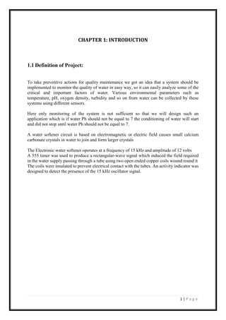
Appendix III: MATLAB Code:
4 clear all;
5
6 %%Variables (Edit yourself)
7
8 SerialPort='com10'; %serial port
9 MaxDeviation = 14;%Maximum Allowable Change from one value to next
10 TimeInterval=0.2;%time interval between each input.
11 loop=500;%count values
12
13 %%Set up the serial port object
14
15 s = serial(SerialPort)
16 fopen(s);
17 PH =now;
18 Time = 0;
19
20 %% Set up the figure
21
22 figureHandle = figure('NumberTitle','off',...
23 'Name','PH Characteristics',...
24 'Color',[0 0 0],'Visible','off');
25
26 % Set axes
27
28 axesHandle = axes('Parent',figureHandle,...
29 'YGrid','on',...
30 'YColor',[0.9725 0.9725 0.9725],...
31 'XGrid','on',...
32 'XColor',[0.9725 0.9725 0.9725],...
33 'Color',[0 0 0]);
34
35 hold on;
36 plotHandle = plot(axesHandle,PH,Time,'Marker','.','LineWidth',1,'Color',[0 1 0]);
37 xlim(axesHandle,[min(PH) max(PH+0.001)]);
38
39 % Create xlabel
40
41 xlabel('Time','FontWeight','bold','FontSize',14,'Color',[1 1 0]);
42
43 % Create ylabel
44
45 ylabel('PH','FontWeight','bold','FontSize',14,'Color',[1 1 0]);
46
47 % Create title
48
49 title('Real Time Data','FontSize',15,'Color',[1 1 0]);
50
51 %% Initializing variables
52
53 Time(1)=0;
54 PH(1)=0;
55 count = 2;
56 k=1;
57 while ~isequal(count,loop)
58
59 %%Re creating Serial port before timeout
60
61 k=k+1;
62 if k==25](https://image.slidesharecdn.com/wqmcfinalreport513317-161102173202/85/final-report_51_33_17-32-320.jpg)
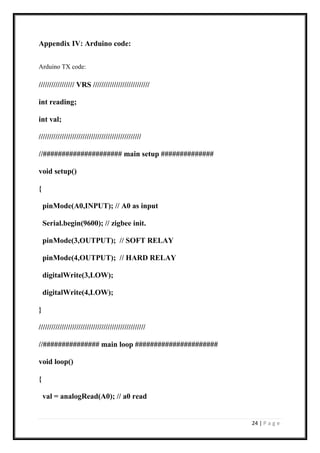
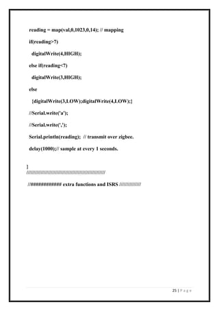
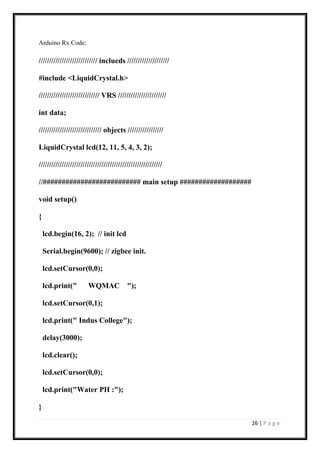
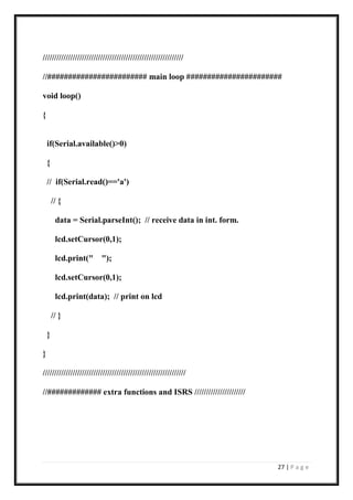


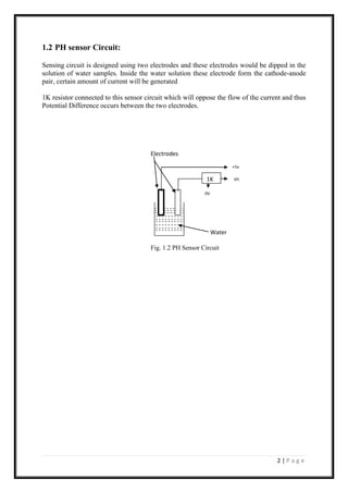
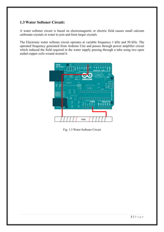
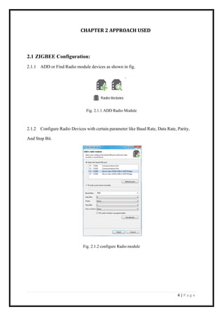
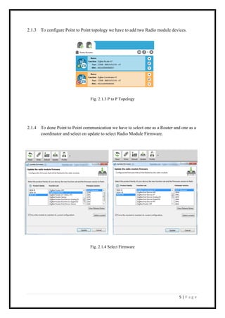
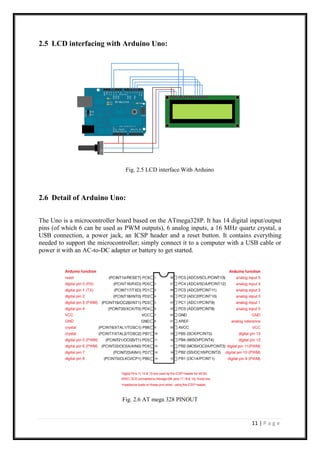
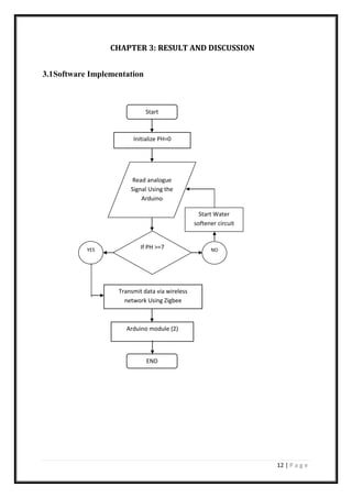
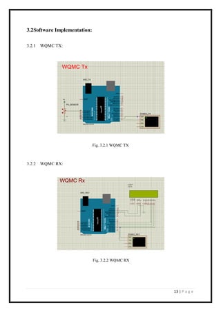
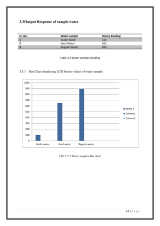
The document presents a project report on a water quality monitoring and conditioning system using wireless sensor network technology, specifically Zigbee, to measure pH levels in water and control water softening. It includes design details for pH sensor circuits, water softener circuits, and the integration of Arduino with MATLAB for data processing. The project concludes with software implementation results and data visualizations, supporting the real-time monitoring and conditioning of water quality.


