Downloaded 220 times


![81
References
[1] http://www.powermin.nic.in,www.vegakitindia.com
[2] Strategic Plan for New and Renewable Energy For the Period 2011-17, A Report by
Ministry of New and Renewable Energy, Government of India, February, 2011.
[3] B.Marion, J. Adelstein, K. Boylen and H. Hayden, “Performance parameters for
grid-connected PV systems”, 31st IEEE Photovoltaics Specialisits Conference and
Exhibition, Lake Buena Vista, Florida
[4] Performance Parameters for Grid-connected PV Systems, NREL Report, February,
2005
[5] S.M. Pietruszko, B. Fetlinski, M. Bialecki, “Analysis of the Perfromance of Grid
Connected Photovoltaic Systems”,photvoltaic Specialists Conference (PVSC),
Philadelphia,June 2009.
[6] Yuzuru Ueda, Kosuke Kurokawa, Takamitsu Itou, Kiyoyuki Kitamura, Yusuke
Miyamoto, Masaharu Yokota, Hiroyuki Sugihara, “Performance Ratio And Yield
Analysis Of Grid Connected Clustered Pv Systems In Japan”IEEE 4th World
Conference on Photovoltaic Energy Conversion, Waikoloa,May 2006.
[7] H. Haeberlin and Ch. Beutler, “Yield of grid connected PV systems in Burgdorf:
Considerably higher than the average yield in Switzerland”, 14th European
Photovoltaic Solar Energy Conference Barcelona (Catalunya), Barcelona Spain, 1997,
p1.
[8] SOLAR PV SYSTEM PERFORMANCE ASSESSMENT GUIDELINE, San Jose
University, California, January, 2012.](https://image.slidesharecdn.com/8thsemthesisee-d-160528105544/85/SOLAR-STREET-LIGHTING-SYSTEM-92-320.jpg)

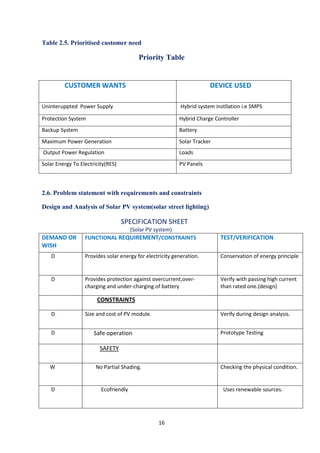
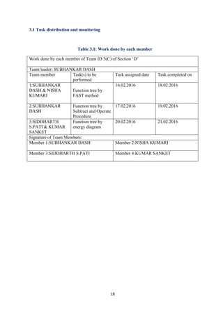
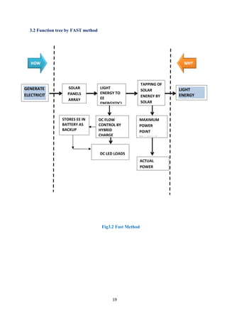
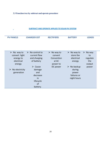
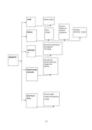
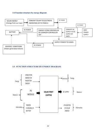
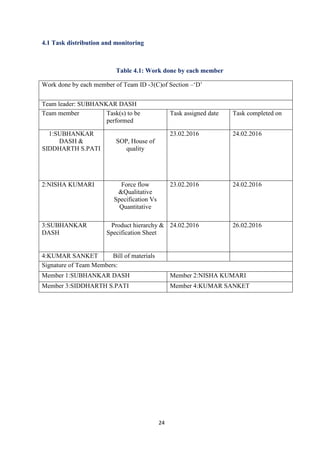
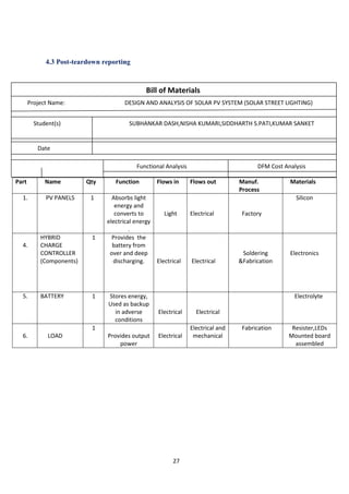
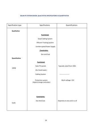
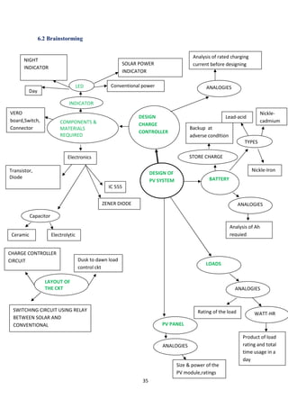
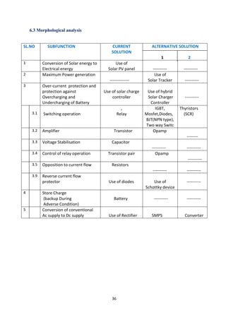
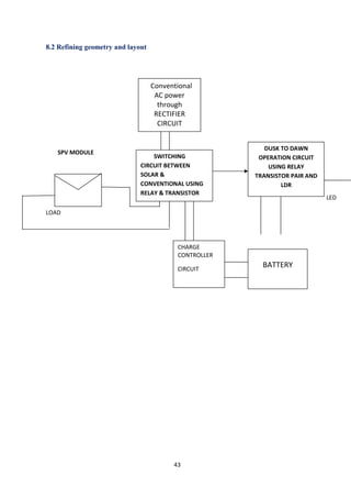
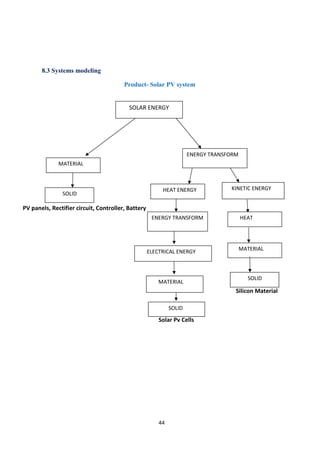
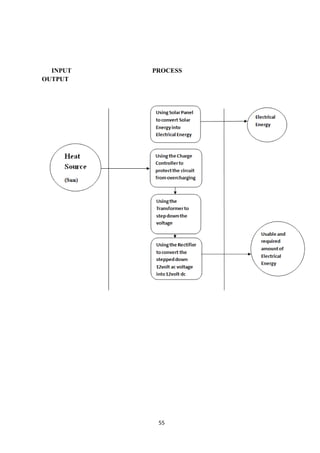
This project report focuses on the design and analysis of a solar photovoltaic (PV) system for street lighting, addressing the need for sustainable energy solutions amidst increasing global energy demands. The report details the components used in the system, including solar panels, charge controllers, and light-dependent resistors, alongside the methodologies for project development and testing. The work was completed by a team of students under the supervision of their faculty, contributing to their Bachelor of Technology degree in electrical engineering.


