SlideShare a Scribd company logo
0
WATER TANK LEVEL DETECTOR
A Project Report
Submitted by
Rahul Bharti (12000510031)
Kumar Ashutosh (12000510058)
Rajnish Kumar (12000510016)
Samir Saurabh (12000510034)
As a partial fulfillment for the award of the degree of Bachelor of Technology in
Electronics and Instrumentation Engineering of West Bengal University of
Technology
Under supervision of
Prof. Chandan Das
Department of Electronics and Instrumentation Engineering
Dr. B. C. Roy Engineering College
Durgapur-713 206
(Affiliated to West Bengal University of Technology)
16th
May, 2014
1
Department of Electronics and Instrumentation Engineering
Dr. B. C. Roy Engineering College, Durgapur
Certificate of approval
Date: May 16, 2014
The report is hereby approved as a bonafide and creditable project work “WATER TANK LEVEL
DETECTOR” carried out and presented by Samir Saurabh (12000510034), Rahul Bharti
(12000510031), Rajnish Kumar (12000510016), Kumar Ashutosh (12000510058) in a manner to
warrant its acceptance as a prerequisite for award of the degree of Bachelor of Technology in
Electronics and Instrumentation Engineering. However, the undersigned do not necessarily endorse or
take responsibility for any statement or opinion expressed or conclusion drawn there in, but only
approve the report for the purpose for which it is submitted.
(Prof. Chandan Das)
Project Supervisor
Countersigned
Head of
Department of Electronics and Instrumentation Engineering
2
ACKNOWLEDGEMENT
The satisfaction and euphoria that accompany the successful completion of any task
would be incomplete without the mention of the people, who made it possible, whose
constant guidance and encouragement aided me in the completion of my project.
I consider it my privilege to express voice of gratitude and respect to all those who
guided me and inspired me in the completion of this project.
I would like to express my thank to Prof. Chandan Das, Dept. of EIE, Dr. B. C. ROY
Engineering College, Durgapur, for his precious guidance & effectually care which
happens to be the psyche of this thesis report.
I would also like to express my heartfelt gratitude to S. K. Chatterjee, HOD of EIE
Department, Dr. B. C. Roy Engineering college, Durgapur, for his continuous
encouragement and valuable guidance.
And of course, nothing could have come true without the support of my family and
friends for their constant external support.
Date: 16.05.2014
Place: Durgapur
3
ABSTRACT
Use of microcontroller will allow to control the whole circuitry and to change the
analog input into digital output. The circuit is fully based on Sensor and Industrial
Instruments so we can applywhole knowledge that we got in 4 years. It detects the level
of the tank immediately and gives the fast response. It uses the transmitter part that
transmit the signal in 2-3 km range.
So our circuit is best suited for industrialuse and also for home appliances.
4
PREFACE
We are the students of EIE 8thsemester are having Technical Report Writing as a part
of our curriculum and have undertaken a project on the “Water Tank Level Detector” .
Through this project we have tried to highlight the importance of “Sensor and
Transducer and Industrial Instruments” .A Sensor is a device that sense the physical
quantity and Transducer change it into electrical one.
5
CONTENTS
Topics Page No.
Certificate of Approval..............................................................................1
Acknowledgement ....................................................................................2
Abstract....................................................................................................3
Preface .....................................................................................................4
Contents ...................................................................................................5
List of Figures...........................................................................................6
Flow of the main bodyof the Project
a. Introduction.....................................................................................7
b. Previous Work................................................................................8
c. Problem Area ..................................................................................9
d. Our Contribution ........................................................................... 10
e. Project Details ............................................................................... 11
f. Results .......................................................................................... 28
g. Conclusion and future scope........................................................... 31
References.............................................................................................. 33
6
LIST OF FIGURE
Topic Page
1. Block Diagram of 16F88.......................................................... 15
2. Internal Memory diagram......................................................... 17
3. Block Diagram MPX 2010 Sensor............................................ 18
4. Output vs Pressure Differential.................................................. 19
5. Unibody Package Cross-sectionDiagram.................................. 20
6. Linearity Specification Comparison.......................................... 21
7. Block Diagram of LM35 with Pin Configuration ....................... 22
8. Pin Configuration of LM 35 ..................................................... 23
9. Graph of LM35........................................................................ 24
10. Circuit Diagram of Project ....................................................... 25
11. Result of Shootof Project......................................................... 28
12. Observation Table of Output .................................................... 29
13. Result in Multimeter Figure...................................................... 30
7
INTRODUCTION
The water level sensor detector is created for measuring the water level
easily and sends the signal to the control room for long range.This has very
simple circuit takes less area.The circuitry consists of 1.5V to 5V voltage
step up circuit, an instrumentation amplifier to read the pressure sensor, a
PIC16F88 I/P microcontroller to convert the analog signal from the pressure
sensor to a digital reading, and a 433MHz RF transmitter to transmit the
water level and battery voltage to a remote base station and computer.
Apart from the use of an 18X PICAXE microcontroller, the circuit is
essentially the same as the “Telemetry” version of the Silicon Chip project.
The transmitted water level and battery voltage is received and displayed on
an indoor base station, as well as being received by another RF receiver and
08M PICAXE built on a breadboard and connected to a PC, which stores the
level in a database for displaying the water level.
8
PREVIOUS WORK
ln the presence of our mentor Prof. Chandan Das, we have shown our keen interest in
the project. Regarding the project, we have completed 80% of the circuitry and almost
got the output. Some what we faced a few problems, but we have taken it just as an
escalater that gives us a way to get the result.
9
PROBLEM AREA
It is the history that when any person working on some typical matter then he faced
some or more problems as per the matter. Our project is also a typical one that consistof
:-
1. Sensors like MPX2010DP means differential pressure sensor.
2. Microcontroller chip PIC16F88.
3. Comparators.
4. Inductance, Capacitor, Transistor, Resistors, Switches etc.
5. Temperature sensor LM335.
6. BCD switches.
All this components are needed for our project, but availability of all this things may or
may not be possible at a time.
The list of problems and the solution are as:
1. Pressure sensor MPX2010DP is not available in the market. So just applying the 4-20
mA current as an input we check out the result. Pressure sensor converts the differential
pressure into 4-20 mA current.
2. Unavailability of BCD switch is enhance the complexity.
3. LM335 is not available in the market. So we replace it with LM35. The substitute
LM35 work like LM335 if we connect a 80 k resistance in parallel.
4. Programming part of our project is not cleared for us, so this also arises problems for
us.
10
OUR CONTRIBUTION
We have almost completed our project its our contribution, devotion and shows dutiful
nature. We have tried a lot to bagged at the destination and almost we got it. We are
here pointing out some points that shows the keen interest , great contribution in our
project work with our mentor sir.:-
1. After searching out for components, we got 90% of the components and spent some
money to bought all of these.
2. We make a good relationship with our mentor sir Mr. Chandan Das and also with the
whole instrumentation department.
3. We apply our theoretical knowledge in our project that we gain in the last 4 years.
We introduced with no. of instruments and applied theories for individuals.
11
PROJECT DETAILS
It includes:-
1. Operating principle.
2. Operating environment.
3. Circuit diagram.
4. Circuit component.
5. Cost.
6. Safety and security.
7. Assumption.
We are just dealing with all in details one by one.
12
Operating Principle
This circuit mainly operates on the principle of Sensor and Transducers and Industrial
Instrumentation. In our project we use MPX20100P differential pressure transmitter that
works on the principle of “measuring the differences between two or more pressure
applied on the input”. Then that differential pressure is applied on the input of IC
LM324 which is the operational amplifier whose output is many times the input.
Temperature sensor LM335Z is also used in our circuit for temperature compensation.
The temperature sensing range of this sensor is -40 to 100 degree Celsius.
The 433Mhz transmitter module is also used in the circuit that transmit the final signal
to the receiver module.
In this way our project is working.
Operating environment
This circuit should be able to work on the normal temperature and pressure as per the
season. Our device also needs to be able to stand up against wildlife who may take an
interest in it as well as heavy thunderstorms.
13
Circuit Components:
1. MPX20100P Differential Pressure Transmitter.
2. LM335Z Temperature Sensor.
3. LM324 Operational Amplifier IC.
4. BCD Switches.
5. PIC 16F88 Microcontroller IC.
6. IN4004, IN 5819 Diode IC.
7. BC 327 Transistor.
8. RGB-CK.
These all are the major parts of our project.
14
We are here describing the components of our project:
The PIC16F87/88 belongs to the Mid-Range family of the PICmicro® devices. Block
diagrams of the devices are shown in Figure 1-1 and Figure 1-2. These devices contain
features that are new to the PIC16 productline:
• Low-power modes:RC_RUN allows the coreand peripherals to be clocked from
the INTRC, while SEC_RUN allows the coreand peripherals to be clocked from
the low-power Timer.
• Internal RC oscillator with eight selectable frequencies, including 31.25 kHz, 125
kHz, 250 kHz, 500 kHz, 1 MHz, 2 MHz, 4 MHz and 8 MHz. The INTRC can be
configured as a primary or secondaryclock source.
• The Timer1 module current consumption has been greatly reduced from 20 μA
(previous PIC16 devices) to 1.8 μA typical (32 kHz at 2V), which is ideal for
real-time clock applications.
• Extended Watchdog Timer (WDT) that can have a programmable period from 1
ms to 268s. The WDT has its own 16-bit prescaler.
• Two-Speed Start-up: When the oscillator is configured for LP, XT or HS
Oscillator mode, this feature will clock the device from the INTRC while the
oscillator is warming up. This, in turn, will enable almost immediate code
execution.
• Fail-Safe Clock Monitor: This feature will allow the device to continue operation
if the primary or secondaryclock sourcefails by switching over to the INTRC.
• The A/D module has a new register for PIC16 devices named ANSEL. This
register allows easier configuration of analog or digital I/O pins.
15
BLOCK DIAGRAM of 16F88:
16
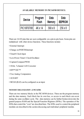
AVAILABLE MEMORY IN PIC16F88 DEVICE:
There are 16 I/O pins that are user configurable on a pin-to-pin basis. Some pins are
multiplexed with other device functions. These functions include:
• External Interrupt
• Change on PORTBInterrupt
• Timer0 Clock Input
• Low-Power Timer1 Clock/Oscillator
• Capture/Compare/PWM
• 10-bit, 7-channel A/D Converter
• SPI™/I2C™
• Two Analog Comparators
• AUSART
• MCLR (RA5) can be configured as an input
MEMORY ORGANIZATION of PIC16F88:
There are two memory blocks in the PIC16F88 devices. These are the program memory
and the data memory. Each block has its own bus, so access to each block can occur
during the same oscillator cycle. The data memory can be further broken down into the
general purpose RAM and the Special Function Registers (SFRs). The operation of the
SFRs that controlthe “core”are described here. The SFRs used to control the peripheral
modules are described in the section discussing each individual peripheral module.
17
The data memory area also contains the data EEPROM memory. This memory is not
directly mapped into the data memory but is indirectly mapped. That is, an indirect
address pointer specifies the address of the data EEPROM memory to read/write. The
PIC16F88 device’s 256 bytes of data EEPROM memory have the address range of 00h-
FFh.
MPX 2010DPPRESSURE SENSOR:
The MPX2010 series silicon piezo resistive pressuresensors provide a very accurate
and linear voltage output — directly proportional to the applied pressure. These sensors
house a single monolithic silicon die with the strain gauge and thin–film resistor
network integrated on each chip. The sensoris laser trimmed for precise span, offset
calibration and temperature compensation.
18
BLOCK DIAGRAM:
Features
 Temperature Compensated over 0°C to +85°C.
 Ratio metric to Supply Voltage.
 Differential and Gauge Options.
Application Examples
• Respiratory Diagnostics.
• Air Movement Control.
• Controllers.
• Pressure Switching.
19
MPX 2010 SERIES RATINGS:
ON–CHIP TEMPERATURECOMPENSATIONand CALIBRATION:
Figure 2 shows the output characteristics of the MPX2010 series at 25°C. The output is
directly proportional to the differential pressure and is essentially a straight line.
The effects of temperature on full scale span and offset are very small and are shown
under Operating Characteristics.
20
Figure 3 illustrates the differential/gauge die in the basic chip carrier. A silicone gel
isolates the die surface and wire bonds from the environment, while allowing the
pressure signal to be transmitted to the silicon diaphragm.
The MPX2010 series pressure sensor operating characteristics and internal reliability
and qualification tests are based on use of dry air as the pressure media. Media other
than dry air may have adverse effects on sensor performance and long term reliability.
Contact the factory for information regarding media compatibility in your application.
LINEARITY
Linearity refers to how well a transducer’s output follows the equation: Vout = Voff +
sensitivity x P over the operating pressure range. There are two basic methods for
calculating nonlinearity: (1) end point straight line fit(2) a least squares best line fit.
While a least squares fit gives the “best case” linearity error (lower numerical value),
the calculations required are burdensome. Conversely, an end point fit will give the
“worst case” error (often more desirable in error budget calculations) and the
calculations are more straightforward for the user. Motorola’s specified pressure sensor
linearity are based on the end point straight line method measured at the midrange
pressure.
21
LM 35 TEMPERATURESENSOR:
The LM35 series are precision integrated-circuit 2 temperature sensors, with an output
voltage linearly proportional to the Centigrade temperature. Thus the LM35 has an
advantage over linear temperature sensors calibrated in ° Kelvin, as the user is not
required to subtract a large constant voltage from the output to obtain convenient
Centigrade scaling. LM35 does not require any external calibration of trimming to
provide typical accuracies of ±¼°C at room temperature and ±¾°C over a full −55°C to
+150°C temperature range. Low cost is assured by trimming and calibration at the
wafer level. The low output impedance, linear output, and precise inherent calibration of
the LM35 make interfacing to readout or control circuitry especially easy. The device is
used with single power supplies, or with plus and minus supplies. As the LM35 draws
only 60 micro A from the supply, it has very low self-heating of less than 0.1°C in still
air. The LM35 is rated to operate over a −55°C to +150°C temperature range, while the
LM35C is rated for a −40°C to +110°C range (−10° with improved accuracy). The
LM35 series is available packaged in hermetic TO transistor packages, while the
LM35C, LM35CA, and LM35D are also available in the plastic TO-92 transistor
package. The LM35D is also available in an 8-lead surface-mount small outline package
and a plastic TO-220 package.
22
BLOCK DIAGRAM:
Both the above figure is of LM 35.
23
OP AMP LM 324:
The LM124-N series consists of four independent, high gain, internally frequency
compensated operational amplifiers which were designed specifically to operate from a
single power supply over a wide range of voltages. Operation from split power supplies
is also possible and the low power supply current drain is independent of the magnitude
of the power supply voltage.
BLOCK DIAGRAM:
24
GRAPH OF LM 324:
25
Circuit Diagram:
26
COST
Since different water sensors are already in use but most of them have
higher costs. So our projects must have cost effective.
The total expenditure is about 1500/- Rs. on our project.
Safety and security
This device shall not transmit harmful electromagnetic radiation and shall
protect against any materials considered harmful to the environment.
Batteries and other components without harmful chemicals have been a
requirement of this project.All components placed directly in the river or
well shall not interfere with safe navigation of said river or stream by
paddlers or boaters.
All components shall be protected from the environment and shall be
contained in waterproof, environmentally robust, structures. Any external
wiring or cables shall be shielded as appropriate and frayed or damaged
cables shall not be used. Since the device will be placed out
side in a natural environment, the system shall not make any impact on the
local habitat which it is placed.
27
Assumption
One assumption the team has made is that the device will not be tampered
with after it is installed except by the owner.
Another assumption is that the device will be installed in an area that has cell
coverage with a directional antenna. The device will not work in the most
remote areas where there is no cell coverage.
28
RESULT
After completion of our project, we got enumeras wind up from this. Lack of pressure
sensor increase our complexity but giving the input 4-20 mA current we notched at the
important result, that we are going to discuss here:
Our ckt gives good response for the current range 4-20mA.
When changing the input, ckt respond well. For the sake of complexiety, we used 3
LED's namely red, green and blue. Red glows for 20 mA current, Blue for 12 mA and
Green for 4mA.
29
OBSERVATION TABLE
We got the output voltage(mV) of the selfmade circuit when we provide the input
current(mA):-
30
When we change the input current, multimeter shows deflection across comparator
circuit:
In this way we got the result.
31
FUTURE TRENDS
Considering the advantages and disadvantages of this circuit, characteristics
of the project limited the use in industries in the future:-
1. In the industrial area this circuit reduces the complexity of the system
because this is wireless.
2. Home appliances: our circuit has the limited range. That is why this circuit
can better be suited in our home.
3. This circuit does not works in the remote area. So in our future we will try
to overcome of this difficulties.
32
CONCLUSION
After applying the basic ideas in our project, we found out some typical and
noteworthy pionts that are given as:
1. This circuitry only works for small or limited range.
2. The circuit consists of a temperature sensor that can work for the range -
40-100 degree C.
3. All components shall be protected from the environment and shall be
contained in waterproof, environmentally robust, structures.
4. The team’s largest risk is that our pressure sensor will not be able to
measure the water level accurately enough. This could be due to tubing
getting damaged when frozen over winter or pressure leaking from the
pressure chamber. To mitigate this risk we have chosen a backup way of
measuring the water level. This way if the pressure sensor doesn’t work, we
will not have to start from scratch.
33
References
1.http://www.google.co.in2
2.http://www.ceb.utk.edu
3.http://www.wikkipedia.com

More Related Content

What's hot

SPORT TOURNAMENT MANAGMENT SYSTEM (STMS)
SPORT TOURNAMENT MANAGMENT SYSTEM (STMS)SPORT TOURNAMENT MANAGMENT SYSTEM (STMS)
SPORT TOURNAMENT MANAGMENT SYSTEM (STMS)
Dilip Prajapati
 
Sample_report_for_MINI_PROJECT.docx (1).pdf
Sample_report_for_MINI_PROJECT.docx (1).pdfSample_report_for_MINI_PROJECT.docx (1).pdf
Sample_report_for_MINI_PROJECT.docx (1).pdf
EkagraGupta1
 
Online tour and travel PPT
Online tour and travel PPTOnline tour and travel PPT
Online tour and travel PPT
Gobinda Karmakar ☁
 
Virtual Reality Technology.pptx
Virtual Reality Technology.pptxVirtual Reality Technology.pptx
Virtual Reality Technology.pptx
LSURYAPRAKASHREDDY
 
Introduction to Unity
Introduction to UnityIntroduction to Unity
Introduction to Unity
University of Auckland
 
B.Sc.CSIT final year(7th semester) project on Tenant Screening
B.Sc.CSIT final year(7th semester) project on Tenant ScreeningB.Sc.CSIT final year(7th semester) project on Tenant Screening
B.Sc.CSIT final year(7th semester) project on Tenant Screening
Urgen Sherpa
 
Zombi - Shoot for Survive
Zombi - Shoot for SurviveZombi - Shoot for Survive
Zombi - Shoot for Survive
Divy Singh Rathore
 
Android app development ppt
Android app development pptAndroid app development ppt
Android app development ppt
saitej15
 
Introduction to game development
Introduction to game developmentIntroduction to game development
Introduction to game development
Abdelrahman Ahmed
 
Android College Application Project Report
Android College Application Project ReportAndroid College Application Project Report
Android College Application Project Report
stalin george
 
Virtual Tour Introduction
Virtual Tour IntroductionVirtual Tour Introduction
Virtual Tour IntroductionDian Novita
 
Snake game implementation in c
Snake game implementation in cSnake game implementation in c
Snake game implementation in c
Upendra Sengar
 
Report on car racing game for android
Report on car racing game for androidReport on car racing game for android
Report on car racing game for android
ravijot singh
 
Event Management System Document
Event Management System Document Event Management System Document
Event Management System Document LJ PROJECTS
 
Android Programming Basics
Android Programming BasicsAndroid Programming Basics
Android Programming Basics
Eueung Mulyana
 
Hotel management report
Hotel management reportHotel management report
Hotel management report
Nishant Bhardwaj
 
INTRODUCTION TO FLUTTER.pdf
INTRODUCTION TO FLUTTER.pdfINTRODUCTION TO FLUTTER.pdf
INTRODUCTION TO FLUTTER.pdf
AdarshMathuri
 
Introduction to Android Development
Introduction to Android DevelopmentIntroduction to Android Development
Introduction to Android Development
Aly Abdelkareem
 
Presentation Virtual Reality and CAD
Presentation Virtual Reality and CADPresentation Virtual Reality and CAD
Presentation Virtual Reality and CAD
ontor omi
 

What's hot (20)

SPORT TOURNAMENT MANAGMENT SYSTEM (STMS)
SPORT TOURNAMENT MANAGMENT SYSTEM (STMS)SPORT TOURNAMENT MANAGMENT SYSTEM (STMS)
SPORT TOURNAMENT MANAGMENT SYSTEM (STMS)
 
Sample_report_for_MINI_PROJECT.docx (1).pdf
Sample_report_for_MINI_PROJECT.docx (1).pdfSample_report_for_MINI_PROJECT.docx (1).pdf
Sample_report_for_MINI_PROJECT.docx (1).pdf
 
Online tour and travel PPT
Online tour and travel PPTOnline tour and travel PPT
Online tour and travel PPT
 
Virtual Reality Technology.pptx
Virtual Reality Technology.pptxVirtual Reality Technology.pptx
Virtual Reality Technology.pptx
 
Introduction to Unity
Introduction to UnityIntroduction to Unity
Introduction to Unity
 
B.Sc.CSIT final year(7th semester) project on Tenant Screening
B.Sc.CSIT final year(7th semester) project on Tenant ScreeningB.Sc.CSIT final year(7th semester) project on Tenant Screening
B.Sc.CSIT final year(7th semester) project on Tenant Screening
 
Zombi - Shoot for Survive
Zombi - Shoot for SurviveZombi - Shoot for Survive
Zombi - Shoot for Survive
 
Android app development ppt
Android app development pptAndroid app development ppt
Android app development ppt
 
UNIT CONVERTER
UNIT CONVERTERUNIT CONVERTER
UNIT CONVERTER
 
Introduction to game development
Introduction to game developmentIntroduction to game development
Introduction to game development
 
Android College Application Project Report
Android College Application Project ReportAndroid College Application Project Report
Android College Application Project Report
 
Virtual Tour Introduction
Virtual Tour IntroductionVirtual Tour Introduction
Virtual Tour Introduction
 
Snake game implementation in c
Snake game implementation in cSnake game implementation in c
Snake game implementation in c
 
Report on car racing game for android
Report on car racing game for androidReport on car racing game for android
Report on car racing game for android
 
Event Management System Document
Event Management System Document Event Management System Document
Event Management System Document
 
Android Programming Basics
Android Programming BasicsAndroid Programming Basics
Android Programming Basics
 
Hotel management report
Hotel management reportHotel management report
Hotel management report
 
INTRODUCTION TO FLUTTER.pdf
INTRODUCTION TO FLUTTER.pdfINTRODUCTION TO FLUTTER.pdf
INTRODUCTION TO FLUTTER.pdf
 
Introduction to Android Development
Introduction to Android DevelopmentIntroduction to Android Development
Introduction to Android Development
 
Presentation Virtual Reality and CAD
Presentation Virtual Reality and CADPresentation Virtual Reality and CAD
Presentation Virtual Reality and CAD
 

Viewers also liked

Energy Audit A Case Study of Pashupati Candle filter Udhyog And Country foo...
Energy Audit A Case Study of Pashupati Candle filter Udhyog  And  Country foo...Energy Audit A Case Study of Pashupati Candle filter Udhyog  And  Country foo...
Energy Audit A Case Study of Pashupati Candle filter Udhyog And Country foo...
Bikram Dahal
 
GSM BASED e-NOTICE BOARD final year project report
GSM BASED e-NOTICE BOARD final year project reportGSM BASED e-NOTICE BOARD final year project report
GSM BASED e-NOTICE BOARD final year project reportVenkatesh Agnihotri
 
Final year project on Remote Infrastructure Management
Final year project on Remote Infrastructure ManagementFinal year project on Remote Infrastructure Management
Final year project on Remote Infrastructure Management
jairaman
 
Basic Datalogger Water Level Measurement
Basic Datalogger Water Level MeasurementBasic Datalogger Water Level Measurement
Basic Datalogger Water Level Measurement
HydroG Resources
 
Car Game - Final Year Project
Car Game - Final Year ProjectCar Game - Final Year Project
Car Game - Final Year ProjectVivek Naskar
 
Deep drilling - Risks and challenges with examples from the German Molasse Basin
Deep drilling - Risks and challenges with examples from the German Molasse BasinDeep drilling - Risks and challenges with examples from the German Molasse Basin
Deep drilling - Risks and challenges with examples from the German Molasse BasinGerd Tarand
 
Waterlevelindicator
WaterlevelindicatorWaterlevelindicator
Waterlevelindicator
Shubhi Verma
 
Final Year Project Report Device Control using sms
Final Year Project Report Device Control using smsFinal Year Project Report Device Control using sms
Final Year Project Report Device Control using smsMuhammad Shakeel
 
Water level indicator by bhushan kumbhalkar
Water level indicator by  bhushan kumbhalkarWater level indicator by  bhushan kumbhalkar
Water level indicator by bhushan kumbhalkar
Bhushan Kumbhalkar
 
Mobile phone detector pdf
Mobile phone detector pdfMobile phone detector pdf
Mobile phone detector pdf
Vamshi Varun
 
Science fair and exhibitions
Science fair and exhibitionsScience fair and exhibitions
Science fair and exhibitions
arunrsr6
 
summer training project
 summer training project summer training project
summer training projectandyknp2012
 
Internship report Of Final Professin DVM
Internship report Of Final Professin DVMInternship report Of Final Professin DVM
Internship report Of Final Professin DVMSyed Tanveer Shah
 
Final Year Project Report Of Pgdm 6th Trimester
Final Year Project Report Of Pgdm 6th TrimesterFinal Year Project Report Of Pgdm 6th Trimester
Final Year Project Report Of Pgdm 6th Trimester
towardsgoal
 
Zeeshan Ali Khan B.Sc-Interior Design(Residential Design Project)
Zeeshan Ali Khan B.Sc-Interior Design(Residential Design Project)Zeeshan Ali Khan B.Sc-Interior Design(Residential Design Project)
Zeeshan Ali Khan B.Sc-Interior Design(Residential Design Project)
dezyneecole
 
VTU PG Program-M.Tech Project Report Format
 VTU PG Program-M.Tech Project Report Format VTU PG Program-M.Tech Project Report Format
VTU PG Program-M.Tech Project Report FormatDrBBS Kumar
 
Project report of Cell phone detector circuit
Project report of Cell phone detector circuitProject report of Cell phone detector circuit
Project report of Cell phone detector circuitMoin Aman
 
Fuel tracking system
Fuel tracking systemFuel tracking system
Fuel tracking system
VAMO SYSTEMS PRIVATE LIMITED
 
MINI PROJECT ON CELLPHONE DETECTOR
MINI PROJECT ON CELLPHONE DETECTORMINI PROJECT ON CELLPHONE DETECTOR
MINI PROJECT ON CELLPHONE DETECTOR
Prannoy Chakravarthi
 
water level indicator alarm
water level indicator alarmwater level indicator alarm
water level indicator alarmAnish Anand
 

Viewers also liked (20)

Energy Audit A Case Study of Pashupati Candle filter Udhyog And Country foo...
Energy Audit A Case Study of Pashupati Candle filter Udhyog  And  Country foo...Energy Audit A Case Study of Pashupati Candle filter Udhyog  And  Country foo...
Energy Audit A Case Study of Pashupati Candle filter Udhyog And Country foo...
 
GSM BASED e-NOTICE BOARD final year project report
GSM BASED e-NOTICE BOARD final year project reportGSM BASED e-NOTICE BOARD final year project report
GSM BASED e-NOTICE BOARD final year project report
 
Final year project on Remote Infrastructure Management
Final year project on Remote Infrastructure ManagementFinal year project on Remote Infrastructure Management
Final year project on Remote Infrastructure Management
 
Basic Datalogger Water Level Measurement
Basic Datalogger Water Level MeasurementBasic Datalogger Water Level Measurement
Basic Datalogger Water Level Measurement
 
Car Game - Final Year Project
Car Game - Final Year ProjectCar Game - Final Year Project
Car Game - Final Year Project
 
Deep drilling - Risks and challenges with examples from the German Molasse Basin
Deep drilling - Risks and challenges with examples from the German Molasse BasinDeep drilling - Risks and challenges with examples from the German Molasse Basin
Deep drilling - Risks and challenges with examples from the German Molasse Basin
 
Waterlevelindicator
WaterlevelindicatorWaterlevelindicator
Waterlevelindicator
 
Final Year Project Report Device Control using sms
Final Year Project Report Device Control using smsFinal Year Project Report Device Control using sms
Final Year Project Report Device Control using sms
 
Water level indicator by bhushan kumbhalkar
Water level indicator by  bhushan kumbhalkarWater level indicator by  bhushan kumbhalkar
Water level indicator by bhushan kumbhalkar
 
Mobile phone detector pdf
Mobile phone detector pdfMobile phone detector pdf
Mobile phone detector pdf
 
Science fair and exhibitions
Science fair and exhibitionsScience fair and exhibitions
Science fair and exhibitions
 
summer training project
 summer training project summer training project
summer training project
 
Internship report Of Final Professin DVM
Internship report Of Final Professin DVMInternship report Of Final Professin DVM
Internship report Of Final Professin DVM
 
Final Year Project Report Of Pgdm 6th Trimester
Final Year Project Report Of Pgdm 6th TrimesterFinal Year Project Report Of Pgdm 6th Trimester
Final Year Project Report Of Pgdm 6th Trimester
 
Zeeshan Ali Khan B.Sc-Interior Design(Residential Design Project)
Zeeshan Ali Khan B.Sc-Interior Design(Residential Design Project)Zeeshan Ali Khan B.Sc-Interior Design(Residential Design Project)
Zeeshan Ali Khan B.Sc-Interior Design(Residential Design Project)
 
VTU PG Program-M.Tech Project Report Format
 VTU PG Program-M.Tech Project Report Format VTU PG Program-M.Tech Project Report Format
VTU PG Program-M.Tech Project Report Format
 
Project report of Cell phone detector circuit
Project report of Cell phone detector circuitProject report of Cell phone detector circuit
Project report of Cell phone detector circuit
 
Fuel tracking system
Fuel tracking systemFuel tracking system
Fuel tracking system
 
MINI PROJECT ON CELLPHONE DETECTOR
MINI PROJECT ON CELLPHONE DETECTORMINI PROJECT ON CELLPHONE DETECTOR
MINI PROJECT ON CELLPHONE DETECTOR
 
water level indicator alarm
water level indicator alarmwater level indicator alarm
water level indicator alarm
 

Similar to Final year project

Schneider Report
Schneider ReportSchneider Report
Schneider ReportShiraz Khan
 
E Assistance for Elderly and Disabled Part 1
E Assistance for Elderly and Disabled Part 1E Assistance for Elderly and Disabled Part 1
E Assistance for Elderly and Disabled Part 1NISHANT SHRISTIRAJ
 
Traing report
Traing reportTraing report
Traing report
Manoj Singh Rao
 
report.pdf
report.pdfreport.pdf
report.pdf
KarnaPatel17
 
final report_51_33_17
final report_51_33_17final report_51_33_17
final report_51_33_17
Darshil Shah
 
Automatic liquid filling and mixing process using PLC
Automatic liquid filling and mixing process using PLCAutomatic liquid filling and mixing process using PLC
Automatic liquid filling and mixing process using PLC
AMIT KUMAR SINGH
 
Temperature_Controlled_DC_Fan_Using_Ther.docx
Temperature_Controlled_DC_Fan_Using_Ther.docxTemperature_Controlled_DC_Fan_Using_Ther.docx
Temperature_Controlled_DC_Fan_Using_Ther.docx
Yadav Raj
 
Schneider Electric Internship report
Schneider Electric Internship reportSchneider Electric Internship report
Schneider Electric Internship report
M Nadeem
 
WIRELESS ROBOT
WIRELESS ROBOTWIRELESS ROBOT
WIRELESS ROBOT
AIRTEL
 
Automatic power factor_detection_and_cor
Automatic power factor_detection_and_corAutomatic power factor_detection_and_cor
Automatic power factor_detection_and_cor
hadafree
 
Minor Project Report: Automatic Door Control System
Minor Project Report: Automatic Door Control SystemMinor Project Report: Automatic Door Control System
Minor Project Report: Automatic Door Control System
Saban Kumar K.C.
 
IRJET- IoT based Pretreatment Process Monitoring
IRJET-  	  IoT based Pretreatment Process MonitoringIRJET-  	  IoT based Pretreatment Process Monitoring
IRJET- IoT based Pretreatment Process Monitoring
IRJET Journal
 
DC-injection Braking
DC-injection BrakingDC-injection Braking
DC-injection Braking
Arun Thapa
 
Obstacle Avoiding Robot Report Robot23
Obstacle Avoiding Robot Report Robot23Obstacle Avoiding Robot Report Robot23
Obstacle Avoiding Robot Report Robot23Abhijeet kapse
 
AC fan speed control using remote control power electronics term project report
 AC fan speed control using remote control power electronics term project report AC fan speed control using remote control power electronics term project report
AC fan speed control using remote control power electronics term project report
Kramat ullah
 

Similar to Final year project (20)

Schneider Report
Schneider ReportSchneider Report
Schneider Report
 
E Assistance for Elderly and Disabled Part 1
E Assistance for Elderly and Disabled Part 1E Assistance for Elderly and Disabled Part 1
E Assistance for Elderly and Disabled Part 1
 
Traing report
Traing reportTraing report
Traing report
 
report.pdf
report.pdfreport.pdf
report.pdf
 
SEM 6th final 1
SEM 6th final 1SEM 6th final 1
SEM 6th final 1
 
THESIS
THESISTHESIS
THESIS
 
final report_51_33_17
final report_51_33_17final report_51_33_17
final report_51_33_17
 
Automatic liquid filling and mixing process using PLC
Automatic liquid filling and mixing process using PLCAutomatic liquid filling and mixing process using PLC
Automatic liquid filling and mixing process using PLC
 
Temperature_Controlled_DC_Fan_Using_Ther.docx
Temperature_Controlled_DC_Fan_Using_Ther.docxTemperature_Controlled_DC_Fan_Using_Ther.docx
Temperature_Controlled_DC_Fan_Using_Ther.docx
 
final report.pdf
final report.pdffinal report.pdf
final report.pdf
 
Schneider Electric Internship report
Schneider Electric Internship reportSchneider Electric Internship report
Schneider Electric Internship report
 
WIRELESS ROBOT
WIRELESS ROBOTWIRELESS ROBOT
WIRELESS ROBOT
 
Automatic power factor_detection_and_cor
Automatic power factor_detection_and_corAutomatic power factor_detection_and_cor
Automatic power factor_detection_and_cor
 
chandan
chandanchandan
chandan
 
Minor Project Report: Automatic Door Control System
Minor Project Report: Automatic Door Control SystemMinor Project Report: Automatic Door Control System
Minor Project Report: Automatic Door Control System
 
IRJET- IoT based Pretreatment Process Monitoring
IRJET-  	  IoT based Pretreatment Process MonitoringIRJET-  	  IoT based Pretreatment Process Monitoring
IRJET- IoT based Pretreatment Process Monitoring
 
DC-injection Braking
DC-injection BrakingDC-injection Braking
DC-injection Braking
 
Resume_Sunil kumar Singh
Resume_Sunil kumar SinghResume_Sunil kumar Singh
Resume_Sunil kumar Singh
 
Obstacle Avoiding Robot Report Robot23
Obstacle Avoiding Robot Report Robot23Obstacle Avoiding Robot Report Robot23
Obstacle Avoiding Robot Report Robot23
 
AC fan speed control using remote control power electronics term project report
 AC fan speed control using remote control power electronics term project report AC fan speed control using remote control power electronics term project report
AC fan speed control using remote control power electronics term project report
 

Recently uploaded

Pile Foundation by Venkatesh Taduvai (Sub Geotechnical Engineering II)-conver...
Pile Foundation by Venkatesh Taduvai (Sub Geotechnical Engineering II)-conver...Pile Foundation by Venkatesh Taduvai (Sub Geotechnical Engineering II)-conver...
Pile Foundation by Venkatesh Taduvai (Sub Geotechnical Engineering II)-conver...
AJAYKUMARPUND1
 
Industrial Training at Shahjalal Fertilizer Company Limited (SFCL)
Industrial Training at Shahjalal Fertilizer Company Limited (SFCL)Industrial Training at Shahjalal Fertilizer Company Limited (SFCL)
Industrial Training at Shahjalal Fertilizer Company Limited (SFCL)
MdTanvirMahtab2
 
Investor-Presentation-Q1FY2024 investor presentation document.pptx
Investor-Presentation-Q1FY2024 investor presentation document.pptxInvestor-Presentation-Q1FY2024 investor presentation document.pptx
Investor-Presentation-Q1FY2024 investor presentation document.pptx
AmarGB2
 
Runway Orientation Based on the Wind Rose Diagram.pptx
Runway Orientation Based on the Wind Rose Diagram.pptxRunway Orientation Based on the Wind Rose Diagram.pptx
Runway Orientation Based on the Wind Rose Diagram.pptx
SupreethSP4
 
J.Yang, ICLR 2024, MLILAB, KAIST AI.pdf
J.Yang,  ICLR 2024, MLILAB, KAIST AI.pdfJ.Yang,  ICLR 2024, MLILAB, KAIST AI.pdf
J.Yang, ICLR 2024, MLILAB, KAIST AI.pdf
MLILAB
 
Student information management system project report ii.pdf
Student information management system project report ii.pdfStudent information management system project report ii.pdf
Student information management system project report ii.pdf
Kamal Acharya
 
Railway Signalling Principles Edition 3.pdf
Railway Signalling Principles Edition 3.pdfRailway Signalling Principles Edition 3.pdf
Railway Signalling Principles Edition 3.pdf
TeeVichai
 
Planning Of Procurement o different goods and services
Planning Of Procurement o different goods and servicesPlanning Of Procurement o different goods and services
Planning Of Procurement o different goods and services
JoytuBarua2
 
Hybrid optimization of pumped hydro system and solar- Engr. Abdul-Azeez.pdf
Hybrid optimization of pumped hydro system and solar- Engr. Abdul-Azeez.pdfHybrid optimization of pumped hydro system and solar- Engr. Abdul-Azeez.pdf
Hybrid optimization of pumped hydro system and solar- Engr. Abdul-Azeez.pdf
fxintegritypublishin
 
Hierarchical Digital Twin of a Naval Power System
Hierarchical Digital Twin of a Naval Power SystemHierarchical Digital Twin of a Naval Power System
Hierarchical Digital Twin of a Naval Power System
Kerry Sado
 
Nuclear Power Economics and Structuring 2024
Nuclear Power Economics and Structuring 2024Nuclear Power Economics and Structuring 2024
Nuclear Power Economics and Structuring 2024
Massimo Talia
 
AKS UNIVERSITY Satna Final Year Project By OM Hardaha.pdf
AKS UNIVERSITY Satna Final Year Project By OM Hardaha.pdfAKS UNIVERSITY Satna Final Year Project By OM Hardaha.pdf
AKS UNIVERSITY Satna Final Year Project By OM Hardaha.pdf
SamSarthak3
 
space technology lecture notes on satellite
space technology lecture notes on satellitespace technology lecture notes on satellite
space technology lecture notes on satellite
ongomchris
 
ethical hacking in wireless-hacking1.ppt
ethical hacking in wireless-hacking1.pptethical hacking in wireless-hacking1.ppt
ethical hacking in wireless-hacking1.ppt
Jayaprasanna4
 
DESIGN A COTTON SEED SEPARATION MACHINE.docx
DESIGN A COTTON SEED SEPARATION MACHINE.docxDESIGN A COTTON SEED SEPARATION MACHINE.docx
DESIGN A COTTON SEED SEPARATION MACHINE.docx
FluxPrime1
 
一比一原版(IIT毕业证)伊利诺伊理工大学毕业证成绩单专业办理
一比一原版(IIT毕业证)伊利诺伊理工大学毕业证成绩单专业办理一比一原版(IIT毕业证)伊利诺伊理工大学毕业证成绩单专业办理
一比一原版(IIT毕业证)伊利诺伊理工大学毕业证成绩单专业办理
zwunae
 
Gen AI Study Jams _ For the GDSC Leads in India.pdf
Gen AI Study Jams _ For the GDSC Leads in India.pdfGen AI Study Jams _ For the GDSC Leads in India.pdf
Gen AI Study Jams _ For the GDSC Leads in India.pdf
gdsczhcet
 
Design and Analysis of Algorithms-DP,Backtracking,Graphs,B&B
Design and Analysis of Algorithms-DP,Backtracking,Graphs,B&BDesign and Analysis of Algorithms-DP,Backtracking,Graphs,B&B
Design and Analysis of Algorithms-DP,Backtracking,Graphs,B&B
Sreedhar Chowdam
 
Fundamentals of Electric Drives and its applications.pptx
Fundamentals of Electric Drives and its applications.pptxFundamentals of Electric Drives and its applications.pptx
Fundamentals of Electric Drives and its applications.pptx
manasideore6
 
RAT: Retrieval Augmented Thoughts Elicit Context-Aware Reasoning in Long-Hori...
RAT: Retrieval Augmented Thoughts Elicit Context-Aware Reasoning in Long-Hori...RAT: Retrieval Augmented Thoughts Elicit Context-Aware Reasoning in Long-Hori...
RAT: Retrieval Augmented Thoughts Elicit Context-Aware Reasoning in Long-Hori...
thanhdowork
 

Recently uploaded (20)

Pile Foundation by Venkatesh Taduvai (Sub Geotechnical Engineering II)-conver...
Pile Foundation by Venkatesh Taduvai (Sub Geotechnical Engineering II)-conver...Pile Foundation by Venkatesh Taduvai (Sub Geotechnical Engineering II)-conver...
Pile Foundation by Venkatesh Taduvai (Sub Geotechnical Engineering II)-conver...
 
Industrial Training at Shahjalal Fertilizer Company Limited (SFCL)
Industrial Training at Shahjalal Fertilizer Company Limited (SFCL)Industrial Training at Shahjalal Fertilizer Company Limited (SFCL)
Industrial Training at Shahjalal Fertilizer Company Limited (SFCL)
 
Investor-Presentation-Q1FY2024 investor presentation document.pptx
Investor-Presentation-Q1FY2024 investor presentation document.pptxInvestor-Presentation-Q1FY2024 investor presentation document.pptx
Investor-Presentation-Q1FY2024 investor presentation document.pptx
 
Runway Orientation Based on the Wind Rose Diagram.pptx
Runway Orientation Based on the Wind Rose Diagram.pptxRunway Orientation Based on the Wind Rose Diagram.pptx
Runway Orientation Based on the Wind Rose Diagram.pptx
 
J.Yang, ICLR 2024, MLILAB, KAIST AI.pdf
J.Yang,  ICLR 2024, MLILAB, KAIST AI.pdfJ.Yang,  ICLR 2024, MLILAB, KAIST AI.pdf
J.Yang, ICLR 2024, MLILAB, KAIST AI.pdf
 
Student information management system project report ii.pdf
Student information management system project report ii.pdfStudent information management system project report ii.pdf
Student information management system project report ii.pdf
 
Railway Signalling Principles Edition 3.pdf
Railway Signalling Principles Edition 3.pdfRailway Signalling Principles Edition 3.pdf
Railway Signalling Principles Edition 3.pdf
 
Planning Of Procurement o different goods and services
Planning Of Procurement o different goods and servicesPlanning Of Procurement o different goods and services
Planning Of Procurement o different goods and services
 
Hybrid optimization of pumped hydro system and solar- Engr. Abdul-Azeez.pdf
Hybrid optimization of pumped hydro system and solar- Engr. Abdul-Azeez.pdfHybrid optimization of pumped hydro system and solar- Engr. Abdul-Azeez.pdf
Hybrid optimization of pumped hydro system and solar- Engr. Abdul-Azeez.pdf
 
Hierarchical Digital Twin of a Naval Power System
Hierarchical Digital Twin of a Naval Power SystemHierarchical Digital Twin of a Naval Power System
Hierarchical Digital Twin of a Naval Power System
 
Nuclear Power Economics and Structuring 2024
Nuclear Power Economics and Structuring 2024Nuclear Power Economics and Structuring 2024
Nuclear Power Economics and Structuring 2024
 
AKS UNIVERSITY Satna Final Year Project By OM Hardaha.pdf
AKS UNIVERSITY Satna Final Year Project By OM Hardaha.pdfAKS UNIVERSITY Satna Final Year Project By OM Hardaha.pdf
AKS UNIVERSITY Satna Final Year Project By OM Hardaha.pdf
 
space technology lecture notes on satellite
space technology lecture notes on satellitespace technology lecture notes on satellite
space technology lecture notes on satellite
 
ethical hacking in wireless-hacking1.ppt
ethical hacking in wireless-hacking1.pptethical hacking in wireless-hacking1.ppt
ethical hacking in wireless-hacking1.ppt
 
DESIGN A COTTON SEED SEPARATION MACHINE.docx
DESIGN A COTTON SEED SEPARATION MACHINE.docxDESIGN A COTTON SEED SEPARATION MACHINE.docx
DESIGN A COTTON SEED SEPARATION MACHINE.docx
 
一比一原版(IIT毕业证)伊利诺伊理工大学毕业证成绩单专业办理
一比一原版(IIT毕业证)伊利诺伊理工大学毕业证成绩单专业办理一比一原版(IIT毕业证)伊利诺伊理工大学毕业证成绩单专业办理
一比一原版(IIT毕业证)伊利诺伊理工大学毕业证成绩单专业办理
 
Gen AI Study Jams _ For the GDSC Leads in India.pdf
Gen AI Study Jams _ For the GDSC Leads in India.pdfGen AI Study Jams _ For the GDSC Leads in India.pdf
Gen AI Study Jams _ For the GDSC Leads in India.pdf
 
Design and Analysis of Algorithms-DP,Backtracking,Graphs,B&B
Design and Analysis of Algorithms-DP,Backtracking,Graphs,B&BDesign and Analysis of Algorithms-DP,Backtracking,Graphs,B&B
Design and Analysis of Algorithms-DP,Backtracking,Graphs,B&B
 
Fundamentals of Electric Drives and its applications.pptx
Fundamentals of Electric Drives and its applications.pptxFundamentals of Electric Drives and its applications.pptx
Fundamentals of Electric Drives and its applications.pptx
 
RAT: Retrieval Augmented Thoughts Elicit Context-Aware Reasoning in Long-Hori...
RAT: Retrieval Augmented Thoughts Elicit Context-Aware Reasoning in Long-Hori...RAT: Retrieval Augmented Thoughts Elicit Context-Aware Reasoning in Long-Hori...
RAT: Retrieval Augmented Thoughts Elicit Context-Aware Reasoning in Long-Hori...
 

Final year project

  • 1. 0 WATER TANK LEVEL DETECTOR A Project Report Submitted by Rahul Bharti (12000510031) Kumar Ashutosh (12000510058) Rajnish Kumar (12000510016) Samir Saurabh (12000510034) As a partial fulfillment for the award of the degree of Bachelor of Technology in Electronics and Instrumentation Engineering of West Bengal University of Technology Under supervision of Prof. Chandan Das Department of Electronics and Instrumentation Engineering Dr. B. C. Roy Engineering College Durgapur-713 206 (Affiliated to West Bengal University of Technology) 16th May, 2014
  • 2. 1 Department of Electronics and Instrumentation Engineering Dr. B. C. Roy Engineering College, Durgapur Certificate of approval Date: May 16, 2014 The report is hereby approved as a bonafide and creditable project work “WATER TANK LEVEL DETECTOR” carried out and presented by Samir Saurabh (12000510034), Rahul Bharti (12000510031), Rajnish Kumar (12000510016), Kumar Ashutosh (12000510058) in a manner to warrant its acceptance as a prerequisite for award of the degree of Bachelor of Technology in Electronics and Instrumentation Engineering. However, the undersigned do not necessarily endorse or take responsibility for any statement or opinion expressed or conclusion drawn there in, but only approve the report for the purpose for which it is submitted. (Prof. Chandan Das) Project Supervisor Countersigned Head of Department of Electronics and Instrumentation Engineering
  • 3. 2 ACKNOWLEDGEMENT The satisfaction and euphoria that accompany the successful completion of any task would be incomplete without the mention of the people, who made it possible, whose constant guidance and encouragement aided me in the completion of my project. I consider it my privilege to express voice of gratitude and respect to all those who guided me and inspired me in the completion of this project. I would like to express my thank to Prof. Chandan Das, Dept. of EIE, Dr. B. C. ROY Engineering College, Durgapur, for his precious guidance & effectually care which happens to be the psyche of this thesis report. I would also like to express my heartfelt gratitude to S. K. Chatterjee, HOD of EIE Department, Dr. B. C. Roy Engineering college, Durgapur, for his continuous encouragement and valuable guidance. And of course, nothing could have come true without the support of my family and friends for their constant external support. Date: 16.05.2014 Place: Durgapur
  • 4. 3 ABSTRACT Use of microcontroller will allow to control the whole circuitry and to change the analog input into digital output. The circuit is fully based on Sensor and Industrial Instruments so we can applywhole knowledge that we got in 4 years. It detects the level of the tank immediately and gives the fast response. It uses the transmitter part that transmit the signal in 2-3 km range. So our circuit is best suited for industrialuse and also for home appliances.
  • 5. 4 PREFACE We are the students of EIE 8thsemester are having Technical Report Writing as a part of our curriculum and have undertaken a project on the “Water Tank Level Detector” . Through this project we have tried to highlight the importance of “Sensor and Transducer and Industrial Instruments” .A Sensor is a device that sense the physical quantity and Transducer change it into electrical one.
  • 6. 5 CONTENTS Topics Page No. Certificate of Approval..............................................................................1 Acknowledgement ....................................................................................2 Abstract....................................................................................................3 Preface .....................................................................................................4 Contents ...................................................................................................5 List of Figures...........................................................................................6 Flow of the main bodyof the Project a. Introduction.....................................................................................7 b. Previous Work................................................................................8 c. Problem Area ..................................................................................9 d. Our Contribution ........................................................................... 10 e. Project Details ............................................................................... 11 f. Results .......................................................................................... 28 g. Conclusion and future scope........................................................... 31 References.............................................................................................. 33
  • 7. 6 LIST OF FIGURE Topic Page 1. Block Diagram of 16F88.......................................................... 15 2. Internal Memory diagram......................................................... 17 3. Block Diagram MPX 2010 Sensor............................................ 18 4. Output vs Pressure Differential.................................................. 19 5. Unibody Package Cross-sectionDiagram.................................. 20 6. Linearity Specification Comparison.......................................... 21 7. Block Diagram of LM35 with Pin Configuration ....................... 22 8. Pin Configuration of LM 35 ..................................................... 23 9. Graph of LM35........................................................................ 24 10. Circuit Diagram of Project ....................................................... 25 11. Result of Shootof Project......................................................... 28 12. Observation Table of Output .................................................... 29 13. Result in Multimeter Figure...................................................... 30
  • 8. 7 INTRODUCTION The water level sensor detector is created for measuring the water level easily and sends the signal to the control room for long range.This has very simple circuit takes less area.The circuitry consists of 1.5V to 5V voltage step up circuit, an instrumentation amplifier to read the pressure sensor, a PIC16F88 I/P microcontroller to convert the analog signal from the pressure sensor to a digital reading, and a 433MHz RF transmitter to transmit the water level and battery voltage to a remote base station and computer. Apart from the use of an 18X PICAXE microcontroller, the circuit is essentially the same as the “Telemetry” version of the Silicon Chip project. The transmitted water level and battery voltage is received and displayed on an indoor base station, as well as being received by another RF receiver and 08M PICAXE built on a breadboard and connected to a PC, which stores the level in a database for displaying the water level.
  • 9. 8 PREVIOUS WORK ln the presence of our mentor Prof. Chandan Das, we have shown our keen interest in the project. Regarding the project, we have completed 80% of the circuitry and almost got the output. Some what we faced a few problems, but we have taken it just as an escalater that gives us a way to get the result.
  • 10. 9 PROBLEM AREA It is the history that when any person working on some typical matter then he faced some or more problems as per the matter. Our project is also a typical one that consistof :- 1. Sensors like MPX2010DP means differential pressure sensor. 2. Microcontroller chip PIC16F88. 3. Comparators. 4. Inductance, Capacitor, Transistor, Resistors, Switches etc. 5. Temperature sensor LM335. 6. BCD switches. All this components are needed for our project, but availability of all this things may or may not be possible at a time. The list of problems and the solution are as: 1. Pressure sensor MPX2010DP is not available in the market. So just applying the 4-20 mA current as an input we check out the result. Pressure sensor converts the differential pressure into 4-20 mA current. 2. Unavailability of BCD switch is enhance the complexity. 3. LM335 is not available in the market. So we replace it with LM35. The substitute LM35 work like LM335 if we connect a 80 k resistance in parallel. 4. Programming part of our project is not cleared for us, so this also arises problems for us.
  • 11. 10 OUR CONTRIBUTION We have almost completed our project its our contribution, devotion and shows dutiful nature. We have tried a lot to bagged at the destination and almost we got it. We are here pointing out some points that shows the keen interest , great contribution in our project work with our mentor sir.:- 1. After searching out for components, we got 90% of the components and spent some money to bought all of these. 2. We make a good relationship with our mentor sir Mr. Chandan Das and also with the whole instrumentation department. 3. We apply our theoretical knowledge in our project that we gain in the last 4 years. We introduced with no. of instruments and applied theories for individuals.
  • 12. 11 PROJECT DETAILS It includes:- 1. Operating principle. 2. Operating environment. 3. Circuit diagram. 4. Circuit component. 5. Cost. 6. Safety and security. 7. Assumption. We are just dealing with all in details one by one.
  • 13. 12 Operating Principle This circuit mainly operates on the principle of Sensor and Transducers and Industrial Instrumentation. In our project we use MPX20100P differential pressure transmitter that works on the principle of “measuring the differences between two or more pressure applied on the input”. Then that differential pressure is applied on the input of IC LM324 which is the operational amplifier whose output is many times the input. Temperature sensor LM335Z is also used in our circuit for temperature compensation. The temperature sensing range of this sensor is -40 to 100 degree Celsius. The 433Mhz transmitter module is also used in the circuit that transmit the final signal to the receiver module. In this way our project is working. Operating environment This circuit should be able to work on the normal temperature and pressure as per the season. Our device also needs to be able to stand up against wildlife who may take an interest in it as well as heavy thunderstorms.
  • 14. 13 Circuit Components: 1. MPX20100P Differential Pressure Transmitter. 2. LM335Z Temperature Sensor. 3. LM324 Operational Amplifier IC. 4. BCD Switches. 5. PIC 16F88 Microcontroller IC. 6. IN4004, IN 5819 Diode IC. 7. BC 327 Transistor. 8. RGB-CK. These all are the major parts of our project.
  • 15. 14 We are here describing the components of our project: The PIC16F87/88 belongs to the Mid-Range family of the PICmicro® devices. Block diagrams of the devices are shown in Figure 1-1 and Figure 1-2. These devices contain features that are new to the PIC16 productline: • Low-power modes:RC_RUN allows the coreand peripherals to be clocked from the INTRC, while SEC_RUN allows the coreand peripherals to be clocked from the low-power Timer. • Internal RC oscillator with eight selectable frequencies, including 31.25 kHz, 125 kHz, 250 kHz, 500 kHz, 1 MHz, 2 MHz, 4 MHz and 8 MHz. The INTRC can be configured as a primary or secondaryclock source. • The Timer1 module current consumption has been greatly reduced from 20 μA (previous PIC16 devices) to 1.8 μA typical (32 kHz at 2V), which is ideal for real-time clock applications. • Extended Watchdog Timer (WDT) that can have a programmable period from 1 ms to 268s. The WDT has its own 16-bit prescaler. • Two-Speed Start-up: When the oscillator is configured for LP, XT or HS Oscillator mode, this feature will clock the device from the INTRC while the oscillator is warming up. This, in turn, will enable almost immediate code execution. • Fail-Safe Clock Monitor: This feature will allow the device to continue operation if the primary or secondaryclock sourcefails by switching over to the INTRC. • The A/D module has a new register for PIC16 devices named ANSEL. This register allows easier configuration of analog or digital I/O pins.
  • 17. 16 AVAILABLE MEMORY IN PIC16F88 DEVICE: There are 16 I/O pins that are user configurable on a pin-to-pin basis. Some pins are multiplexed with other device functions. These functions include: • External Interrupt • Change on PORTBInterrupt • Timer0 Clock Input • Low-Power Timer1 Clock/Oscillator • Capture/Compare/PWM • 10-bit, 7-channel A/D Converter • SPI™/I2C™ • Two Analog Comparators • AUSART • MCLR (RA5) can be configured as an input MEMORY ORGANIZATION of PIC16F88: There are two memory blocks in the PIC16F88 devices. These are the program memory and the data memory. Each block has its own bus, so access to each block can occur during the same oscillator cycle. The data memory can be further broken down into the general purpose RAM and the Special Function Registers (SFRs). The operation of the SFRs that controlthe “core”are described here. The SFRs used to control the peripheral modules are described in the section discussing each individual peripheral module.
  • 18. 17 The data memory area also contains the data EEPROM memory. This memory is not directly mapped into the data memory but is indirectly mapped. That is, an indirect address pointer specifies the address of the data EEPROM memory to read/write. The PIC16F88 device’s 256 bytes of data EEPROM memory have the address range of 00h- FFh. MPX 2010DPPRESSURE SENSOR: The MPX2010 series silicon piezo resistive pressuresensors provide a very accurate and linear voltage output — directly proportional to the applied pressure. These sensors house a single monolithic silicon die with the strain gauge and thin–film resistor network integrated on each chip. The sensoris laser trimmed for precise span, offset calibration and temperature compensation.
  • 19. 18 BLOCK DIAGRAM: Features  Temperature Compensated over 0°C to +85°C.  Ratio metric to Supply Voltage.  Differential and Gauge Options. Application Examples • Respiratory Diagnostics. • Air Movement Control. • Controllers. • Pressure Switching.
  • 20. 19 MPX 2010 SERIES RATINGS: ON–CHIP TEMPERATURECOMPENSATIONand CALIBRATION: Figure 2 shows the output characteristics of the MPX2010 series at 25°C. The output is directly proportional to the differential pressure and is essentially a straight line. The effects of temperature on full scale span and offset are very small and are shown under Operating Characteristics.
  • 21. 20 Figure 3 illustrates the differential/gauge die in the basic chip carrier. A silicone gel isolates the die surface and wire bonds from the environment, while allowing the pressure signal to be transmitted to the silicon diaphragm. The MPX2010 series pressure sensor operating characteristics and internal reliability and qualification tests are based on use of dry air as the pressure media. Media other than dry air may have adverse effects on sensor performance and long term reliability. Contact the factory for information regarding media compatibility in your application. LINEARITY Linearity refers to how well a transducer’s output follows the equation: Vout = Voff + sensitivity x P over the operating pressure range. There are two basic methods for calculating nonlinearity: (1) end point straight line fit(2) a least squares best line fit. While a least squares fit gives the “best case” linearity error (lower numerical value), the calculations required are burdensome. Conversely, an end point fit will give the “worst case” error (often more desirable in error budget calculations) and the calculations are more straightforward for the user. Motorola’s specified pressure sensor linearity are based on the end point straight line method measured at the midrange pressure.
  • 22. 21 LM 35 TEMPERATURESENSOR: The LM35 series are precision integrated-circuit 2 temperature sensors, with an output voltage linearly proportional to the Centigrade temperature. Thus the LM35 has an advantage over linear temperature sensors calibrated in ° Kelvin, as the user is not required to subtract a large constant voltage from the output to obtain convenient Centigrade scaling. LM35 does not require any external calibration of trimming to provide typical accuracies of ±¼°C at room temperature and ±¾°C over a full −55°C to +150°C temperature range. Low cost is assured by trimming and calibration at the wafer level. The low output impedance, linear output, and precise inherent calibration of the LM35 make interfacing to readout or control circuitry especially easy. The device is used with single power supplies, or with plus and minus supplies. As the LM35 draws only 60 micro A from the supply, it has very low self-heating of less than 0.1°C in still air. The LM35 is rated to operate over a −55°C to +150°C temperature range, while the LM35C is rated for a −40°C to +110°C range (−10° with improved accuracy). The LM35 series is available packaged in hermetic TO transistor packages, while the LM35C, LM35CA, and LM35D are also available in the plastic TO-92 transistor package. The LM35D is also available in an 8-lead surface-mount small outline package and a plastic TO-220 package.
  • 23. 22 BLOCK DIAGRAM: Both the above figure is of LM 35.
  • 24. 23 OP AMP LM 324: The LM124-N series consists of four independent, high gain, internally frequency compensated operational amplifiers which were designed specifically to operate from a single power supply over a wide range of voltages. Operation from split power supplies is also possible and the low power supply current drain is independent of the magnitude of the power supply voltage. BLOCK DIAGRAM:
  • 27. 26 COST Since different water sensors are already in use but most of them have higher costs. So our projects must have cost effective. The total expenditure is about 1500/- Rs. on our project. Safety and security This device shall not transmit harmful electromagnetic radiation and shall protect against any materials considered harmful to the environment. Batteries and other components without harmful chemicals have been a requirement of this project.All components placed directly in the river or well shall not interfere with safe navigation of said river or stream by paddlers or boaters. All components shall be protected from the environment and shall be contained in waterproof, environmentally robust, structures. Any external wiring or cables shall be shielded as appropriate and frayed or damaged cables shall not be used. Since the device will be placed out side in a natural environment, the system shall not make any impact on the local habitat which it is placed.
  • 28. 27 Assumption One assumption the team has made is that the device will not be tampered with after it is installed except by the owner. Another assumption is that the device will be installed in an area that has cell coverage with a directional antenna. The device will not work in the most remote areas where there is no cell coverage.
  • 29. 28 RESULT After completion of our project, we got enumeras wind up from this. Lack of pressure sensor increase our complexity but giving the input 4-20 mA current we notched at the important result, that we are going to discuss here: Our ckt gives good response for the current range 4-20mA. When changing the input, ckt respond well. For the sake of complexiety, we used 3 LED's namely red, green and blue. Red glows for 20 mA current, Blue for 12 mA and Green for 4mA.
  • 30. 29 OBSERVATION TABLE We got the output voltage(mV) of the selfmade circuit when we provide the input current(mA):-
  • 31. 30 When we change the input current, multimeter shows deflection across comparator circuit: In this way we got the result.
  • 32. 31 FUTURE TRENDS Considering the advantages and disadvantages of this circuit, characteristics of the project limited the use in industries in the future:- 1. In the industrial area this circuit reduces the complexity of the system because this is wireless. 2. Home appliances: our circuit has the limited range. That is why this circuit can better be suited in our home. 3. This circuit does not works in the remote area. So in our future we will try to overcome of this difficulties.
  • 33. 32 CONCLUSION After applying the basic ideas in our project, we found out some typical and noteworthy pionts that are given as: 1. This circuitry only works for small or limited range. 2. The circuit consists of a temperature sensor that can work for the range - 40-100 degree C. 3. All components shall be protected from the environment and shall be contained in waterproof, environmentally robust, structures. 4. The team’s largest risk is that our pressure sensor will not be able to measure the water level accurately enough. This could be due to tubing getting damaged when frozen over winter or pressure leaking from the pressure chamber. To mitigate this risk we have chosen a backup way of measuring the water level. This way if the pressure sensor doesn’t work, we will not have to start from scratch.