Downloaded 11 times


![5. 3:8 decoder
a) Verilog coding:
module decoder(i, y);
input [2:0] i;
output [7:0] y;
assign y[7] = (i[2] & i[1] & i[0]);
assign y[6] = (i[2] & i[1] & ~i[0]);
assign y[5] = (i[2] & ~i[1] & i[0]);
assign y[4] = (i[2] & ~i[1] & ~i[0]);
assign y[3] = (~i[2] & i[1] & i[0]);
assign y[2] = (~i[2] & i[1] & ~i[0]);
assign y[1] = (~i[2] & ~i[1] & i[0]);
assign y[0] = (~i[2] & ~i[1] & ~i[0]);
endmodule](https://image.slidesharecdn.com/taski-171130133006/85/Task-i-16-320.jpg)
![b) Test bench :
module decoder_tb();
reg [2:0]i1;
wire [7:0]y1;
decoder d1(i1, y1);
initial
begin
i1[0]=0;
i1[1]=0;
i1[2]=0;
end
always #50 i1[0]=~i1[0];
always #100 i1[1]=~i1[1];
always #200 i1[2]=~i1[2];
endmodule
c) Output waveforms
6. 8:3 encoder](https://image.slidesharecdn.com/taski-171130133006/85/Task-i-17-320.jpg)
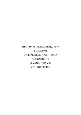
![a) Verilog coding:
module encoder(i, y);
input [7:0] i;
output [2:0] y;
assign y[2]= (i[4] + i[5] +i[6] + i[7]);
assign y[1]= (i[2] + i[3] +i[6] + i[7]);
assign y[0]= (i[1] + i[3] +i[5] + i[7]);
endmodule
b) Test bench
module encoder_tb();
reg [7:0]i1;
wire [2:0]y1;
encoder d1(i1, y1);
initial
begin
i1=8'b10000000;
i1=8'b01000000;
i1=8'b00100000;
i1=8'b00010000;
i1=8'b00001000;
i1=8'b00000100;
i1=8'b00000010;
i1=8'b00000001;
end
endmodule
c) Output waveform:](https://image.slidesharecdn.com/taski-171130133006/85/Task-i-18-320.jpg)


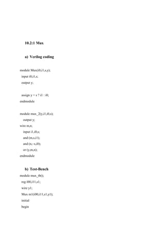
![8. Priority encoder:
a) Verilog coding:
module p_encoder(d,y);
input [3:0]d;
output [1:0]y;
assign y[1] = (d[3]+ (~d[2] * d[1]));
assign y[0] = (d[2] + d[3]);
endmodule
Verilog coding:
module Priority_enCode(Gate Level)r(d3,d2,d1,d0,y1,y0,y);
input d3,d2,d1,d0;
output y1,y0,y;
wire y1,y0,y,w1,w2;
not(w1,d2);
and(w2,w1,d1);
or(y0,w2,d3);
or(y1,d3,d2);
or(y,y1,d1,d0);
endmodule
a) Test bench
module p_encoder_tb();
reg [3:0]d1;
wire[1:0]y1;
p_encoder p1(d1,y1);](https://image.slidesharecdn.com/taski-171130133006/85/Task-i-21-320.jpg)


![a) Verilog coding:
module mux_top(a,b,c);
input [7:0]a;
input [2:0]b;
output c;
wire w1,w2;
mux d1(w1,a[0],a[1],a[2],a[3],b[1],b[0]);
mux d2(w2,a[4],a[5],a[6],a[7],b[1],b[0]);
Mux d3(w1,w2,b[2],c);
endmodule
b) Test-Bench:
module mux8_1_tb();
reg [7:0]a1;
reg [2:0]b1;
wire c1;
mux_top m1(a1,b1,c1);
initial
begin
a1[0]=0;
a1[1]=0;
b1[0]=0;
b1[1]=0;
b1[2]=0;
end
always #25 a1[0]=~a1[0];
always #50 a1[1]=~a1[1];
always #100 b1[0]=~b1[0];
always #200 b1[1]=~b1[1];](https://image.slidesharecdn.com/taski-171130133006/85/Task-i-27-320.jpg)
![always #400 b1[2]=~b1[2];
endmodule
c) Output waveform:
We can observe that the my output is follow input a[0] and a[1]
respectively.
12. Demux1_4
a) Verilog coding
module demux(I,S,Y);
input [1:0]S;
input I;
output [3:0]Y;
assign Y[0]= (~S[1] & ~S[0] & I);
assign Y[1]= (~S[1] & S[0] & I);
assign Y[2]= (S[1] & ~S[0] & I);
assign Y[3]= (S[1] & S[0] & I);](https://image.slidesharecdn.com/taski-171130133006/85/Task-i-28-320.jpg)
![endmodule
Verilog Code(Gate Level):
module demux_4(a,b,d,y0,y1,y2,y3);
output y0,y1,y2,y3;
input a,b,d;
wire w1,w2;
not(w1,a);
not(w2,b);
and(y0,w1,w2,d);
and(y1,w1,b,d);
and(y2,a,w2,d);
and(y3,a,b,d);
endmodule
b) Test bench
module demux_tb();
reg [1:0]S1;
reg I1;
wire [3:0]Y1;
demux D1(I1,S1,Y1);
initial
begin
I1=1;
S1[1]=0;
S1[0]=0;
end
always #100 S1[1]=~S1[1];
always #50 S1[0]=~S1[0];
endmodule
c) Output waveform](https://image.slidesharecdn.com/taski-171130133006/85/Task-i-29-320.jpg)


![Aim:
To design, simulate and implement code converters using schematic and
Verilog HDL.
Software Details:
For design Functional Simulation: Quartus II, ModelSim
For design Synthesis: Quartus II
For design Implementation: Quartus II
1. Binary to BCD
a) Verilog coding:
module B_TO_BCD(a,s);
input [3:0]a;
output[4:0]s;
assign s[4] = (a[1] & a[3]) | (a[3] & a[2]);
assign s[3] = (~a[1] & ~a[2] & a[3]);
assign s[2] = (a[2] & a[1]) | (a[2] & ~a[3]);
assign s[1] = (a[1] & ~a[3]) | (~a[1] & a[3] & a[2]);
assign s[0] = a[0];
endmodule
Task: 3 Design and Implementation of code converters using Verilog
HDL coding](https://image.slidesharecdn.com/taski-171130133006/85/Task-i-34-320.jpg)
![b) Test bench
module B_TO_BCD_TB();
reg [3:0]a1;
wire [4:0]s1;
B_TO_BCD m1(a1,s1);
initial
begin
#10 a1=4'b0000;
#10 a1=4'b0001;
#10 a1=4'b0010;
#10 a1=4'b0011;
#10 a1=4'b0100;
#10 a1=4'b0101;
#10 a1=4'b0110;
#10 a1=4'b0111;
#10 a1=4'b1000;
#10 a1=4'b1001;
#10 a1=4'b1010;
#10 a1=4'b1011;
#10 a1=4'b1100;
#10 a1=4'b1101;
#10 a1=4'b1110;
#10 a1=4'b1111;
#100 $stop;
end
endmodule](https://image.slidesharecdn.com/taski-171130133006/85/Task-i-35-320.jpg)
![c) Waveform:
2. BCD to Binary
a) Verilog code:
module BCD_TO_B(b,a);
input [4:0]b;
output[4:0]a;
assign a[4] = (b[3] & b[4]) | (b[1] & b[2] & b[4]);
assign a[3] = (b[3] & ~b[4]) | (~b[2] & ~b[3] & b[4]) | (~b[1] & ~b[3] & b[4]);
assign a[2] = (b[2] & ~b[4]) | (~b[1] & b[2]) | (b[1] & ~b[2] & b[4]);
assign a[1] = (b[1] ^ b[4]);
assign a[0] = b[0];
endmodule](https://image.slidesharecdn.com/taski-171130133006/85/Task-i-36-320.jpg)
![b) Test bench
module BCD_TO_B_TB();
reg [4:0]b1;
wire [4:0]a1;
BCD_TO_B m1(b1,a1);
initial
begin
#10 b1=5'b00000;
#10 b1=5'b00001;
#10 b1=5'b00010;
#10 b1=5'b00011;
#10 b1=5'b00100;
#10 b1=5'b00101;
#10 b1=5'b00110;
#10 b1=5'b00111;
#10 b1=5'b01000;
#10 b1=5'b01001;
#10 b1=5'b10000;
#10 b1=5'b10001;
#10 b1=5'b10010;
#10 b1=5'b10011;
#10 b1=5'b10100;
#10 b1=5'b10101;
#100 $stop;
end
endmodule](https://image.slidesharecdn.com/taski-171130133006/85/Task-i-37-320.jpg)
![c) Waveform:
3. Binary To Gray
a) Verilog code:
module B_TO_G(b,g);
output [3:0]g;
input [3:0]b;
xor x1(g[0],b[0],b[1]);
xor x2(g[1],b[1],b[2]);
xor x3(g[2],b[2],b[3]);
and a1(g[3],b[3],1'b1);
endmodule
b) Test bench:](https://image.slidesharecdn.com/taski-171130133006/85/Task-i-38-320.jpg)
![module B_TO_G_TB();
reg [3:0]b1;
wire [3:0]g1;
B_TO_G m1(b1,g1);
initial
begin
#10 b1=4'b0000;
#10 b1=4'b0001;
#10 b1=4'b0010;
#10 b1=4'b0011;
#10 b1=4'b0100;
#10 b1=4'b0101;
#10 b1=4'b0110;
#10 b1=4'b0111;
#10 b1=4'b1000;
#10 b1=4'b1001;
#10 b1=4'b1010;
#10 b1=4'b1011;
#10 b1=4'b1100;
#10 b1=4'b1101;
#10 b1=4'b1110;
#10 b1=4'b1111;
#100 $stop;
end
endmodule
c) Waveforms:](https://image.slidesharecdn.com/taski-171130133006/85/Task-i-39-320.jpg)
![4. Gray to Binary:
a) Verilog code:
module G_TO_B(g,b);
output [3:0]b;
input [3:0]g;
xor x1(b[0],b[1],g[0]);
xor x2(b[1],b[2],g[1]);
xor x3(b[2],b[3],g[2]);
and a1(b[3],g[3],1'b1);
endmodule
b) Test bench](https://image.slidesharecdn.com/taski-171130133006/85/Task-i-40-320.jpg)
![module G_TO_B_TB();
reg [3:0]g1;
wire [3:0]b1;
G_TO_B m1(g1,b1);
initial
begin
#10 g1=4'b0000;
#10 g1=4'b0001;
#10 g1=4'b0010;
#10 g1=4'b0011;
#10 g1=4'b0100;
#10 g1=4'b0101;
#10 g1=4'b0110;
#10 g1=4'b0111;
#10 g1=4'b1000;
#10 g1=4'b1001;
#10 g1=4'b1010;
#10 g1=4'b1011;
#10 g1=4'b1100;
#10 g1=4'b1101;
#10 g1=4'b1110;
#10 g1=4'b1111;
#100 $stop;
end
endmodule
c) Waveforms:](https://image.slidesharecdn.com/taski-171130133006/85/Task-i-41-320.jpg)
![5. Excess-3 To BCD
a) Verilog code:
module E_TO_BCD(e,b);
input [3:0]e;
output [3:0]b;
assign b[3] = (e[0] & e[1] & e[3]) | (e[2] & e[3]);
assign b[2] = (~e[0] & e[1] & e[3]) | (e[0] & e[1] & e[2]) | (~e[1] & ~e[2]);
assign b[1] = (e[1] ^ e[0]);
assign b[0] = ~e[0];
endmodule
b) Test-bench](https://image.slidesharecdn.com/taski-171130133006/85/Task-i-42-320.jpg)
![module E_TO_BCD_TB();
reg [3:0]e1;
wire [3:0]b1;
E_TO_BCD m1(e1,b1);
initial
begin
#10 e1=4'b0011;
#10 e1=4'b0100;
#10 e1=4'b0101;
#10 e1=4'b0110;
#10 e1=4'b0111;
#10 e1=4'b1000;
#10 e1=4'b1001;
#10 e1=4'b1010;
#10 e1=4'b1011;
#10 e1=4'b1100;
#100 $stop;
end
endmodule
c) Waveforms](https://image.slidesharecdn.com/taski-171130133006/85/Task-i-43-320.jpg)
![6. BCD To Excess-3
a) Verilog code:
module B_TO_E(b,e);
input [3:0]b;
output [3:0]e;
assign e[3]= b[3] | (b[2] & b[1]) | (b[2] & b[0]);
assign e[2]= (~b[2] & b[1]) | (~b[2] & b[0]) | (b[2] & ~b[1] & ~b[0]);
assign e[1]= (b[1] & b[0]) | (~b[1] & ~b[0]);
assign e[0]= ~b[0] ;
endmodule
b) Test-bench](https://image.slidesharecdn.com/taski-171130133006/85/Task-i-44-320.jpg)
![module B_TO_E_TB();
reg [3:0]b1;
wire [3:0]e1;
B_TO_E m1(b1,e1);
initial
begin
#10 b1=4'b0000;
#10 b1=4'b0001;
#10 b1=4'b0010;
#10 b1=4'b0011;
#10 b1=4'b0100;
#10 b1=4'b0101;
#10 b1=4'b0110;
#10 b1=4'b0111;
#10 b1=4'b1000;
#10 b1=4'b1001;
#100 $stop;
end
endmodule](https://image.slidesharecdn.com/taski-171130133006/85/Task-i-45-320.jpg)

![Aim:
To design, simulate and implement Ripple carry adder using schematic and
Verilog HDL.
Software Details:
For design Functional Simulation: Quartus II, ModelSim
For design Synthesis: Quartus II
For design Implementation: Quartus II
a) RC_Verilog Code:
module RC_adder(a2,b2,cin2,s2,cout2);
input [3:0]a2,b2;
wire c1,c2,c3;
input cin2;
output [3:0]s2;
output cout2;
FA f1(a2[0],b2[0],cin2,s2[0],c1);
FA f2(a2[1],b2[1],c1,s2[1],c2);
FA f3(a2[2],b2[2],c2,s2[2],c3);
FA f4(a2[3],b2[3],c3,s2[3],cout2);
Endmodule
b) FA_Verilog code:
Task: 4 Design and Implementation of Combinational Circuits using
Verilog HDL coding](https://image.slidesharecdn.com/taski-171130133006/85/Task-i-47-320.jpg)
![module FA(a,b,cin,s,cout);
input a,b,cin;
output s,cout;
wire s,cout;
wire w1,w2,w3,w4;
xor x1(w1,a,b);
xor x2(s,w1,cin);
and a1(w2,a,b);
and a2(w3,cin,b);
and a3(w4,a,cin);
or o1(cout,w2,w3,w4);
endmodule
c) Test bench:
module RC_FA_TB();
reg [3:0]a2,b2;
reg cin2;
wire [3:0]s2;
wire cout2;
RC_adder f11(a2,b2,cin2,s2,cout2);
initial
begin
cin2=0;
#10 a2=4'b1100; b2=4'b0001;
#10 a2=4'b1100; b2=4'b1001;
#10 $stop;
end
endmodule
d) Waveforms:](https://image.slidesharecdn.com/taski-171130133006/85/Task-i-48-320.jpg)


The document outlines an assignment focused on designing, simulating, and implementing basic combinational circuits using Verilog HDL. It includes examples of various digital logic gates, adders, subtractors, multiplexers, decoders, and encoders with accompanying Verilog code and test benches. The aim is to provide practical experience with digital design tools including Quartus II and ModelSim.