Download to read offline


![36
REFERENCES:
[1] Hokanson, D.Eugene; Sumner, David S.; Strandness, D.Eugene, "An Electrically
Calibrated Plethysmograph for Direct Measurement of Limb Blood Flow," in Biomedical
Engineering, IEEE Transactions on , vol.BME-22, no.1, pp.25-29, Jan. 1975
[2] Deepak Verma, "Real Time Optical Heart Monitor", (IJCSIT) International Journal of
Computer Science and Information Technologies, Vol. 5 (6) , 2014
[3] The Microcontrollers, Architecture, Programming and Applications-K Uma Rao,
Andhe Pallavi, Pearson 2009
[4] Op-Amps & Linear ICs – Ramakanth A. Gayakwad, PHI, 2003.
[5] www.allaboutcircuits.com
[6] www.microchip.com](https://image.slidesharecdn.com/0ce37f4e-2fb0-430a-926f-725a94db8122-161210175049/85/FINAL-DOC-42-320.jpg)


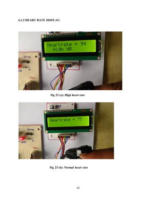
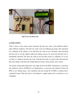
This project involves designing a real-time heart beat monitoring system using a PIC16F876 microcontroller. The system measures a subject's heart rate using an infrared sensor attached to the finger. It averages the measured heart rate and displays it on an LCD screen. The system is powered by a regulated 5V power supply. It uses a bridge rectifier and voltage regulator to provide stable power from a 230/12V step-down transformer. The microcontroller processes the heart rate signal from the sensor and sends the information to the LCD for display. An LED or buzzer can also be used for visual or audio indication of the measured heartbeat.