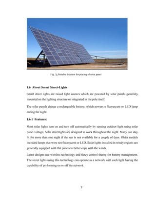
The document describes a solar powered smart street light system project. It includes the construction of a prototype solar tracking system to maximize solar energy collection and conversion. The solar energy is then stored in batteries and used to power an automatic street light control system. The street lights are automatically turned on and off in response to detected vehicle movement to conserve energy. The overall goal is to develop a system using solar energy to automatically control street lights as needed.

![viii
LITERATURE REVIEW
In this firstly the microcontroller is major part of solar tracking system, it controls all operation.
The solar panel is aligned according to algorithm under the control of microcontroller [1]. Two
dc gear motors are used for the movement of solar panel in two
Axes [2]. The speed of dc gear motor is controlled by motor driver circuit. PWM or Pulse
Width
Modulation technique is used to digitally control speed of dc motors. The LDRs are connected
in each side of solar panel which compare intensity of light and give signal accordingly to
Arduino for movement of solar panel[3].
The energy which we obtain from solar panel is stored in the battery bank. Now this power is
used as an input power source for the street light[4]. In street light system, LDR is connected
which automatically turn on street light at night and turn off at day. The IR sensor is placed on
highway as it detects the vehicle movement, it turns on the street light of that particular area
where vehicle is detected by IR sensor & remaining light remains off[5]. So, this whole system
helps to save more energy, which leads to increase in efficiency of the system.](https://image.slidesharecdn.com/reportdepartment-200504102629/85/Report-on-solar-based-street-light-system-9-320.jpg)

![1
CHAPTER 1: INTRODUCTION
1.1 About Solar tracking system
A solar tracker is a device that orients a payload toward the Sun. Payloads are usually solar
panels, parabolic troughs, Fresnel reflectors, lenses or the mirrors of a heliostat.
For flat-panel photovoltaic systems, trackers are used to minimize the angle of incidence
between the incoming sunlight and a photovoltaic panel. This increases the amount of
energy produced from a fixed amount of installed power generating capacity. In standard
photovoltaic applications, it was predicted in 2008-2009 that trackers could be used in at
least 85% of commercial installations greater than one megawatt from 2009 to 2012.
However, as of April 2014, there is not any data to support these predictions.
In concentrator photovoltaics (CPV) and concentrated solar power (CSP) applications,
trackers are used to enable the optical components in the CPV and CSP systems. The optics
in concentrated solar applications accept the direct component of sunlight light and
therefore must be oriented appropriately to collect energy. Tracking systems are found in
all concentrator applications because such systems collect the sun's energy with maximum
efficiency when the optical axis is aligned with incident solar radiation[1].
Sunlight has two components, the "direct beam" that carries about 90% of the solar energy,
and the "diffuse sunlight" that carries the remainder – the diffuse portion is the blue sky on
a clear day, and is a larger proportion of the total on cloudy days. As the majority of the
energy is in the direct beam, maximizing collection requires the Sun to be visible to the
panels for as long as possible. However, please note that in more cloudy areas the ratio of
direct vs. diffuse light can be as low as 60%:40% or even lower.
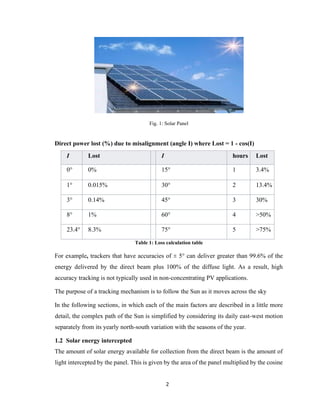
The energy contributed by the direct beam drops off with the cosine of the angle between
the incoming light and the panel. In addition, the reflectance (averaged across all
polarizations) is approximately constant for angles of incidence up to around 50°, beyond
which reflectance degrades rapidly.](https://image.slidesharecdn.com/reportdepartment-200504102629/85/Report-on-solar-based-street-light-system-11-320.jpg)


![8
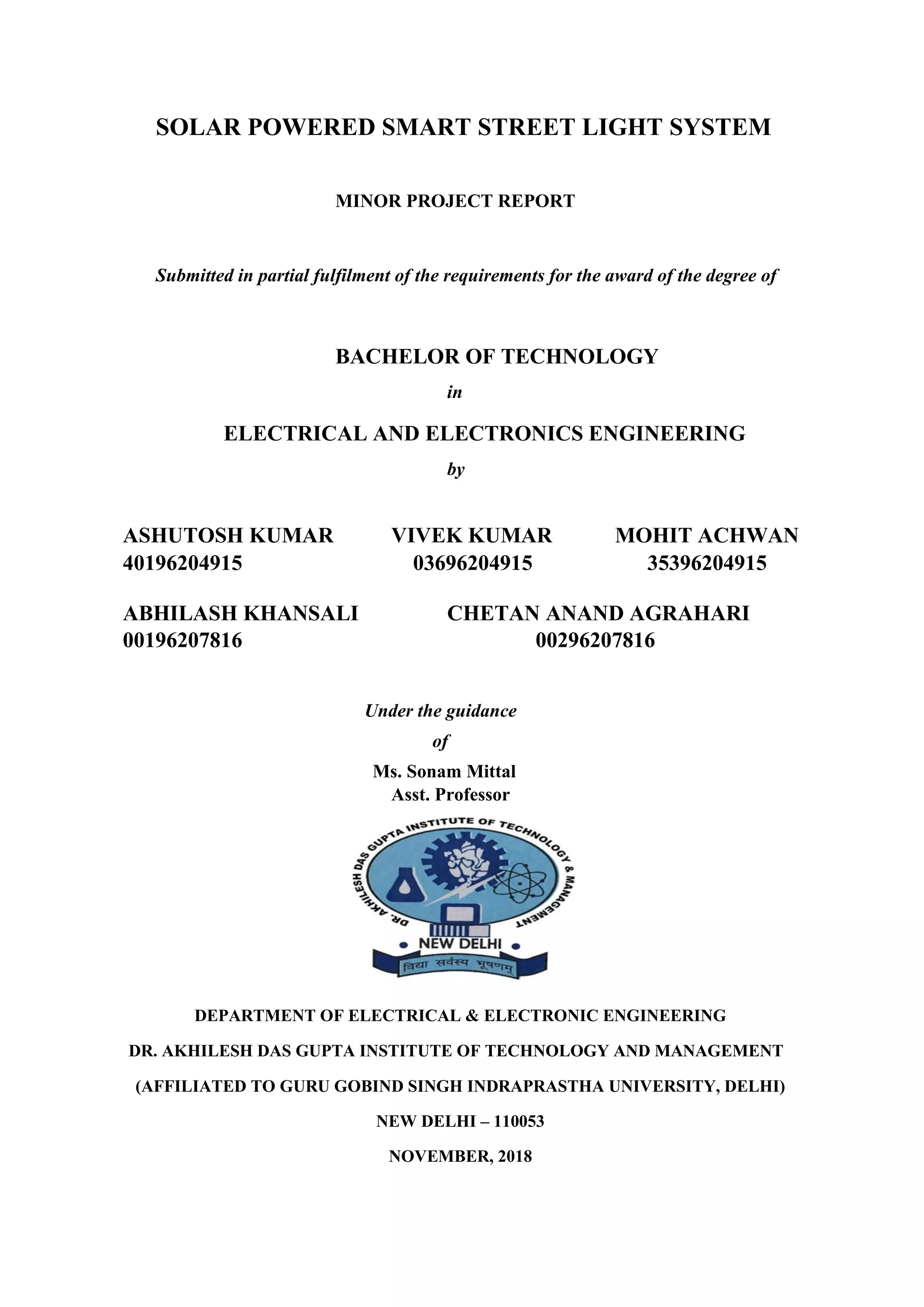
CHAPTER 2: COMPONENTS
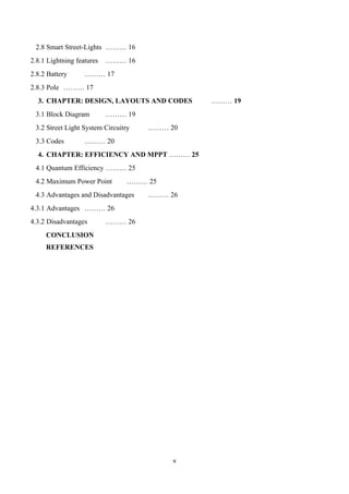
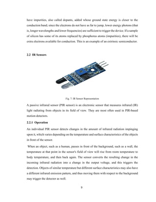
2.1 Light Dependent Resistor
Fig.6: LDR representation and LDR sensor
A Light Dependent Resistor (LDR) or a photo resistor is a device whose resistivity is a
function of the incident electromagnetic radiation. Hence, they are light sensitive devices.
They are also called as photo conductors, photo conductive cells or simply photocells. They
are made up of semiconductor materials having high resistance. There are many different
symbols used to indicate an LDR, one of the most commonly used symbols is shown in the
figure below. The arrow indicates light falling on it.
A photoresistor is made of a high resistance semiconductor. In the dark, a photoresistor can
have a resistance as high as several megohms (MΩ), while in the light, a photoresistor can
have a resistance as low as a few hundred ohms. If incident light on a photoresistor exceeds
a certain frequency, photons absorbed by the semiconductor give bound electrons enough
energy to jump into the conduction band. The resulting free electrons (and their hole
partners) conduct electricity, thereby lowering resistance. The resistance range and
sensitivity of a photoresistor can substantially differ among dissimilar devices. Moreover,
unique photoresistors may react substantially differently to photons within certain
wavelength bands [2].
A photoelectric device can be either intrinsic or extrinsic. An intrinsic semiconductor has
its own charge carriers and is not an efficient semiconductor, for example, silicon. In
intrinsic devices the only available electrons are in the valence band, and hence the photon
must have enough energy to excite the electron across the entire bandgap. Extrinsic devices](https://image.slidesharecdn.com/reportdepartment-200504102629/85/Report-on-solar-based-street-light-system-18-320.jpg)
![13
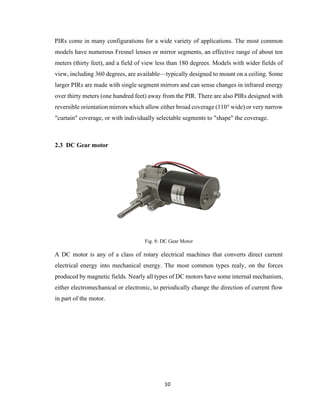
Fig. 11: Photovoltaic cell solar panel
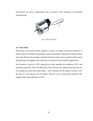
A single solar module can produce only a limited amount of power; most installations
contain multiple modules. A photovoltaic system typically includes an array of photovoltaic
modules, an inverter, a battery pack for storage, interconnection wiring, and optionally a
solar tracking mechanism.
The efficiency of the solar cells used in a photovoltaic system, in combination with latitude
and climate, determines the annual energy output of the system. For example, a solar panel
with 20% efficiency and an area of 1 m2
will produce 200 W at Standard Test Conditions,
but it can produce more when the sun is high in the sky and will produce less in cloudy
conditions or when the sun is low in the sky. In central Colorado, which receives annual
insolation of 5.5 kWh/m2
/day (or 230W/m2
),[1]
such a panel can be expected to produce 400
kWh of energy per year. However, in Michigan, which receives only 3.8 kWh/m2
/day,
annual energy yield will drop to 280 kWh for the same panel. At more northerly European
latitudes, yields are significantly lower: 175 kWh annual energy yield in southern England.
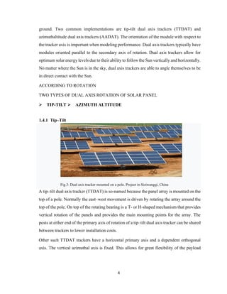
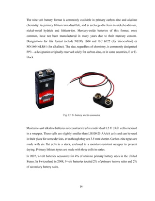
2.6 Battery
The nine-volt battery, or 9-volt battery, is a common size of battery that was introduced for
the early transistor radios. It has a rectangular prism shape with rounded edges and a
polarized snap connector at the top. This type is commonly used in walkie-talkies, clocks
and smoke detectors.](https://image.slidesharecdn.com/reportdepartment-200504102629/85/Report-on-solar-based-street-light-system-23-320.jpg)
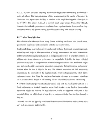
![15
Type IEC
name
ANSI/NEDA
name
Typical
capacity
in mAh
Nominal
voltages
Primary
(disposable)
Alkaline 6LR61 1604A 550 9
6LP3146 1604A 550 9
Zinc–
carbon
6F22 1604D 400 9
Lithium 1604LC 1200 9
Rechargeable Ni-Cd 6KR61 11604 120 7.2, 8.4
NiMH 6HR61 7.2H5 175-300 7.2, 8.4,
9.6
Lithium
polymer
520 7.4
Lithiumion 620 7.4
Table 2: Different types of batteries
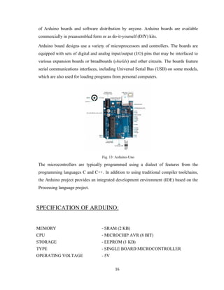
2.7 Arduino
Arduino is an open-source hardware and software company, project and user community
that designs and manufactures single-board microcontrollers and microcontroller kits for
building digital devices and interactive objects that can sense and control objects in the
physical and digital world. Its products are licensed under the GNU Lesser General Public
License (LGPL) or the GNU General Public License (GPL),[1]
permitting the manufacture](https://image.slidesharecdn.com/reportdepartment-200504102629/85/Report-on-solar-based-street-light-system-25-320.jpg)
![18
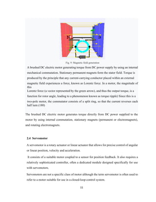
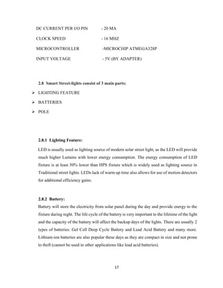
2.8.3 Pole:
Strong Poles are necessary to all street lights, especially to solar street lights as there are
often components mounted on the top of the pole: fixtures, panels and sometimes batteries.
However, in some newer designs, the PV panels and all electronics are integrated in the
pole itself. Wind resistance is also a factor.
Also, there are some accessories, like foundation cage and battery box.
Fig. 14: Solar street light at bus stop
Each street light can have its own photo voltaic panel, independent of other street lights.
Alternately, a number of panels can be installed as a central power source on a separate
location and supply power to a number of street lights.
All In One type Solar street lights are also gaining popularity. In this type the Solar panel,
Lithium-ion battery and LED light are fitted together in a compact way. This enhances
battery protection against theft and also the entire unit is weather proof.
City of Las Vegas was the first city in the world that tested new EnGoPlanet Solar
Street lights that are coupled with kinetic tiles that produce electricity when people walk
over them.
The charge and discharge cycles of the battery is also very important considering the overall
cost of the project[3].](https://image.slidesharecdn.com/reportdepartment-200504102629/85/Report-on-solar-based-street-light-system-28-320.jpg)
![19
CHAPTER 3: DESIGN, LAYOUT AND CODES
3.1 Block Diagram
Fig 15: Block Diagram of System
The 4 LDRs (2 for horizontal detection and 2 for vertical detection) detects the intensity of
the light from the Sun and sends a signal to Arduino Uno, and then the Arduino Uno will
send signal proportional from the respective LDR/LDRs to the motors through the motor
driver module for their rotation according to the need. The motor then, drives or rotates the
solar panel either vertically or horizontally [4], accordingly. Solar Panel will then charge
the battery in the battery bank through which the electrical energy will store into the
batteries in the chemical form for the usage of that energy for later times at night for Street
sLight to glow and provide the necessary illumination for the moving vehicles.](https://image.slidesharecdn.com/reportdepartment-200504102629/85/Report-on-solar-based-street-light-system-29-320.jpg)
![20
3.2 Street Light System Circuitry
Fig. 16: Block Diagram of Smart Street-Light System
An LDR sensor is connected to the IR module which will sense the presence of the sunlight
and accordingly change its resistance value and will either activate the IR module or
deactivate it according to the condition. After the condition is checked, the IR sensor set
will send and receive the signal and will detect whether there is any vehicle that is in the
road or not and, will send this signal to the IR module for further instruction to the LEDs
on the Street Lights. If they detect any vehicle on the road then the LEDs will glow and if
they didn’t sense anything then the LEDs will remain off [5].
3.3 Codes
#define LightValue 700
#define m21 8
#define m22 9
#define m11 10
#define m12 11
#define ldr1 A0](https://image.slidesharecdn.com/reportdepartment-200504102629/85/Report-on-solar-based-street-light-system-30-320.jpg)
![24
CHAPTER 4: EFFICIENCY AND MPPT
4.1 Quantum Efficiency
Quantum efficiency refers to the percentage of photons that are converted to electric current
(i.e., collected carriers) when the cell is operated under short circuit conditions. The
"external" quantum efficiency of a silicon solar cell includes the effect of optical losses such
as transmission and reflection.
In particular, some measures can be taken to reduce these losses. The reflection losses,
which can account for up to 10% of the total incident energy, can be dramatically decreased
using a technique called texturization, a light trapping method that modifies the average
light path.
Quantum efficiency is most usefully expressed as a spectral measurement (that is, as a
function of photon wavelength or energy). Since some wavelengths are absorbed more
effectively than others, spectral measurements of quantum efficiency can yield valuable
information about the quality of the semiconductor bulk and surfaces. Quantum efficiency
alone is not the same as overall energy conversion efficiency, as it does not convey
information about the fraction of power that is converted by the solar cell [6].
4.2 Maximum Power Point
A solar cell may operate over a wide range of voltages (V) and currents (I). By increasing
the resistive load on an irradiated cell continuously from zero (a short circuit) to a very high
value (an open circuit) one can determine the maximum power point, the point that
maximizes V×I; that is, the load for which the cell can deliver maximum electrical power
at that level of irradiation. (The output power is zero in both the short circuit and open circuit
extremes).
A high quality, monocrystalline silicon solar cell, at 25 °C cell temperature, may produce
0.60 V open-circuit (VOC). The cell temperature in full sunlight, even with 25 °C air
temperature, will probably be close to 45 °C, reducing the open-circuit voltage to 0.55 V
per cell. The voltage drops modestly, with this type of cell, until the short-circuit current is](https://image.slidesharecdn.com/reportdepartment-200504102629/85/Report-on-solar-based-street-light-system-34-320.jpg)
![25
approached (ISC). Maximum power (with 45 °C cell temperature) is typically produced with
75% to 80% of the open-circuit voltage (0.43 V in this case) and 90% of the short-circuit
current. This output can be up to 70% of the VOC x ISC product. The short-circuit current
(ISC) from a cell is nearly proportional to the illumination, while the open-circuit voltage
(VOC) may drop only 10% with an 80% drop in illumination. Lower-quality cells have a
more rapid drop in voltage with increasing current and could produce only 1/2 VOC at 1/2
ISC. The usable power output could thus drop from 70% of the VOC x ISC product to 50% or
even as little as 25%. Vendors who rate their solar cell "power" only as VOC x ISC, without
giving load curves, can be seriously distorting their actual performance.
The maximum power point of a photovoltaic varies with incident illumination.
For example, accumulation of dust on photovoltaic panels reduces the maximum power
point.
For systems large enough to justify the extra expense, a maximum power point tracker tracks the
instantaneous power by continually measuring the voltage and current (and hence, power
transfer), and uses this information to dynamically adjust the load so the maximum power is always
transferred, regardless of the variation in lighting [7].
Fig.17 MPPT graph according to intensity of sun](https://image.slidesharecdn.com/reportdepartment-200504102629/85/Report-on-solar-based-street-light-system-35-320.jpg)
![REFERENCE
[1] Tar lochan Kaur, Suraiya Mahajan, Shilpa Verma, Priyanka, Jamila Gambhir, “Arduino
Based Low Cost Dual Axis Solar Tracker”, IEEE International conference on Power
Electronics, Intelligent control and Energy Systems, pp. 1-5, 2016.
[2] W. Xiao, N. Ozog, and W. G. Dunford, “Topology study of photovoltaic interface for
maximum power point tracking,” IEEE Trans. Ind. Electron., vol. 54, no. 3, pp. 1696–1704,
Jun. 2007.
[3] J. H. R. Enslin, M. S. Wolf, D. B. Snyman, and W. Swingers, “Integrated photovoltaic
maximum power point tracking converter,” IEEE Trans. Ind. Electron., vol. 44, no. 6, pp.
769– 773, Dec. 1997.
[4] R. J. Wai, W. H. Wang, and C. Y. Lin, “High-performance stand-alone photovoltaic
generation system,” IEEE Trans. Ind. Electron., vol. 55, no. 1, pp. 240–250, Jan. 2008.
[5] Megha J. K1, Pallavi K.S2, Ramya N. B3, Varsha G.N4, Shruti B.M5 ''Arduino based
dual axis solar tracking system' 'International Research Journal of Engineering and
Technology (IRJET) e-ISSN: 2395-0056 Volume: 05 Issue:05 ,May-2018.](https://image.slidesharecdn.com/reportdepartment-200504102629/85/Report-on-solar-based-street-light-system-38-320.jpg)