Download to read offline


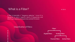

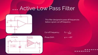
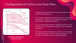


The document provides an overview of active filters, which are analog circuits that utilize active components like amplifiers to implement frequency selective filtering. It classifies active filters into four types: low pass, high pass, band pass, and band stop, detailing their functions, configurations, and frequency responses. The document also discusses the merits and demerits of active filters, including their flexibility and performance benefits, while highlighting their limitations in cost, power handling, and frequency range.