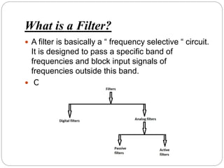
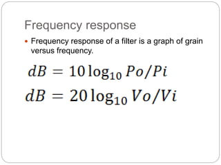
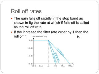
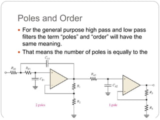
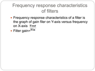
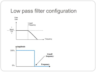
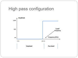
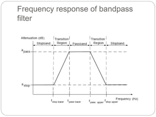
Gandhinagar institute of
technology
 Sub – Analog Electronics(2130902)
 Topic – Active Filter
 Guided by – Prof. Pratik Gohel
 Sem – 3rd
 Branch – Electrical (b3)
 Academic year – 2015&2016
Prepared by
 Sodha Manthansinh (140120109057)
Active Filter
What is a Filter?
 A filter is basically a “ frequency selective “ circuit.
It is designed to pass a specific band of
frequencies and block input signals of
frequencies outside this band.
 Classification of Filters
What is Active Filter?
 The active filters use active devices such as an op-amp
or transistors alongwith the passive components.
 Active filters have more sharp frequency response
characteristics and have many other advantages over
passive filters.
 Types of active filter:
 Low pass filter
 High pass filter
 Bandpass filter
 Bandstop filter
Merits of active filter
 Low cost
 Flexibility in gain
 No loading problem
 No insertion
 Passband gain
 Small component size
 Use of the inductors can be avoided
 Control impedence
Demerits
 Its has need dc supply.
 Active filter are limited in their frequency range
.op-amp had a finite gain bandwidth product.
 Active filters can not handle of large amount of
power.
Frequency response
 Frequency response of a filter is a graph of grain
versus frequency.
Angular Velocity
 Sometimes the frequency is expressed as
angular velocity in radians/second.
 The relation between angular frequency and f is
as following
Characteristics of terminology
 The frequency response graphs discussed the
previous slide
 A low pass filter passes all the frequencies below
its cut-off frequency and stop all the frequencies
which are above the critical frequency.
 The critical frequency forms the boundary
between the two bands called as pass band and
stop band of the filter.
 Frequency response of an ideal low pass filter
 Pass band
it is the band or range of frequency which are
allowed to pass out through the output by
filters without any attenuation.
 Stop band
it is the band or range of frequencies which are
not allowed to pass through to the output by the
filter.
Roll off rates
 The gain falls off rapidly in the stop band as
shown in fig the rate at which if falls off is called
as the roll off rate .
 If the increase the filter rate order by 1 then the
roll off rate is increased by 20 dBdecade.
Poles and Order
 For the general purpose high pass and low pass
filters the term “poles” and “order” will have the
same meaning.
 That means the number of poles is equally to the
order of filters this also tell the roll of filters .
Frequency response characteristics
of filters
 Frequency response characteristics of a filter is
the graph of gain filer on Y-axis versus frequency
on X-axis
 Filter gain=
Low pass filter configuration
 it shows that a low pass filter has a constant gain
from 0 to a high cut off frequency fc.
 The frequencies between 0 to fc are known as “
passband frequencies” whereas the frequencies
beyond fc are known as the “stopband
frequencies”.
 At f= fc the filter gain makes a sudden transition
to zero. Therefore all the frequencies beyond fc
are completely attenuated.
 Previous slide figure shows the frequency
response of a practical low-pass filter. gain does
not change suddenly at f= fc. Instead as f
increase, the gain reduces gradually.
High pass configuration
 Its “stopband” extends from f=0 to f=fc where fc
is the cut off frequency. the “passband” will be for
all frequencies above Fc.
 The gain of an ideal high-pass filter is 0 over its
stopband constant over its passband.
 The gain make a sudden transition from 0 to 1 at
f= fc show in figure.
Frequency response of bandpass
filter
 Its “passband” extends between the two cut-off
frequencies fL anfd fH with fH>fL. The
frequencies outside this passband lie in the
“stopband “.
 Thae gain of an ideal bandpass filter is 0 over the
stopband and constant over its passband.
 The gain will make sudden trasitions from 0 to 1
at f=fL and from 1 to 0 f=fJ as shown in figure.
Bandstop filter
 A bandstpo or bandreject filter is complementary
to the bandpass filter it blocks out the frequency
components within the stopband as shown in
figure.
Active filter

Active filter

  • 1.
    Gandhinagar institute of technology Sub – Analog Electronics(2130902)  Topic – Active Filter  Guided by – Prof. Pratik Gohel  Sem – 3rd  Branch – Electrical (b3)  Academic year – 2015&2016
  • 2.
    Prepared by  SodhaManthansinh (140120109057)
  • 3.
  • 4.
    What is aFilter?  A filter is basically a “ frequency selective “ circuit. It is designed to pass a specific band of frequencies and block input signals of frequencies outside this band.  Classification of Filters
  • 5.
    What is ActiveFilter?  The active filters use active devices such as an op-amp or transistors alongwith the passive components.  Active filters have more sharp frequency response characteristics and have many other advantages over passive filters.  Types of active filter:  Low pass filter  High pass filter  Bandpass filter  Bandstop filter
  • 6.
    Merits of activefilter  Low cost  Flexibility in gain  No loading problem  No insertion  Passband gain  Small component size  Use of the inductors can be avoided  Control impedence
  • 7.
    Demerits  Its hasneed dc supply.  Active filter are limited in their frequency range .op-amp had a finite gain bandwidth product.  Active filters can not handle of large amount of power.
  • 8.
    Frequency response  Frequencyresponse of a filter is a graph of grain versus frequency.
  • 10.
    Angular Velocity  Sometimesthe frequency is expressed as angular velocity in radians/second.  The relation between angular frequency and f is as following
  • 11.
    Characteristics of terminology The frequency response graphs discussed the previous slide  A low pass filter passes all the frequencies below its cut-off frequency and stop all the frequencies which are above the critical frequency.  The critical frequency forms the boundary between the two bands called as pass band and stop band of the filter.  Frequency response of an ideal low pass filter
  • 12.
     Pass band itis the band or range of frequency which are allowed to pass out through the output by filters without any attenuation.  Stop band it is the band or range of frequencies which are not allowed to pass through to the output by the filter.
  • 13.
    Roll off rates The gain falls off rapidly in the stop band as shown in fig the rate at which if falls off is called as the roll off rate .  If the increase the filter rate order by 1 then the roll off rate is increased by 20 dBdecade.
  • 14.
    Poles and Order For the general purpose high pass and low pass filters the term “poles” and “order” will have the same meaning.  That means the number of poles is equally to the order of filters this also tell the roll of filters .
  • 15.
    Frequency response characteristics offilters  Frequency response characteristics of a filter is the graph of gain filer on Y-axis versus frequency on X-axis  Filter gain=
  • 16.
    Low pass filterconfiguration
  • 17.
     it showsthat a low pass filter has a constant gain from 0 to a high cut off frequency fc.  The frequencies between 0 to fc are known as “ passband frequencies” whereas the frequencies beyond fc are known as the “stopband frequencies”.  At f= fc the filter gain makes a sudden transition to zero. Therefore all the frequencies beyond fc are completely attenuated.  Previous slide figure shows the frequency response of a practical low-pass filter. gain does not change suddenly at f= fc. Instead as f increase, the gain reduces gradually.
  • 18.
  • 19.
     Its “stopband”extends from f=0 to f=fc where fc is the cut off frequency. the “passband” will be for all frequencies above Fc.  The gain of an ideal high-pass filter is 0 over its stopband constant over its passband.  The gain make a sudden transition from 0 to 1 at f= fc show in figure.
  • 20.
    Frequency response ofbandpass filter
  • 21.
     Its “passband”extends between the two cut-off frequencies fL anfd fH with fH>fL. The frequencies outside this passband lie in the “stopband “.  Thae gain of an ideal bandpass filter is 0 over the stopband and constant over its passband.  The gain will make sudden trasitions from 0 to 1 at f=fL and from 1 to 0 f=fJ as shown in figure.
  • 22.
    Bandstop filter  Abandstpo or bandreject filter is complementary to the bandpass filter it blocks out the frequency components within the stopband as shown in figure.